Description of the electrical circuit of the radial drilling machine 2E52
Voltage is supplied to the power circuit and to the control circuit when the circuit breaker lever A is turned on (Fig. 10).
At the same time, the control and lighting transformer TU0 is turned on. The engine control switch is in the neutral position, i.e. all contacts KPS, KPV, KPN are open.
The traverse is clamped and located at the middle height of the column. In this position, the NC contacts of the PVV and PVN limit switches are closed.
When you turn the control handle 4 (see Fig. 3) along groove I upward, the KPS contact (2-11) closes, and the transition contact KPV (2-1) turns on and off. At this time, the KB coil of the reversing starter is turned on, the NO block contact KB (2-1) switches to self-power and the main NO contacts KB turns on the electric motor.
The engine is turned off by moving the handle to the neutral position.
Reversing the engine is done by turning the handle down. In this case, the contact of the KPN switch is closed and the coil of the KN starter is turned on.
Rapid movement of the traverse is carried out by turning the control handle along groove II with the sleeve in the relaxed position on the column.
The movement of the traverse up and down is limited by the PVV and PVN limit switches, which, when the NC contacts in the circuit of the starter coils are opened, turn off the engine.
The local lighting lamp is turned on by the VO switch.
see also
- Lamps for local lighting of machine tools
- Automated milling machine
- Four-sided wood lathe
- VVG cable production machine
Mechanical processing of metal on machines and lines- DIY turbine balancing machine
- Red proletarian lathe
- Electric motor rewinding machine
Wiring diagram of lathe 1a616- Cable Length Measuring Machine
- Woodworking lathes
Arrangement of components of the radial drilling machine 2N55
Specification of components of the drilling machine 2N55
- Slab, plinth, column – 11 (node number)
- Cooling – 12
- Sleeve and clip – 21
- Drill head lifting mechanism – 31
- Hydraulic clamping mechanism – 32
Specification of components of the drilling head SG-50N, SG-350N
- Friction clutch – 15
- Gearbox – 16
- Feed box – 17
- Worm shaft – 25
- Feed switching mechanism – 26
- Drill head clamp – 36
- Counterweight – 37
- Hydropreselector – 45
- Hydraulic preselector drive – 46
- Hydraulic equipment – 47
- Friction clutch control – 48
- Controlling a set of speeds and feeds – 49
- Spindle –
- Electrical equipment – 93
- Electric remote control – 95
- Electrical cabinet – 96
- Introductory panel – 97
General layout of the 2n55 machine
The base of the machine is a foundation plate on which the plinth is fixedly fixed. A rotating column made of steel pipe is mounted in the base on bearings. The machine arm with the drilling head is placed on the column and moves along it using a lifting mechanism mounted in the housing at the upper end of the column. The same housing contains a hydromechanical device for clamping the column and a current supply device for powering the rotating and moving parts of the machine. The lifting mechanism is connected to the sleeve by a lead screw.
The drilling head is made in the form of a separate power unit and contains components: speed and feed boxes, feed mechanism, spindle with counterweight, etc. It moves manually along the sleeve guides. In the desired position, the head is fixed by a clamping mechanism installed on it.
The base plate contains a tank and a pumping unit for supplying coolant to the tool. A table is installed on the stove for processing small-sized parts.
All machine controls are concentrated on the drilling head. On the plinth panel there are buttons for the input switch that connects the machine to an external power supply, and buttons for controlling the cooling pump. To illuminate the working area, a fluorescent lamp is installed in the lower part of the drilling head, behind the spindle.
The electrical equipment is mounted in a niche located on the reverse side of the sleeve.
Drive unit
The main mechanism for ensuring rotation speed, its switching during drilling and the operation of the gearbox is characterized by one feature. Having disassembled the gearbox of the 2K52 drilling machine, the passport of which includes its own electric drive, we can say that there are several similar mechanisms.
It is allowed to install 3 electric motors in accordance with the operating manual 2K52 and other regulatory documents. The power of the main drive is 1.5 kW.
The manual indicates the weight of the installation - 1250 kg, and also displays a full explanation of the name of the machine.
The kinematic scheme is based on four chains, the first of which is the rotation chain of the main spindle. When disassembling the installation, you can notice that the load when the spindle rotates is evenly distributed over the gearbox and U-type drive shaft.
Kinematic diagram of the 2K52 machine
The components of the kinetic scheme are also:
- Feed chain.
- Chain of vertical displacement of the main sleeve.
- Column clamping circuit.
During the assembly process, the designers equipped the 2K52 installation with the maximum set of additional modules. Expanded functionality allows you to increase the accuracy of all operations, it also becomes possible to work with complex workpieces, and productivity is accelerated.
As a result, the 2K52 drilling machine has parameters suitable for performing many jobs, the adjustment of which allows one to achieve fairly high accuracy. Each work operation is carried out without complex manipulations, which can be performed even by a worker with minimal qualifications. The resulting holes always have the correct shape.
Cooling system
As previously noted, the design of the radial drilling machine has a cooling system. The features of this system include the following points:
- The machine model is equipped with a container and a hole for filling coolant.
- Liquid can be supplied to the main part of the head. The passport included information that specifies the installation of an electric pump to create pressure in the system.
- There are channels in the plate through which part of the liquid returns back to the reservoir.
Electrical circuit of the machine 2l53u
The electrical circuit consists of several automatic switches, electric motor control buttons, an electric pump and several motors and fuses. The electrical panel contains several control keys, as well as a plate with basic information about the radial drilling machine.
Model 2l53u is installed without fastening to the base. The weight of the 2l53u radial drilling machine is 2,100 kg, which determines its reliable installation. Its price can vary over a fairly wide range. The decoding of the name of the machine has an index indicating the reduced weight of the model.
Drill head
During the manufacture of the body, cast iron was used, which is resistant to vibration loads and is not exposed to high humidity. In the middle there is a system for switching spindle rotation speeds or feed rates
To significantly increase the service life of the structure, the contacting parts are lubricated with a specialized suspension. To do this, install a lubrication pump, main motion drive or spindle brake on the housing.
The gearbox is controlled through handles installed on the outside. During the manufacture of gears, alloy steel is used, which has very high wear resistance.
Barrel and plate for basing the workpiece
The reduced radial drilling machine 2l53u has the following main elements:
- Plate for basing the workpiece and sleeve. The passport contains the following information about these structural elements: during the manufacture of the slab, cast iron is made, and T-shaped grooves are located on the surface. The design also has a vertical column with a sleeve on top. The sleeve has guides along which the drilling head moves. Stops serve as a limiter. In addition, the barrel moves along the column using a screw. Technical characteristics determine high wear resistance due to the installation of a fluid reservoir, as well as a pump to create the required pressure. The lubricant supply can be controlled through an installed electrical cabinet at the end.
- Barrel. The operating instructions determine the possibility of positioning the spindle at different heights relative to the plate. The body is made of cast iron by casting. The structure is clamped manually using a handle. There is also a contact blocking switch, which eliminates the possibility of accidental movement of the barrel.
Barrel of machine 2L53U
Machine plate 2L53U
When reviewing this model, we note that the drilling head can extend beyond the slab. The main electric motor is installed on top of the stand and is located vertically.
Specifications
- Drilling diameter in steel 45 according to GOST 1050-38, mm 32
- Drilling diameter in cast iron SCH according to GOST 1412-89, mm 40
- Distance from the spindle axis to the guide column (overhang), mm 1000
- Weight of 2L53U tool, kg, max 5
- Spindle travel, mm max 325
- Drill head movement along the sleeve, mm, max 710
- Max vertical movement of the hose along the column, mm 6251
- Angle of max rotation of the sleeve around the axis of the column, degrees. 330
- Spindle speed limits, min-1 35.5 - 1400
- Number of spindle rotation stages 8
- Number of working feed stages 6
- Overall dimensions, mm LxWxH, mm 2500x1070x2840
- Weight, kg 3500
The lightweight radial drilling machine 2L53U is used for single, small-scale and mass production. The equipment is actively used in small procurement enterprises, workshops and factories. The mechanism is capable of performing such technological operations as:
- countersinking;
- drilling;
- reaming;
- thread cutting;
- deployment;
- cutting planes with a cutter.
Before purchasing a 2L53U machine, it is worth preparing a concrete base for installing the equipment. The layer height must be at least 40 cm.
Main parts and components of the machine:
- cast iron work table with a rotating design that can be rotated around its axis by +90 and -80 degrees manually;
- coolant supply system;
- feed switching device;
- a drilling head, in the body of which there is a gearbox and a feedbox, a device for switching the feed and controls;
- electrical equipment, wiring and electrical cabinet;
- a barrel on which a rotary table is mounted, which moves vertically and around the column 360 degrees;
- controls;
- mechanism for moving and clamping the drill head.
- a sleeve on which the drill head mechanism is located;
- a foundation slab on which a vertical cast iron column is located.
To prevent breakage of electrical wires, the rotation of the hose relative to the column is constrained by rigid stops. The movement of the barrel along the column is possible due to the reliable connection of the screw with the bracket. To prevent overheating of the working tool and rapid wear of the equipment, a coolant is built into the 2L53U design, which supplies liquid using a cooling pump.
To switch the speed and feed, the operator needs to operate the handle, which is located on the right side of the drill head. The safety clutch is located in such a way that a specialist can make the necessary adjustments without dismantling the components.
The industrial machine tool 2L53U is equipped with three electric motors, namely:
- for supplying coolant to the working area - 0.125 kW;
- table drive – 0.56 kW;
- spindle drive – 2.2 kW.
The 2L53U machine is reliably protected from overloads and short circuits using a fuse and a thermal relay. Unauthorized movement of the table is not allowed if the spin handle and limit switch are locked. In addition, there is a special braking device, which is controlled by an electromagnet. In order for the spring brake to work, the handle must be set to the neutral position, which automatically turns off the electromagnet. The braking system also operates automatically in the event of intentional or accidental power outages.
The 2L53U radial drilling machine allows the operator to perform processing of various levels of complexity. This is possible due to the wide range of spindle speeds and feeds. The big advantage is that the specialist, working at the machine, makes a minimum of physical effort with smaller drilling radii, which allows increasing the efficiency of the work process. All types of technological operations are carried out strictly with international quality standards.
To improve the mechanism, the following is mounted into the structure:
- protective screen for the drilling and cutting area;
- air cooling system for working equipment;
- swivel or standard cabinet.
This machine model is considered indispensable if the enterprise constantly needs to process metal parts. The equipment is quite easy to use and can easily act as an independent production unit.
Rotary table
Considering the purpose of the model, we note that it is intended for processing hull blanks from all sides with one base. Technical characteristics determine that the table is made of cast iron. The table is mounted on a barrel. The passport contains operating instructions, which indicate the possibility of rotating the table in the range of +90 and -80 degrees, for which a special handle was provided. To limit the angle of rotation, a limiting pin is installed.
Gear processing machines
5A12
gear shaping Ø 208, Yegoryevsk 5A122
gear shaping Ø 250, Korsun-Shevchenko
5A140P
gear shaping Ø 500, Yegoryevsk
5B150
gear shaping Ø 800, Egoryevsk
5B12
gear shaping Ø 200, Korsun-Shevchenko
5B150
gear shaping Ø 800, Klin
5M14
gear shaping ny Ø 500, Kharkov
5M150
gear shaping Ø 800, Klin
5M161
gear shaping Ø 1250, Wedge
514
gear shaping Ø 500, Yegoryevsk
5111
gear shaping Ø 80, Korsun-Shevchenko
5122
gear shaping Ø 200, Korsun-Shevchenko
5140
gear shaping Ø 500, Korsun-Shevchenko
5A26
dental planer Ø 610, Saratov, SZTZS 5A250P
gear-cutting Ø 500, Saratov, SZTZS
5S23P
gear-cutting Ø 125, Saratov, SZZS
5S276P
gear-cutting Ø 500, Saratov, SZTZS
5S280P
-cutting Ø 800, Saratov, SZTZS
5T23V
gear-cutting Ø 125, Saratov, SZZS
5236P
gear-cutting Ø 125, Saratov, SZZS
525
gear-cutting Ø 500, MZKRS Moscow
526
gear-cutting Ø 610, Saratov, SZTZS
5230
gear-cutting Ø 320, Saratov, SZTZS
528С
gear-cutting Ø 800, Saratov, SZTZS
5.3. Gear hobbing machines for cylindrical wheels
5A342
gear hobbing Ø 2000, Kolomna 5B312
gear hobbing Ø 320, Vitebsk
5B312
gear hobbing Ø 320, Vitebsk
5D32
gear hobbing Ø 800, Egoryevsk 5E32 gear hobbing Ø 800, Egoryevsk
5K32
gear hobbing Ø 800 , Egoryevsk
5K32A, 5K324A
gear hobbing ny Ø 800, Yegoryevsk
5K301p
gear hobbing Ø 125, Vilnius
5K310
gear hobbing Ø 200, Vitebsk
5K324
gear hobbing Ø 500, Yegoryevsk
5K328A
gear hobbing Ø 1250, Yegoryevsk
5M32
gear hobbing Ø 800,
53A11
, Egoryevsk
53A20
Ø 200, Vilnius
53A30P
gear hobbing Ø 320, Vitebsk
53A50
hobbing Ø 500, Yegoryevsk
53A80
hobbing Ø 800, Egoryevsk
53V30P
gear hobbing Ø 320, Vitebsk
532
gear hobbing Ø 750, Yegoryevsk
5310
gear hobbing Ø 200, Yegoryevsk
5327
gear hobbing Ø 1000, Egoryevsk
5342
gear hobbing Ø 2000, Kolomna
5350A
spline milling Ø 150, Kuibyshev, SV NW
5B63
thread milling Ø 450 x 400, Melitopol 5D07
thread-cutting Ø 39 x 320, Chita
561
thread-milling Ø 400 x 700, Kuibyshev, SVSZ
5993
thread-cutting Ø 42 x 280, Chita
VMS-2A
thread-cutting Moscow
5A841
gear grinder Ø 320, Moscow 5V833
gear grinding Ø 200, Yegoryevsk
5M841
gear grinding Ø 320, Moscow
5K822V
thread grinding Ø 150, MZKRS Moscow
5702
gear shaving Ø 320, Vitebsk
5822
thread grinding Ø 150, MZKRS Moscow
5822m
thread grinding machine Ø 150, MZKRS Moscow
We buy Boards
We buy at the highest prices:
- Consumer electronics (boards must be cleared of metal, plastic, transformers larger than 3 cm in any direction and black monitor coils)
- Motherboards from laptops and motherboards up to the Pentium 4 generation (batteries, power supplies, metal parts, plastic fasteners, radiators, etc. must be removed), video.sound.set.
- Motherboards of the Pentium 4 generation and higher. Socket: 423, mPGA 478, 775, 1155 (batteries, batteries, metal parts, plastic fasteners, radiators, etc. must be removed)
- Imported boards (plastic, metal and aluminum elements must be removed)
- Computer component boards, RAM with yellow lamella
- Boards with valuable radio components (KM capacitors, microcircuits (yellow), connectors (yellow), transistors (yellow)) of domestic production
- Cell phone boards (without housing and display) 2SIM generation, touchscreen, smartphones
- Cell phone boards (without housing and display.) Up to the 2SIM and touchscreen generation
- Control boards for military and Soviet devices, made in the USSR (plastic, metal and aluminum elements must be removed) without valuable radio components
- Cutting from boards (unliquid stock of switches, transistors, microcircuits, etc.)
Technical characteristics of the drilling machine 2N55
| Parameter name | 255 | 2a55 | 2n55 | 2m55 | 2a554 |
| Basic machine parameters | |||||
| Machine accuracy class | N | N | N | N | N |
| The largest nominal drilling diameter in steel is 45, mm | 50 | 50 | 50 | 50 | 50 |
| The largest nominal diameter of drilling in cast iron, mm | 63 | 63 | 63 | 63 | |
| Range of cut threads in steel 45, mm | M52 x 5 | ||||
| Distance from the spindle axis to the guide column (spindle overhang), mm | 450…1500 | 450…1500 | 400…1600 | 375…1600 | 375…1600 |
| Maximum horizontal movement of the drilling head along the sleeve, mm | 1125 | 1050 | 1200 | 1225 | 1225 |
| The smallest and largest distance from the end of the spindle to the plate, mm | 470…1500 | 470…1500 | 450…1600 | 450…1600 | 450…1600 |
| Maximum vertical movement of the hose along the column (installation), mm | 680 | 680 | 800 | 750 | 750 |
| Speed of vertical movement of the hose along the column, m/min | 1,4 | 1,4 | 1,4 | ||
| Maximum axial movement of the spindle quill (spindle stroke), mm | 350 | 350 | 350 | 400 | 400 |
| Angle of rotation of the sleeve around the column, degrees | 360° | 360° | 360° | 360° | 360° |
| Slab surface size (width length), mm | 968 x 2430 | 1000 x 2530 | 1000 x 2555 | 1020 x 2555 | |
| Maximum weight of the tool installed on the machine, kg | 15 | ||||
| Spindle | |||||
| Spindle sleeve diameter, mm | 90 | ||||
| Spindle end designation according to GOST 24644-81 | Morse 5 | Morse 5 | Morse 5 | Morse 5 | Morse 5 AT6 |
| Spindle direct rotation frequency, rpm | 30..1700 | 30…1900 | 20…2000 | 20…2000 | 18…2000 |
| Number of direct rotation spindle speeds | 19 | 19 | 21 | 21 | 24 |
| Spindle reverse rotation frequency, rpm | 34..1700 | 37,4…1900 | |||
| Number of reverse spindle speeds | 18 | ||||
| Limits of working feeds per spindle revolution, mm/rev | 0,03..1,2 | 0,05…2,2 | 0,056…2,5 | 0,056…2,5 | 0,045…5,0 |
| Number of working feed stages | 18 | 12 | 12 | 12 | 24 |
| Limits of working feeds per spindle revolution when cutting threads, mm | 1,0…5,0 | ||||
| Spindle movement by one dial division, mm | 1 | 1 | 1 | 1 | |
| Spindle movement per dial revolution, mm | 122 | 122 | 120 | ||
| Maximum permissible torque, kgf*cm | 7500 | 7100 | 7100 | 7100 | |
| Maximum feed force, kN | 20 | 20 | 20 | 20 | |
| Column rotation clamp | Hydro | Hydro | Hydro | Hydro | |
| Column Sleeve Clamp | Electr | Electr | Electr | Electr | |
| Drill head clamp on sleeve | Hydra | Hydra | Hydra | Hydra | |
| Electrical equipment. Drive unit | |||||
| Number of electric motors on the machine | 5 | 7 | 6 | 7 | |
| Main motion drive electric motor, kW (rpm) | 4,3 (1500) | 4,5 | 4 | 4,5 | 5,5 |
| Electric motor for hose movement drive, kW (rpm) | 1,5 (1500) | 1,7 | 2,2 | 2,2 | 2,2 |
| Electric motor for column hydraulic clamping drive, kW (rpm) | 0,25 (1500) | 0,5 | 0,5 | 0,55 | 0,55 |
| Electric motor for hydraulic clamping of the drilling head, kW (rpm) | 0,5 | 0,5 | – | – | |
| Coolant pump electric motor, kW (rpm) | 0,1 (3000) | 0,125 | 0,125 | 0,125 | 0,125 |
| Electric speed set motor, kW (rpm) | – | – | 0,15 | 0,15 | 0,15 |
| Feed set electric motor, kW | – | – | 0,15 | 0,15 | 0,15 |
| Electric motor for spindle rapid movement drive, kW | – | – | – | 0,55 | |
| Total power of installed electric motors, kW | 8,9 | ||||
| Dimensions and weight of the machine | |||||
| Machine dimensions (length width height), mm | 2500 x 970 x 2250 | 2625 x 968 x 3265 | 2545 x 1000 x 3315 | 2665 x 1020 x 3430 | 2665 x 1030 x 3430 |
| Machine weight, kg | 4300 | 4100 | 4100 | 4700 | 4700 |
Bibliography:
Radial drilling machines 2N53, 2N55. Manual for machines, 1968 Radial drilling machine 2N55. Manual for the machine, 1966
Loskutov V.V., Drilling and boring machines, 1981, p.56
Acherkan N.S. Metal-cutting machines, Volume 1, 1965
Biryukov B.N. Hydraulic equipment of metal-cutting machines., 1979
Kucher A.M., Kivatitsky M.M., Pokrovsky A.A., Metal-cutting machines (Album), 1972
Tepinkichiev V.K. Metal cutting machines, 1973
Skhirtladze A.G., Novikov V.Yu. Technological equipment for machine-building industries, 1980
Chernov N.N.. Metal-cutting machines, 1988
Related Links. Additional Information
Home About the company News Articles Price list Contacts Reference information Download passport Interesting video KPO woodworking machines Manufacturers
Design features
With certain equipment, the 2l53u radial drilling machine is used in mechanical engineering, machine tool building and other industries. Radial drilling machine 2l53u technical characteristics has the following features:
- The layout allows processing of parts that are installed outside the slab.
- Accuracy class N.
- The limit on the diameter of the resulting hole when using a drilling machine is 35 mm.
- From the spindle axis to the direction of the column, the distance can vary from 290 to 1,000 mm.
- Along the hose in a horizontal plane, the drilling head can move 710 mm.
- The model also allows you to move the table, which makes drilling easier when the workpiece is small. The limit on the vertical movement of the drilling machine steel is 340 mm.
- The size of the plate on which the workpiece can be placed is 800 by 1500 mm.
- The passport of the radial drilling machine 2l53u indicates that the end of the spindle is in accordance with GOST 24644-81 Morse 4.
- The kinematic scheme provides for 8 direct rotation spindle speeds.
- The spindle speed can vary from 35.5 to 1,400 rpm.
- The number of working gear stages is 6.
- A fairly large number of different cutting tools can be installed on a radial drilling machine, some are attached through special equipment that is not included in the kit.
Download the passport (operating instructions) of the 2L53U machine
The model has an extensive electrical network. The lubrication system and specifications of the 2l53u radial drilling machine determine the presence of a fairly large number of electric motors.
2E52 radial drilling portable machine. Purpose and scope
The portable radial drilling machine model 2E52 is designed for processing holes in medium and large parts in single, small-scale and mass production.
On the 2E52 machine you can perform: drilling, reaming, countersinking, reaming, threading and boring holes. The machine can be used most effectively when processing holes located at angles in different planes of large parts in tool, repair, experimental, assembly and production shops.
The portable radial drilling machine model 2E52 includes the following components:
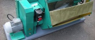
- machine bed
- gearbox
- traverse
- spindle head
- electrical equipment
- add-on legs (available at extra cost)
- accessories
- corner table (supplied for a special fee)
The frame is a rigid cast iron plate with longitudinal and transverse ribs on which a column is mounted. Screw 3 is designed to move the gearbox.
The gearbox is mounted on a column. The speeds are controlled using handles 4 and 3 (see Fig. 3). Handle 4 is intended for:
- enabling mechanical movement of the hose along the column
- sleeve clamp on column
- turning on the spindle
The traverse is installed in the cylindrical hole of the gearbox using pin I. The carriage 2 with the spindle head moves along the traverse guides.
The spindle head with the feed mechanism is housed in one housing.
Mechanical feed of the spindle occurs when turning handle 2 “From yourself”.
Fine feeding is carried out manually with the overload clutch in the off position by rotating handwheel 1.
Attached legs are used when the machine is used as a portable machine. They increase the stability of the machine. When using the machine as a stationary one (on a foundation), the legs are removed.
The corner table is used for fastening fixtures and parts.
Machine accuracy class N according to GOST 8-77.
The roughness of the treated surfaces, depending on the work performed, is R = 80-20 microns.
Radial drilling machines. General information.
Synonyms: radial drilling machine.
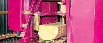
Moving large and heavy parts along the table plane causes great inconvenience and loss of time. Therefore, when processing a large number of holes in such parts, radial drilling machines are used. When working on them, the part remains stationary, and the spindle with the drill moves relative to the part and is installed in the required position.
Drilling machines are designed for drilling, countersinking, countersinking, reaming holes, trimming the ends of products and cutting threads with taps. They are used mainly in single and small-scale production, and some modifications of these machines are used in mass and large-scale production.
The main shaping movements during drilling operations are:
- v – the main thing is rotational movement
- s – feed movement of the machine spindle quill
The kinematic chains that carry out these movements have independent adjustment elements iv and is, through which the required rotation speed of the tool and its feed are set.
Auxiliary movements include:
- turning the traverse and securing it to the column
- vertical movement and fixing of the traverse at the desired height
- moving and securing the spindle head on the traverse
- switching speeds and spindle feeds
The main components of radial drilling machines are:
- foundation slab
- Column
- traverse (sleeve)
- mechanism for moving and clamping the sleeve on the column
- mechanism for moving and clamping the spindle head on the sleeve
- spindle head
The main parameters of the machine are the largest diameter of drilling holes in steel, overhang and maximum spindle stroke.
Adjustment of radial drilling machine 2N55
The design of the machine provides the ability to regulate individual mechanisms, the parts of which wear out during operation. Below are instructions for regulating the main mechanisms of the machine.
1. Adjustment of the spin and clamping of the machine column is carried out by turning the hollow screw 3 relative to the nut 7 (see Fig. 8).
For adjustment it is necessary;
- a) set the pressure in the system within 35..40 kg/cm2;
- b) supply oil under pressure into cavity “B” (squeeze);
- c) unscrew bolts 1 securing flange 2;
- d) rotate flange 2 to perform a spin (setting the axial stroke of the column within 0.4..0.5 mm);
- e) remove flange 2 from engagement with screw 3, align along the mounting holes and secure with screws I.
The adjustment should be made in such a way that when clamping the column, the plunger 21 does not reach the cover 25.
Otherwise, the full clamping force will not be achieved.
With a normally adjusted clamp, the rotating parts of the machine should not rotate from a force of less than 250 kg (for the machine mod. 2N55) and 150 kg (for the machine mod. 2N53) applied at the end of the sleeve in the horizontal plane. When spinning, rotation should be carried out with a force of no more than 5 kg.
2. The hose clamp on the column is adjusted by placing compensation washers 41 under the nuts 42 of bolts 30 (see Fig. 10). This method avoids re-drilling nuts and bolts. The nuts are tightened with the arm stationary. The clamp is considered sufficient if a 0.03 mm probe does not pass along the upper end of the sleeve barrel on the side opposite the cut.
3. The smooth movement of the hose along the column is controlled by nuts 32 (om.Fig. 10) while the hose is moving. The sleeve should move downwards without jerking.
4. The clamping of the drill head on the sleeve guides can be adjusted by turning the eccentric sleeve 11 (see Fig. 11). In the adjusted position, the bushing is locked with a special lock 21. The head is considered sufficiently secured if it cannot be moved from its place by a manual flywheel when applying a force of 25 kg.
5. If it is necessary to reduce the gap between the guides of the head body and the sleeve, loosen the eccentric axle nuts 8 (see Fig. 11) and turn them to set the required gap (up to 0.05 mm). In this case, the ease of moving the head along the sleeve should not be impaired.
6. Increased axial play of the spindle is eliminated by tightening nut 5 (see Fig. 18).
7. The adjustment of the spring that balances the spindle with the tool is carried out in the lower position of the spindle by turning worm 4 (see Fig. 19). After adjustment, you need to align one of the marks on the square of the worm with the arrows on the plate.
8. The feed force is adjusted by rotating screw 9 (see Fig. 15). After adjustment, tighten lock nut 10.
If, when working under load, the spindle stops rotating or the feed is turned off due to the operation of safety devices, it is necessary to stop the machine and check the condition of the tool (dullness, jamming in the conductor sleeve, etc.) or reduce the processing modes.
Instructions on measures to eliminate possible malfunctions related to electrical equipment, hydraulic equipment and lubrication systems are given in the relevant sections of this “Manual”.
Information about the rolling bearings used in machines is shown in Fig. 32 and in the specification.
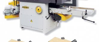
Made in China 4 Axis CNC Router
Specifications of Milling Machines
China 4 Axis CNC Router
Product Description
1.Adopting advanced industrial numerical control system, friendly human-machine interface, easy operation and reliable performance.
2.Suitable for processing aluminum alloy profiles, aluminum-wood composite profiles, copper and other light alloy profiles, and U-PVC profiles.
3.90°~0°~90° 4-axis simultaneous processing.
4. A set of clamping profiles completes milling, drilling, chamfering, grooving and other multi-functional precision machining.
5. High-strength welded structures are used to ensure high rigidity and high stability of the machine after thermal aging.
6.Imported high-precision linear guides, ball screw, rack and pinion and imported servo motors ensure smooth movement and high precision positioning and processing.
7. Adopt high quality imported high speed electric spindle with automatic tool changing to ensure processing stability, stable rotation noise and strong cutting ability.
8. Double table can process two or two profiles at the same time, interactive feeding and no interference.