Crank mechanisms
In a crank mechanism, a crankshaft is often used instead of a crank shaft.
This does not change the essence of the mechanism. The crankshaft can have either one elbow or several (b, c). In some crank mechanisms, it is necessary to change the stroke length of the slider. This is usually done with a crank shaft. Instead of a solid curved crank, a disk (faceplate) is mounted on the end of the shaft. The spike (the leash on which the connecting rod is put) is inserted into a slot made along the radius of the faceplate. By moving the tenon along the slot, that is, moving it away from the center or bringing it closer to it, we change the size of the slider's stroke.
The stroke of the slider in crank mechanisms is uneven. It is the slowest in places with backlash.
Rocker mechanisms
Instead of a slide, you can use a rod enclosed in a guide sleeve. To fit against the eccentric disk, the rod is equipped with a pressure spring. If the rod works vertically, its contact is sometimes achieved by its own weight.
For better movement along the disk, a roller is installed at the end of the rod.
Cam mechanisms
But there are disc cams of other designs. Then the roller slides not along the contour of the disk, but along a curved groove taken out from the side of the disk (b). In this case, a compression spring is not required. The movement of the roller with the rod to the side is carried out by the groove itself.
In cam mechanisms, swinging levers (c) are often used instead of a rod. Such levers allow you to change the length of the stroke and its direction.
The stroke length of the rod or lever of a cam mechanism can be easily calculated. It will be equal to the difference between the small radius of the cam and the large one. For example, if the large radius is 30 mm and the small radius is 15, then the stroke will be 30-15 = 15 mm. In a mechanism with a cylindrical cam, the stroke length is equal to the amount of displacement of the groove along the cylinder axis.
Due to the fact that cam mechanisms make it possible to obtain a wide variety of movements, they are often used in many machines. Uniform reciprocating motion in machines is achieved by one of the characteristic cams, which is called heart-shaped. With the help of such a cam, the shuttle bobbin of the sewing machine is wound uniformly.
Articulating lever mechanisms
The figure shows a hinged lever mechanism connected to other mechanisms. The lever mechanism receives the rocking motion from the crank and transmits it to the slider. The stroke length of a hinged lever mechanism can be increased by changing the length of the lever arm. The longer the arm, the greater will be its swing, and therefore the feed of the part associated with it, and vice versa, the smaller the arm, the shorter the stroke.
Reciprocating mechanism: types, device, application
The force from the source to the executive body can be transmitted in a variety of ways. Versions of execution have become quite widespread, the purpose of which is to convert rotational motion into reciprocating motion. A similar mechanism is installed very often today. Let's consider the varieties, scope and many other points in more detail.
Application area
The type of drive in question is found in a wide variety of areas. Wherein:
- Most often, the drive is installed in a machine designed for processing metal and wood.
- Some tools are also based on converting rotational motion into reciprocating motion. An example is a hammer drill or rotary hammers, which are common today.
- In industry you can find conveyors, structures for lifting and lowering various products.
The only significant drawback is the rather large size of the device. In addition, it is necessary to provide high-quality lubrication, since friction causes heat and wear.
Types of gears for translational motion
There are quite a large number of different devices that can be used to convert the transmitted force. The following options are widely used:
The information above indicates that there are simply a huge number of different options for the execution of mechanisms. The selection is made according to a variety of criteria that must be taken into account.
Ratchets
Ratchet mechanisms allow you to change the amount of periodic movements of the working parts of machines over a wide range. The types and applications of ratchet mechanisms are varied.
The ratchet mechanism (Fig. 10) consists of four main links: rack 1, ratchet (gear) 4, lever 2 and part 3 with a protrusion, which is called a pawl. A ratchet with teeth beveled in one direction is mounted on the driven shaft of the mechanism. On the same axis with the shaft, a lever 2 is hinged, rotating (swinging) under the action of the drive rod 6. A pawl is also hinged on the lever, the protrusion of which has a shape corresponding to the cavity between the teeth of the ratchet.
During operation of the ratchet mechanism , lever 2 begins to move. When it moves to the right, the pawl slides freely along the rounded part of the ratchet tooth, then, under the influence of its gravity or a special spring, it jumps into the cavity and, resting against the next tooth, pushes it forward. As a result of this, the ratchet, and with it the driven shaft, rotates. Reverse rotation of the ratchet with the driven shaft when the lever with pawl 3 is idling is prevented by a locking pawl 5, hinged on a fixed axis and pressed against the ratchet by a spring.
The described mechanism converts the rocking motion of the lever into intermittent rotational motion of the driven shaft.
DIY reciprocating mechanism
You can save a lot by creating a reciprocating mechanism with your own hands. In some cases it is made from a drill, in others an electric motor is used to transmit the rotating torque.
We will name the following points as features:
In general, we can say that the task under consideration is quite difficult to perform. That is why the work should be carried out exclusively by professionals who can carry out complex calculations and also produce the required parts.
Eccentric and cam mechanisms
The diagram of the eccentric mechanism is shown in Fig. 9, b. The eccentric is a round disk, the axis of which is offset relative to the axis of rotation of the shaft carrying the disk. When shaft 2 rotates, eccentric 1 acts on roller 3, moving it and the associated rod 4 upward. The roller is returned down by spring 5. Thus, the rotational movement of shaft 2 is converted by an eccentric mechanism into translational movement of rod 4.
Cam mechanisms are widely used in automatic machines and other machines to implement an automatic work cycle. These mechanisms can be with cylindrical disk and mechanical cams. Shown in Fig. 9, the mechanism consists of a cam 1 with a groove 2 of complex shape at the end, in which a roller 3 is placed, connected to the slider 4 by means of a rod 5. As a result of the rotation of the cam 1 (in its different sections), the slider 4 receives different speeds of a rectilinear reciprocating movements.
Reciprocating mechanism how to make
Crank mechanisms
In a crank mechanism, a crankshaft is often used instead of a crank shaft. This does not change the essence of the mechanism. The crankshaft can have either one elbow or several (b, c).
A modification of the crank mechanism can also be an eccentric mechanism (d). The eccentric mechanism has no crank or knees. Instead, a disk is mounted on the shaft. It is not mounted in the center, but offset, that is, eccentrically, hence the name of this mechanism - eccentric.
In some crank mechanisms, it is necessary to change the stroke length of the slider. This is usually done with a crank shaft. Instead of a solid curved crank, a disk (faceplate) is mounted on the end of the shaft. The spike (the leash on which the connecting rod is put) is inserted into a slot made along the radius of the faceplate. By moving the tenon along the slot, that is, moving it away from the center or bringing it closer to it, we change the size of the slider's stroke.
Connections of parts and their types
The placement and installation of mechanical gears in the machine, as well as their interconnection, are provided by the parts that are used to connect them during assembly.
Rice. 16. Diagram of the most common types of connections
The main types of connections are shown in the diagram (Fig. 16). The types of connections are identified by their names on the diagram. Connections of parts in a machine or mechanism, depending on their design, can be divided into movable and fixed, which in turn can be presented as detachable and permanent connections.
Detachable or dismountable are connections that can be disassembled without much difficulty and without damaging the mating or fastening parts. For example, connections using clearance fits and transition fits, threaded connections, etc.
One-piece or non-separable are connections whose disassembly during operation is not provided for and is difficult, requires great effort and is accompanied by damage to the mating or fastening parts, or the adhesive substance.
Fixed, non-separable connections are made by riveting, soldering, interference fits, gluing, pressing, cold stamping and other methods. Such connections are distinguished by their strength and stability of the relative position of the parts being connected.
Fixed, dismountable connections are made using transitional fits and keys, screw connections, connections using pins, conical connections, wedges and other connections.
Examples for module 1 topics
1. Let us determine the angular speed of rotation of the motor shaft (see formula (1.4)):
2. Let's find the rotation transmission ratio (see formula (1.1)):
.
3. Let's select a worm gear.
Option 1. If the number of turns of the worm
, then the number of teeth of the worm wheel from formula (1.11)
.
Option 2. If the number of turns of the worm
=2, then the number of teeth of the worm wheel
The gear drive should reduce the rotation speed of shaft 4 (see Fig. 1.4) by 3 times. Determine the number of wheel teeth
, if the number of gear teeth
= 25.
Number of wheel teeth from formula (1.6)
.
Rice. 1.14. For example 3
Determine the gear ratio of the mechanism shown in Fig. 1.14, for a given number of wheel teeth:
=22,
=77,
=25,
=50. Find the angular velocity and rotation frequency of drive shaft 1 if shaft 3 rotates at a frequency
=300 rpm.
1. Let's determine the gear ratio of the gear mounted on shafts 1 and 2
2. Determine the gear ratio of the gear mounted on shafts 2 and 3
3. Gear ratio of the mechanism
4. Find the rotation speed of shaft 1:
rpm
5. Calculate the angular speed of rotation of shaft 1:
Kinematic pairs, kinematic diagram
To consider the process of transferring mechanical energy inside a machine, interacting parts and assembly units are usually considered in pairs.
A kinematic pair is a movable connection of two contacting links. The properties of the pair depend on the shape of the surfaces with which the links come into contact during their possible relative movement. A pair in which there is no relative motion between the contacting links is called a joint. Links can consist of individual parts or several parts fixedly fastened to each other. For the graphic representation of kinematic pairs, symbols are used (Table 1).
Table 1. Symbols of kinematic pairs of mechanical transmissions
| Flat belt transmission: a - open; b - open with tension roller | Bevel gear - gearing between shafts whose axes intersect (designation without specifying the type of teeth) | ||
| Transmission by V-belts | Rack and pinion transmission (designation, without specifying the type of teeth) | ||
| Chain transmission a - general designation without specifying the type; 6 - roller; c - silent | Worm gear with cylindrical worm | ||
| Gear transmissions (cylindrical) between parallel shafts: a - external gearing (designation without specifying the type of teeth) | Helical gear transmission | ||
| The same: b - with helical and straight teeth | Sliding screw-nut transmission: a - one-piece; b - detachable | ||
| The same: in - internal gearing | Ratchet transmission |
In kinematic pairs, it is necessary to distinguish between leading and driven links. The link that sets the movement in a kinematic pair is called the leading one, and the link that receives the movement is called the slave or sometimes the worker.
The system of movably connected links is a kinematic chain. If a kinematic chain is designed to obtain very specific movements of the driven links, it is called a mechanism.
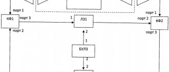
Kinematic chains drawn using the symbols of kinematic pairs are called kinematic diagrams. Kinematic diagrams are a system of sequentially located interacting links connecting the working links with the source of motion (Fig. 13).
Figure 13. Simplified kinematic diagram of a screw-cutting lathe
In Fig. Figure 13 shows a simplified kinematic diagram of thread cutting on a screw-cutting lathe. The main movement (rotation of the spindle with workpiece 1) is carried out from the electric motor M through a belt drive with pulleys d1 and d2, gears z1 and z2, replaceable gears a' and b', gears z3 and z4. The longitudinal movement of the cutter (feed movement) is produced by transmitting rotation from the spindle through gears z5 and z6; screw bevel wheels z7 and z8, z9 and z10; replaceable gears a and b, c and d to the lead screw 3. The rotational movement of the lead screw is converted into translational movement of the support 2 with the cutter.