Mechanisms are indispensable assistants to a person in any of his activities. But the mechanism itself is just a collection of parts. In order for it to work, it must be provided with energy. It is supplied from a separate device - an engine or power plant using special mechanisms called gears. It just so happened historically that rotational motion is most often used in technology, although other types are also used. During the process of energy transition, it can change; this change occurs in accordance with the transmission ratio the mechanism has.
About what happens
The simplest example of transmission is from the rotating wheel of a water mill to a millstone. In this case, there is often a change in the initial energy received by the wheel from the flowing water, in magnitude and direction. The magnitude of this change will be determined by the gear ratio. It describes one of the most important characteristics of energy conversion during rotational motion, defined as the ratio of the frequency or rotation speed of the element receiving energy to the same parameters of the element giving off energy.
In other words,
the gear ratio describes how the original energy received from an engine or any other energy source (water wheel, wind wheel, turbine, etc.) changes as it is transmitted. Throughout the history of technological development, humanity has created a wide variety of transmissions, for each of which there is a gear ratio that is a quotient of the speed of the driving link divided by the speed of the driven link.
Advantages and disadvantages
Worm final drive Each type of gear connection has its pros and cons. Let's look at them:
- Cylindrical main gear. The maximum gear ratio is limited to 4.2. A further increase in the tooth ratio leads to a significant increase in the size of the mechanism, as well as an increase in the noise level.
- Hypoid main gear. This type is characterized by low tooth load and reduced noise level. In this case, due to the displacement in the meshing of the gears, sliding friction increases and efficiency decreases, but at the same time it becomes possible to lower the driveshaft as low as possible. Gear ratio for passenger cars – 3.5-4.5; for freight – 5-7;.
- Bevel main gear. Rarely used due to its large size and noise.
- Worm main gear. This type of gear connection is practically not used due to the complexity of manufacturing and the high cost of production.
Belt drive ratio
A belt drive refers to two pulleys that are connected by a belt, as shown in the figure. It is possible that it was one of the first methods used by man. The material used to make the belt changed, its shape changed, but the gear ratio remained unchanged, defined as the frequency of dividing the speed of the drive shaft by the speed of the driven one, or as a result of dividing the number of revolutions of these shafts (n1/n2 or ω1/ω2). For a belt drive, it can be calculated using the diameters (radii) of the pulleys. The gear ratio in this case is also determined as the quotient of the division of revolutions.
If, during energy conversion, the speed decreases, that is, the gear ratio is greater than 1, then the transmission will be reduction, and the device itself is called a gearbox. If the result is less than one, then the device is called a multiplier, although it also functions as a reducer, only a step-down one. The gear ratio of the gearbox allows you to reduce the number of revolutions (angular velocity) coming from the drive shaft to the driven shaft, while increasing the transmitted torque.
This property of the gearbox makes it possible for engineers, when designing various devices, to change the parameters of the transmitted energy, and the gear ratio of the gearbox serves as a powerful tool in solving the problem.
Despite its considerable age, the belt drive is still used on cars; it is used as a drive for a generator, a gas distribution mechanism, and also in some other cases.
Primary requirements. Modern tendencies
The main gears are subject to many requirements, the main ones being:
- Reliability;
- Minimal maintenance required;
- High efficiency indicators;
- Smooth and silent;
- Minimum possible overall dimensions.
Naturally, there is no ideal option, so designers have to look for compromises when choosing the type of final drive.
It is not yet possible to abandon the use of final drives in transmission designs, so all developments are aimed at increasing performance indicators.
It is noteworthy that changing the operating parameters of the gearbox is one of the main types of transmission tuning. By installing gears with a changed gear ratio, you can significantly influence the dynamics of the car, maximum speed, fuel consumption, load on the gearbox and power unit.
Finally, it is worth mentioning the design features of dual-clutch robotic gearboxes, which also affects the final drive design. In such gearboxes, paired and unpaired gears are separated, so there are two secondary shafts at the output. And each of them transmits rotation to its own drive gear of the main gear. That is, in such gearboxes there are two driving gears, and only one driven gear.
DSG gearbox diagram
This design feature allows you to make the gear ratio on the gearbox variable. To do this, only drive gears with different numbers of teeth are used. For example, when using a number of unpaired gears, to increase traction, a gear is used that provides a larger gear ratio, and the gear of a paired row has a lower value of this parameter.
The main gear of a car is a transmission element, in the most common version, consisting of two gears (driven and driven), designed to convert the torque coming from the gearbox and transmit it to the drive axle. The design of the main gear directly affects the traction and speed characteristics of the vehicle and fuel consumption. Let's consider the device, principle of operation, types and requirements for the transmission mechanism.
Chain transmission ratio
In such a belt drive, the belt can be replaced with a chain, in which case the pulleys must also be replaced with sprockets. The resulting transmission is called a chain transmission, it is familiar to everyone, because this is exactly what is used on bicycles. For it, the gear ratio is determined in the same way as for a belt, but you can also use the ratio of the number of teeth on the sprockets (drive and driven). However, with this calculation, the gear ratio will be inverse, that is, the gear ratio is determined by dividing the number of teeth of the driven sprocket by the number of teeth of the drive sprocket (z2/z1).
A distinctive feature of the chain drive is the increased noise level, as well as wear when operating at high speeds, so if it is necessary to use it, it is best to install it after reducing the speed. In a car, it is possible to use a chain drive to drive a timing belt, however, the limitation of this application is the increased noise level during its operation.
Explosion-proof versions of gearmotors
Geared motors of this group are classified according to the type of explosion-proof design:
- “E” – units with an increased degree of protection. Can be used in any operating mode, including emergency situations. Enhanced protection prevents the possibility of ignition of industrial mixtures and gases.
- “D” – explosion-proof enclosure. The housing of the units is protected from deformation in the event of an explosion of the gear motor itself. This is achieved due to its design features and increased tightness. Equipment with explosion protection class “D” can be used at extremely high temperatures and with any group of explosive mixtures.
- “I” – intrinsically safe circuit. This type of explosion protection ensures the maintenance of explosion-proof current in the electrical network, taking into account the specific conditions of industrial application.
Gear ratio
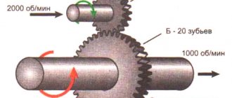
This is the name of a mechanism that uses wheels with teeth in mesh. It is considered the most rational and in demand for mechanical engineering. There are many different options for manufacturing such wheels, differing in the location of the axles, the shape of the teeth, the method of their engagement, etc. As in the case of a chain gear, for a gear gear the gear ratio is determined by dividing the number of gear teeth (z2/z1).
The variety of options for constructing gear drives makes it possible to use them in different conditions, from low-speed gearboxes to high-precision drives.
Gear transmission is characterized by:
- constant gear ratio;
- compactness;
- high efficiency;
- reliability.
One of the types of gear transmission is considered to be a worm gear. It is used in cases where torque is transmitted between crossing shafts, for which an element such as a worm is used, which is a screw of a special design with a thread. To determine the gear ratio of the worm gear, divide the number of teeth of the (worm) wheel z2 by the number of worm thread starts z1.
Determination methods
There are several ways to determine the gear ratio:
- theoretical;
- practical;
- calculated
The first, simplest, method is theoretical. Usually, in order to find out the necessary information, you just need to look at the car’s instructions, where detailed tables are indicated. Most cars contain such information in the Vin number, where it is encrypted, but it is easy to find out. Russian-made cars usually have a standard set of standard gearbox models. This greatly simplifies the replacement process.
It's a different matter when it is necessary to replace only a separate part of the assembly. Usually, when a car has had several owners, it is not known how many times the gearbox has been replaced and what model is currently installed. This is often quite easy to do, since they try to put the necessary information in places that are most convenient for viewing.
The practical method of determining the gear ratio is more complex and requires direct intervention in the vehicle mechanism. Let's look at the detailed step-by-step instructions:
- The first thing you need to do is find out what model is installed on your car. There are several types that differ depending on the type of gear transmission, there are gear, chain, screw, hypoid, wave and fractional. In any case, the gear ratio is calculated as the ratio of the rotation speed of the driven and drive shafts. If the above data is known, you will have to resort to disassembling the node.
- It is necessary to disconnect the gearbox from the housing and related components and open the cover to have an overview of the structural elements. With the help of such manipulations, you can find out exactly which element of the gearbox you should start from when calculating.
- Then calculate the gear ratio based on the type of unit. If the transmission is geared, then the calculation is quite easy; in this case, the calculated indicator is equal to the ratio of the number of teeth of the driven gear to the teeth of the drive gear. You just need to calculate the specified parameters.
- If the transmission is belt driven, the calculation is made by the ratio of the diameter of the drive pulley to the driven one, or vice versa. The calculation is always carried out from the larger number. With a chain drive, you need to count the number of teeth of the drive and driven sprocket, and calculate the ratio of the larger to the smaller. With a worm gear, the number of runs on the worm and the teeth on the worm wheel are counted, after which the ratio of the second number obtained to the first is calculated.
To do this, you need to use a special measuring device - a tachometer, which measures the rotation speed of the engine drive shaft and the shaft that drives the wheels. The ratio of the first indicator to the second will help to accurately determine the gear ratio.
You can do this easier by calculating the torque of the gearbox by rotating the wheel. The drive axle must be raised on supports. The initial position of the wheel and drive shaft is recorded; this can be done using simple marks. Then you should rotate the wheels until the marks coincide and separately count the number of revolutions of the shaft and wheel. For these purposes, it is rational to use someone else's help.
After collecting all the necessary information, you need to divide the number of revolutions of the drive shaft by the number of rotations of the wheel. To get an accurate result, you need to carefully consider each stage of the procedure, since even the slightest inaccuracy in measurement can critically affect the final result.
Planetary gear
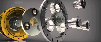
This type of gear train contains wheels with geometric axes that can move. What it is can be understood from the figure below. In fact, this is already the design of a kind of planetary gearbox, which includes a certain number of gears that interact with each other. Each of them has its own name - sun, crown, satellite.
For such a planetary gearbox, the change in torque depends on which of its gears is stationary, to which the torque is applied, and from which it is removed.
Whenever a planetary gearbox is used, one of its three elements will be stationary. This planetary option for constructing gears, in relation to a simple gear or belt, has the opportunity to obtain a significant change in torque with a small number of wheels and the dimensions of the device. In a car, such a planetary device has its own scope of application - as part of an automatic transmission, as well as in hybrid vehicles, to ensure the joint operation of the internal combustion engine and the electric motor. Planetary gearboxes are widely used in tracked vehicles.
Gearbox type
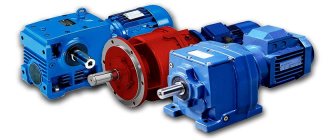
The presence of a kinematic drive diagram will simplify the choice of gearbox type. Structurally, gearboxes are divided into the following types:
Single-stage worm gear with crossed input/output shaft arrangement (angle 90 degrees).
Two-stage worm gear with perpendicular or parallel arrangement of the axes of the input/output shaft. Accordingly, the axes can be located in different horizontal and vertical planes.
Cylindrical horizontal with parallel input/output shafts. The axes are in the same horizontal plane.
Cylindrical coaxial at any angle. The shaft axes are located in the same plane.
In a bevel-helical gearbox, the axes of the input/output shafts intersect at an angle of 90 degrees.
IMPORTANT! The spatial location of the output shaft is critical to a number of industrial applications.
- The design of worm gearboxes allows them to be used in any position of the output shaft.
- The use of cylindrical and conical models is often possible in the horizontal plane. With the same weight and dimensional characteristics as worm gearboxes, the operation of cylindrical units is more economically feasible due to an increase in the transmitted load by 1.5-2 times and high efficiency.
Table 1. Classification of gearboxes by number of stages and type of transmission
| Gearbox type | Number of steps | Transmission type | Axes location |
| Cylindrical | 1 | One or more cylindrical | Parallel |
| 2 | Parallel/coaxial | ||
| 3 | |||
| 4 | Parallel | ||
| Conical | 1 | Conical | Intersecting |
| Conical-cylindrical | 2 | Conical Cylindrical (one or more) | Intersecting/crossing |
| 3 | |||
| 4 | |||
| Worm | 1 | Worm (one or two) | Crossbreeding |
| 1 | Parallel | ||
| Cylindrical-worm or worm-cylindrical | 2 | Cylindrical (one or two) Worm (one) | Crossbreeding |
| 3 | |||
| Planetary | 1 | Two central gears and satellites (for each stage) | Coaxial |
| 2 | |||
| 3 | |||
| Cylindrical-planetary | 2 | Cylindrical (one or more) Planetary (one or more) | Parallel/coaxial |
| 3 | |||
| 4 | |||
| Cone-planetary | 2 | Conical (single) Planetary (one or more) | Intersecting |
| 3 | |||
| 4 | |||
| Worm-planetary | 2 | Worm (one) Planetary (one or more) | Crossbreeding |
| 3 | |||
| 4 | |||
| Wave | 1 | Wave (one) | Coaxial |
About the main couple
Almost all types of gears are used in a car - the torque from the engine passes through a chain of various devices and undergoes changes, starting from the gearbox, the main pair, and ending with the wheels of the car. All gear ratios for the gearbox and the main pair directly affect the dynamics of the car. Therefore, with the aim
- reducing switching frequency;
- possibility of movement during quiet driving at low engine speeds;
- increasing the upper threshold of driving speed,
gear ratios, including for the main pair, must be reduced. To improve overclocking dynamics, everything should be the other way around.
The operation of various mechanisms and devices, including in a car, cannot occur without converting the energy used, both in magnitude and direction. The gear ratio helps to evaluate and calculate the magnitude of the required change, as well as its consequences.
What else is worth reading
Types of gearboxes
Engine turbocharging
Types of parking sensors
Timing belt
Rear axle gearbox
Ratchet mechanism
In many machines and units, not only continuous rotational motion is used, but also intermittent rotation, which is carried out using a ratchet, pawl and lever.
In addition to rotation, the ratchet mechanism also performs a safety function. So, for example, in lifting winches, the ratchet together with the pawl prevent the drum from turning in the opposite direction, reliably fixing it in the required spatial position.
The types of mechanical transmissions considered are used in almost any sector of the national economy and are widely used due to their technical capabilities.
2.3. Determination of power and torque on shafts
Gearbox input shaft rotation speed n 1
=
n dv u
o.p.
The rotation speed of the gearbox output shaft is determined taking into account the accepted standard
gear ratio u st
The powers (kW) transmitted by the shafts are determined taking into account the efficiency of the constituent links of the kinematic chain (see Fig. 4):
R
1 = Р dv ∙ η op ∙ η p Р
2 =R
1
∙ η zp ∙ η p ∙η m
(2.8)
Torques (N∙m) on the gearbox shafts can be determined by the following dependencies:
for input shaft —
, (2.9)
where T i
– torque transmitted by the shaft, N. m;
[ τ cr
] – permissible torsional stresses;
[ τ cr
]=15…20 MPa.
The obtained values of the diameters of the gearbox shafts should be rounded to the nearest larger value from the range of normal linear dimensions according to GOST 6636-69. For the convenience of further calculations, the found gearbox parameters are summarized in the table:
| u ed | n i , rpm | R i , kW | T , N∙m | d i , mm |
Transmission tuning. How to choose gear ratios for a gearbox?
Most of the technologies used in transmission tuning are proven in motorsports.
The transmission of any, especially a sports car, is the most important mechanism for realizing the dynamic characteristics of the engine. Even with a relatively weak engine, the car can be fast due to correctly selected gear ratios. In motorsport, synchronized (as on 'road' cars) and non-synchronized (cam) gearboxes are used. Based on the shifting principle, they are divided into conventional (H-pattern) and sequential (with sequential gear selection, like on motorcycles).
In cars of a fairly serious level of preparation, cam gearboxes are used. They have a number of advantages - they can withstand higher loads (due to the shape of the tooth and the gear-cam clutch engagement), allow experienced pilots to spend less time changing gears due to incomplete squeezing of the clutch or without squeezing the clutch at all, they do not destroy synchronizers (which are simply No).
Operational coefficient (service factor)
Service factor (Sf) is calculated experimentally. The type of load, daily operating duration, and the number of starts/stops per hour of operation of the gearmotor are taken into account. The operating coefficient can be determined using the data in Table 3.
Table 3. Parameters for calculating the service factor
| Load type | Number of starts/stops, hour | Average duration of operation, days | |||
| <2 | 2-8 | 9-16h | 17-24 | ||
| Soft start, static operation, medium mass acceleration | <10 | 0,75 | 1 | 1,25 | 1,5 |
| 10-50 | 1 | 1,25 | 1,5 | 1,75 | |
| 80-100 | 1,25 | 1,5 | 1,75 | 2 | |
| 100-200 | 1,5 | 1,75 | 2 | 2,2 | |
| Moderate starting load, variable mode, medium mass acceleration | <10 | 1 | 1,25 | 1,5 | 1,75 |
| 10-50 | 1,25 | 1,5 | 1,75 | 2 | |
| 80-100 | 1,5 | 1,75 | 2 | 2,2 | |
| 100-200 | 1,75 | 2 | 2,2 | 2,5 | |
| Operation under heavy loads, alternating mode, large mass acceleration | <10 | 1,25 | 1,5 | 1,75 | 2 |
| 10-50 | 1,5 | 1,75 | 2 | 2,2 | |
| 80-100 | 1,75 | 2 | 2,2 | 2,5 | |
| 100-200 | 2 | 2,2 | 2,5 | 3 |
Determination of power by current
If you “in the field” do not have the above tables at hand, but do have current clamp meters, you can calculate the power of the electric motor based on the results of measurements when it is operating under voltage.
To do this, turn off the power switch of the unit and open the tank. The wires in it are usually laid very tightly, in order to get to them with pliers, you will have to temporarily straighten them and separate them from each other.
There is no need to remove anything from the terminals themselves. After this, turn on the electric motor and let it run under load for a few minutes (not idling!)
Use a current clamp to grasp one of the phases and record the measurement data.
In addition to the current, you also need to know the actual voltage. You take measurements between the phases of the incoming power cable.
Next, to calculate the power, use the well-known formula:
By substituting the data into it (U in kilovolts!, and the current in amperes), you will find out the total power of the engine in kVA. It should be taken into account that the power of the electric motor does not depend on the connection diagram of the stator windings, be it a triangle or a star.
You will simply receive different data on current and voltage, but the value of the power itself will remain the same.
In order to find out the power of the electric motor in kW, i.e. on the shaft, it is enough to multiply the resulting value by cosϕ (power factor = 0.75-0.85) and by efficiency (0.75-0.95).
If you do not have exact data on these values (which is most often observed), substitute the average parameters:
cosϕ=0.8
ⴄ=0.85
Round the result to a whole number and find out the required power.
https://youtube.com/watch?v=vGJJl3SL4DQ%3F
Sources – //cable.ru, Kabel.RF
