Conveyor design features
If the work of the enterprise involves heavy loads, then it is necessary to use equipment that will withstand the large weight of the product.
Therefore, in such cases, chain conveyors are preferred. They are used to move products in inclined and horizontal positions, and to organize reverse directions. They differ from tape ones in that they are bulkier, more complex, and more massive. However, the chain conveyor has great application possibilities, which determines its popularity. Its traction and load-carrying element is one or more chains that move along special guides. The movement occurs thanks to a frame with smooth guides and drive and tension sprockets attached to it. Chain conveyors look like a kind of box, inside of which there is a partition. It may differ in the presence of one or two parallel circuits (depending on the design load and purpose). The rollers have a thrust flange or a cylindrical surface. The transported cargo is moved by the upper or lower branch, depending on the type of device.
There are the following types of chains:
- rollers with smooth rollers;
- roller;
- rollers with flanges on rollers.
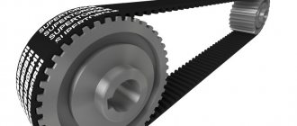
It is worth noting that any flail mechanisms for chain conveyors can be produced in dismountable or non-dismountable form. The drive consists of one/two sprockets that are mounted on the drive shaft. Due to the tension of the chain, torque is transmitted from the drive wheel to the driven wheel.
The main design feature of the conveyor is the ability to move large and long loads. If a plate chain is used, then it is possible to transport piece goods of any weight or size.
The chain conveyor can be operated even in high temperature conditions if it does not contain composite or polymer materials. The conveyor can be increased or decreased to the required length thanks to its modular design. The maximum load reaches several tons.
What types of chains are used for chain conveyors:
- box;
- drives made of stainless steel;
- roller;
- bushing-roller;
- lamellar.
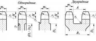
By design, depending on the characteristics of the cargo:
- one-two-three-four-row chains;
- with flanges on rollers for chain positioning;
- with rollers for accumulation areas;
- with special pads for fragile products;
- with plates that are needed to secure additional elements.
Types of chain conveyors
Among the variety of designs of chain conveyors, the following main types are distinguished:
- Vertical. Designed to lift payloads from level to level vertically or at a steep angle. They are equipped with grippers, containers or open areas for placing the material or objects being moved. Their advantage lies in their small footprint and the possibility of continuous supply of cargo. The control of such devices, unlike elevators, does not require constant intervention by an operator or an automated system.
- Horizontal. They are used for transporting bulk sludge and semi-liquid substances, both finely dispersed and lumpy. Enclosed, dust-proof chain conveyors are used to move fine materials.
- Inclined. Slope up to 45° is allowed. They are equipped with protective sides to prevent the load from falling from a height.
Horizontal conveyors are also used to move carcasses in freezers and feed parts to the main assembly conveyor.
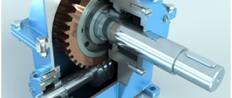
Construction of chain conveyors
The main components, or sections, included in the design of the device are as follows:
- Driven. This is the frame on which the drive shaft and drive gear are mounted. The drive is also located here - an electric motor and a gear-type reducer that transmits torque to the drive shaft.
- Tension. This is the end of the frame opposite to the leading one. The driven VAZ and gear are fixed in a special spring-loaded bracket. Its distance from the drive shaft is adjusted using a worm drive. The further the driven shaft moves away from the drive shaft, the higher the chain tension.
- Intermediate. It is a frame section between the drive and tension sections. If the conveyor is long enough, passive support shafts with chain-supporting gears can be installed on it. This avoids chain sagging. The number of support shafts is determined during engineering calculations and construction of the conveyor drawing. In scraper type devices there is no need for support shafts.
- Working body. It's the chain itself. Its links can be forged, welded or assembled, like a bicycle chain. On scraper chain conveyors, shields perpendicular to it are attached to the chain, which, moving through the mass of the product, carry it along with them.
For conveyors operating in hot shops, special steel grades are used; electrical equipment, gearboxes and shaft bearings must also be selected in a heat-resistant design.
The load on a chain conveyor can be placed either from above the working branch, on platforms, containers, etc., or from below - on hooks or magnetic hangers.
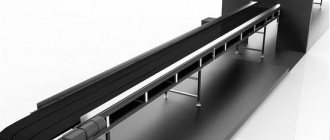
Rice. 1. Scheme of a plate conveyor 1 - transporting body; 2 - drive drum; 3 - chain; 4—bed guides; 5 - tension ram
Rice. 2
—
In chain conveyors, the traction element is chains of various types, both plate chains in accordance with GOST 588-64 and welded chains in accordance with GOST 2319-70. The most common are plate-type bushing-roller chains. Chain conveyors can be used at high temperatures, as well as for working with very coarse and large-piece materials, when the use of belt conveyors becomes impractical. The chain allows for convenient and reliable fastening of load-carrying and running elements of the conveyor, ensures reliable transmission of traction force by engaging the chain with a sprocket and has low elongation under load.
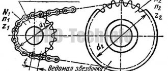
Rice. 3. Conveyor chains: a - plate bush-roller chain; b — bushing-roller chain (with 1 flanged and 2 flanged rollers); c - bushing-roller chain with curved plates
A lower value of the unevenness coefficient is accepted with increased precision in the manufacture of the chain and installation of the conveyor.
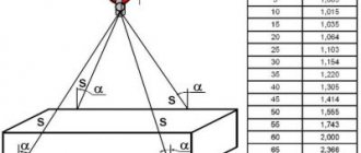
The safety factor k depends on the purpose and degree of responsibility of the machine, the type of its route, and operating conditions. Typically, for conveyors of non-essential purposes without vertical or strongly inclined branches, k - 6 - 7 are taken; for critical purpose conveyors (for example, for escalators), as well as for conveyors with highly inclined sections, k - 8 - 10.
In addition to this method of calculation based on the average safety factor, the determination of the safety factor using the differential method is increasingly used, when the total safety factor is made up of the product of several coefficients, each of which takes into account the influence of individual factors or a group of factors on the load-bearing capacity of the chain*.
Simultaneously with the transportation of cargo on a chain conveyor, various technological operations can be performed. Chain conveyors are especially widely used in assembly shops (assembly conveyors), as well as in automatic workshops and automatic factories, since a chain conveyor can be easily adapted to perform a given technological process and automate its operation according to a given program. Chain conveyor designs are even more varied than belt conveyor designs. All chain conveyors can be divided into conveyors installed on the floor and overhead conveyors, when the working elements of the conveyor move along a special overhead track.
Chain conveyors can consist of two parallel chains or just one endless chain. During its movement, the chain is supported by rollers, and these rollers can be installed stationary (like the rollers of belt conveyors) or they can move along with the chain. In the latter case, the running rollers move along special guides.
Rice. 4. Scheme of a bucket conveyor: 1 - tension sprocket; 2 - guides; 3 - traction chain; 4— buckets; 5 - drive sprocket; b—unloading device
To move cargo, conveyors are equipped with plates that form the conveyor belt, or with buckets, cradles, special grabs, carts, etc. Bucket chain conveyors are widely used in various fields of industry (coal, chemical, cement, etc.). The buckets of the bucket conveyor are hingedly suspended from two plate-bushing traction chains and the center of gravity of the bucket is always located below the suspension axis, which ensures a stable position of the bucket during its movement and automatic return to its original position after tipping over during unloading.
The advantages of bucket conveyors are the ability to transport not only horizontally, but also along an inclined section and even vertically, the simplicity and convenience of unloading the conveyor at any point along the route, the ability to transport hot cargo, and the absence of additional crushing of the cargo during transportation.
The disadvantages of bucket conveyors are the large weight of the chassis and the high cost of the conveyor. In addition, it should be noted that when moving at high speeds (1 - 1.5 m/sec), the buckets sway, which increases the dynamic forces in the structure and leads to the scattering of the load. Therefore, bucket conveyors usually operate with movement speeds in the range of 0.15–0.4 m/sec, with larger values being assumed for small pitch chains when the dynamic load decreases.
Conveyor buckets are usually made of sheet steel with a thickness of 2 to 6 mm, using electric welding and suspended from a chain on axles. According to the method of arrangement of buckets, conveyors with spaced and closed buckets are distinguished. When the buckets are closed, the gap between the buckets is blocked by special canopies attached to the buckets, and they do not interfere with the bucket tipping in one direction.
Rice. 5. Chain conveyor bucket suspensions: a - spaced; b - closed suspension; c - on the through axis; g - on two axles
The bucket filling coefficient f is taken to be in the range of 0.7–0.8, with lower values accepted for lumpy loads.
Buckets are unloaded by installing stops or special unloading tires near the unloading point. The buckets reach the stops and tip over, emptying the load. After emptying, the buckets return to their original position.
Rice. 6. Unloading buckets: a - installing a trolley with unloading tires; b - installing the stop
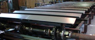
To supply cargo in a continuous flow, as well as to transport piece goods, plate chain conveyors are used, bending in a vertical or horizontal plane, in which the chains are connected by special wooden or metal trays. The apron conveyor consists of a drive station, a tensioning station and a lamellar roller chain with trays moving along a special path supporting the working and idle branches of the conveyor. Unloading is done from the conveyor belt as it passes through the drive sprockets, and loading can be done through the loading tray anywhere along the working branch of the conveyor. In the front part, the trays have curves (relative to their rotation axis), creating continuity of the conveyor belt as they go around the sprockets.
Flat flat decking is used mainly for transporting piece goods. To increase the cross-section of bulk material, and therefore increase the productivity of the conveyor, movable sides, that is, moving along with the conveyor belt, or fixed sides are used. The blade plates are attached to the links of the traction chain using bolts, rivets or welding. On a belt without sides, it is considered that the load is located in a triangle, as on a belt conveyor with a flat belt.
Rice. 7. Plate conveyor
Rice. 8. Sections of apron conveyor
Rice. 9. Cross section of bulk cargo on the deck of an apron conveyor: a - without sides; b - with movable sides; c - with fixed sides
The speed of movement of apron conveyors is 0.05-0.6 m/sec, depending on their purpose and the nature of the load.
Apron conveyors are widely used in industry for transporting various piece and bulk cargoes. Often, simultaneously with transportation, the cargo is subjected to technological operations - heat treatment, washing, drying, painting, etc. Since the apron conveyor belt is more durable than the conveyor belt, more heavy, lumpy and abrasive loads, as well as high-temperature loads.
Rice. 10. Scraper conveyor: 1 - tension device; 2 — traction articulated roller chain; 3 - scrapers; 4 — drive station: 6 — valve of the unloading device; 6 — chute of the working branch of the conveyor
Varieties of plate conveyors include various conveyors for filling molds and escalators used in subways and in institutions. Since plate conveyors are very heavy - both the load and the web move in them, to transport materials, the crushing of which does not reduce their quality, scraper conveyors are used, in which the material moves along a stationary chute by dragging with the help of scrapers connected to a moving chain.
Scraper conveyors are used to transport various dusty, granular and lump materials. The troughs of the scraper conveyor are made of wood or iron or wood covered with sheet iron. The shape of the gutter can be very different. However, in the trench shown in Fig. 11a, material can get stuck in corners, increasing resistance to movement. Therefore, the gutter shapes shown in Fig. 11, b, f, is preferable.
The conveyor scraper is made of sheet steel 3-8 mm thick. Sometimes, to increase its service life, the lower edge of the scraper, which rubs along the groove, is overlaid or welded with a strip of wear-resistant material (for example, manganese steel). In some cases, plastic scrapers are used. The pitch of the scrapers is determined depending on the size of the pieces of cargo, the angle of repose, the height and shape of the scraper, and the pitch of the chain. The selected scraper pitch should provide the best possible filling of the space between the scrapers and is usually taken to be equal to two chain pitches.
Rice. 11. Shape of gutters and scrapers of the scraper conveyor: a - rectangular; b - trapezoidal; c - with cut corners; c - chute for round scrapers
For large pieces of cargo, the scraper pitch should be greater than the largest piece size.
During transportation, the load in the chute in front of the scraper is located approximately in the shape of an unequal-lateral trapezoid with an angle φ close to the angle of repose in motion.
Rice. 12. Scheme for calculating a scraper conveyor
The working branch of a scraper conveyor can be either lower or upper, depending on how the scrapers are connected to the conveyor chain. With a lower working branch, it is most convenient to load the conveyor near the tension station. Loading from above is inconvenient, since this is prevented by the chains and scrapers of the upper branch. Material can be unloaded from a conveyor with a lower working branch anywhere in the chute and at the end of it.
To unload, at any point in the chute, a hatch is made in the bottom of the chute through which the material falls down. In a conveyor with an upper working branch, the scrapers are directed into the interior of the conveyor. This conveyor is loaded through the top at any point along its length, and unloading can be done through the side of the chute or at the end of it. The speed of the scraper conveyor is assumed to be in the range of 0.2-1.0 m/sec. The width of the gutter B is taken to be 3-4 times the height h.
Scraper conveyors are widely used in the chemical and coal mining industries at processing plants.
The disadvantages of scraper conveyors that limit their use in a number of industries are the grinding of the transported cargo, rapid wear of the chute, which is especially evident when transporting abrasive materials, high energy consumption, and the difficulty of transporting very wet and sticky cargo.
When transporting cargo with a scraper conveyor along an inclined chute upwards, the productivity of the conveyor is significantly reduced, so scraper conveyors are used at an elevation angle of up to 30-40°.
The advantage of conveyors with submerged scrapers is the possibility of intermediate loading and unloading of material, the tightness of the transport system, and the variety of routes for moving cargo in one plane.
The disadvantages include intense wear of the scrapers and chute, increased energy consumption, difficulty in transporting abrasive, wet and sticky loads, as well as loads with solid inclusions that get stuck between the scraper and the chute.
Rice. 13. Horizontal-vertical conveyor with submerged scrapers; a - conveyor diagram; b - cross-section along the working branch of the conveyor
Rice. 14. Foundry trolley conveyor with continuous shielding boards
To prevent bogies from derailing at curved tracks, this design uses special guide rollers a, connected to the bogies and moving between guides b, instead of road rollers with flanges that create high resistance to movement. According to the nature of the movement of products, trolley conveyors can have continuous and pulsating movement of trolleys.
Rice. 15. General view of a load-carrying overhead conveyor
Vertically closed conveyors are more compact, since their return branch passes under the working branch, but in this case only one working branch is usually used. Horizontally closed conveyors use both branches, but this conveyor requires a significantly larger area for its placement.
Suspended chain conveyors are used for continuous or periodic transportation of various piece or bulk (packaged) cargo along a closed loop of a complex spatial route. Overhead conveyors are widely used in continuous production for interoperational transfer of products, and goods moved by overhead conveyors along the transportation route can be subjected to various technological operations: cleaning in sandblasting chambers, hardening in shot blasting chambers, etching or impregnation in chemical baths, varnishing, drying and so on.
An overhead conveyor consists of a closed traction element with carriages that serve to support the traction element and attach hangers. The carriage rollers with the help of a traction element move along a closed suspended path. Chains of all types (plate, welded, cast, single-joint and double-joint), as well as steel ropes, can be used as a traction element. Double-joint chains have hinges whose axes are located in two perpendicular planes, which provides greater flexibility of the chain in all directions.
Collapsible plate and cast chains have hinges with axes located in the same plane. In this case, the flexibility of the chain in the perpendicular plane is created thanks to specially specified gaps, allowing the links to rotate at a certain angle (2-5°) in the plane of the hinge axes. Due to the certain flexibility of the conveyor chain, the overhead conveyor route can cover different floors and avoid obstacles in the route path. The conveyor rail is usually located at the top of the building and, therefore, the overhead conveyor does not clutter up the production area of the workshop.
Rice. 16. Schemes of various types of overhead conveyors: a - load-carrying; b - pushing; in — load guide
The large length of the overhead conveyor, combined with its spatial flexibility, makes it possible to serve a complete production cycle with one conveyor, with the possibility of widespread automation of conveyor control and cargo distribution and loading and unloading operations. All these advantages of overhead conveyors have made them the most common means for intra-shop and inter-shop transportation of goods and for inter-operational transfer of products in the continuous production of various industries.
Based on the nature of the connection of the traction element with the transported cargo, the following types of overhead conveyors are distinguished: 1. Load-carrying conveyor - carriages with suspensions for loads are constantly connected to the traction element and move along an overhead track along which the traction element moves. 2. Push conveyor - trolleys with suspended loads do not have a permanent connection with the traction element and move with the help of cams attached to the traction element. The traction element with carriages and cams moves along its own suspended track, and the trolleys with loads move along an independent cargo track. 3. Load-carrying conveyor - carriages, permanently connected to the traction element, have special grips that hook onto the vertical rods of the carts moving along the floor.
The movement of cargo by an overhead load-carrying conveyor is carried out using a traction element - a chain with carriages attached to it, which have rollers moving along a closed suspended path. The design of the conveyor suspension is determined by the nature of the load and the purpose of the conveyor. They are hingedly attached to the carriage or traverse so that when passing vertical and inclined sections of the suspension, they are in a vertical position, preventing the load from slipping.
Rice. 17. Hooks for transporting products by overhead conveyor: a - with cylindrical trays; b - with shelves
The speed of movement of an overhead conveyor depends on its purpose. For technological conveyors, the transportation speed is determined by the rhythm of the technological process; For conveyors used only for the transport of goods, the speed depends on the specified capacity and the methods of loading and unloading. Typically this speed is taken within the range of 0.1–30 m/min.
If the weight of the product being moved exceeds the load permissible on one carriage, the load is suspended on two carriages using a special crossbar. To reduce the pressure on the wheels, not only two-roller, but also four-roller trolleys are used. The distance between the carriages is determined by the pitch of the hangers and the required radius of the vertical bends of the conveyor route.
Rice. 18. Overhead conveyor carriage in a semi-closed track profile
For conveyors with vertical bends, the carriages are usually located at a distance of 4-10 chain steps. In the absence of vertical bends, the pitch of the carriages can be increased to 1200-1600 mm. Any rolled profile (I-beam, channel, angle, etc.) can be used as a path for an overhead conveyor.
Recently, suspended tracks with a semi-closed profile, inside which conveyor carriages move, have been widely introduced. This increases operational safety and increases the service life of rollers and rails, since the rolling surface is not contaminated.
Rice. 19. Loading the overhead conveyor lifts from the comb table
Loading and unloading of overhead conveyors can be done while the conveyor is moving at any point along its route, either manually or using special devices that automate this process.
Manual loading is used when transporting light loads, as well as loads that are not uniform in shape. If the conveyor is designed to move cargo of a certain type and shape, then semi-automatic or automatic loading and unloading can be used.
Automatic loading and unloading is carried out by a conveyor and auxiliary mechanisms without the use of human labor. Semi-automatic loading and unloading requires worker observation and little force. Typically, loading and unloading of the conveyor is carried out while the conveyor is running at a speed of no more than 10-15 m/min. When loading automatically, products are grabbed with special grabs from a comb flat or roller table. In this case, the gripper's paws enter between the table combs and, rising, grab the load.
This method has found wide application for loading boxes, barrels, bales and other cargo onto a conveyor. If the loads have a central hole (tires and tubes, coils of wire and tape, etc.), then they can be grabbed not from the table, but from an inclined belt or chain conveyor. Sometimes automatic loading is done using a turntable. In this case, the loads are fed by a roller table or conveyor to the gripper of the lift-and-turn table, which is alternately lifted into a vertical position, convenient for being captured by the overhead conveyor.
Rice. 20. Loading by lifting table
Rice. 21. Automatic loading of overhead conveyor buckets
Automatic loading of an overhead conveyor bucket with bulk cargo is shown in Fig. 260. Here a continuously running conveyor feeds material into a hopper tray. When the bucket approaches the loading point, the limit switch is activated, which causes the pneumatic cylinder to lower the gate and pour the load from the tray into the bucket. When the bucket passes the loading point, the shutter closes the tray again until the next bucket approaches.
Automatic unloading of an overhead conveyor can be done from the conveyor suspension onto an inclined plane or roller table using the suspension deflection. In this case, the suspensions are equipped with rollers, and the unloading point is equipped with curved guides. The suspension rollers slide along the guides and deflect the suspension. In this case, the loads slide off the suspension.
Having passed the guides, the pendants restore their working position.
Among the large number of different methods of automatic unloading, unloading using an additional unloading conveyor can be noted. With this unloading method, a belt or plate chain conveyor is installed under the overhead conveyor at the unloading point, with a moving speed of the traction element that is 30-40% higher than the speed of the overhead conveyor. The overhead conveyor track is lowered above the unloading conveyor, the loads are placed on the unloading conveyor belt and removed from the hangers.
To avoid breakdowns of the conveyor mechanisms and its chassis due to accidental overloads or the suspension hitting a fixed structure, the drive sprocket is equipped with a safety device (maximum torque clutch or shear pins), which are triggered when the calculated traction force is exceeded by 25%. At the same time, the conveyor is turned off. To prevent carriages located on inclined or vertical sections with a height of more than 1 m from rolling down when chain links are torn off or separated, overhead conveyors are equipped with special catchers that catch and stop the traction element.
In push conveyors, which are the most easily automated, push carriages mounted on rollers move along an overhead track, carried by a traction chain. Cargo trolleys not connected to the traction chain move along the second suspended track 6, located below the first. On the traction chain (and in other designs on cargo carriages) there are swinging thrust levers that rest against the cargo cart (or on a protrusion on the traction chain) and drag it into joint motion.
Rice. 22. Unloading overhead conveyor onto belt conveyor
Rice. 23. Chassis of a pushing conveyor
Since the cargo carts are not directly connected to the traction chain, by using transfer switches along the path along which the cargo carts move, it is possible to manually or automatically divert the cargo carts from the main path to the processing line and then return them to the main route for further movement. This makes it possible to combine separate transport and technological lines, even those with different rhythms, into one fully automated system.
Located on the processing line, the cart serves as a moving rack on the production line. In the first flow operation, the workpiece is taken from the cart suspension and, after processing, it is placed back on the suspension and pushed further. In the area of the last operation of the production line, the horizontal part of the non-drive section of the conveyor ends and the slope of the path begins (4-6°), along which the cart rushes to the input arrow directing it to the main route, and then the cart is transported either to the next technological stream for further processing parts, or to the warehouse.
The pushing conveyor allows you to carry out the following operations without overloads: 1) transfer trolleys with cargo from one conveyor or drive area to another using automatic or remotely controlled switches or bring the trolley to the workplace; 2) automatically distribute cargo along warehouse routes, simultaneously sorting them by brand and size; in this case, cargo can be stored on overhead tracks, unloaded automatically into bunkers or special racks; 3) issue cargo from overhead warehouses in a given rhythm and sequence, delivering them directly to the workplace; 4) organize assembly directly on the conveyor hangers, and assembly, depending on the labor intensity of individual technological operations, can be organized either with a parallel flow or with a sequential one; 5) carry out vertical movement of carts with a load to deliver it directly to the workplace or transfer it to conveyor lines of other floors, which allows, for example, to install a part transported on a conveyor directly in the centers of the lathe without any additional handling equipment; 6) change the distance between loads on the conveyor, which is necessary for technological reasons (for example, in a painting chamber the distance should be increased, and in dryers, in order to save space, it should be reduced); 7) transfer the product for reprocessing through the return loop if it is found defective upon passing through the control point; create “buffer” suspended warehouses close to the workplace, which, located under the ceiling, do not occupy production space and at the same time make it possible to level out the pulsation that is inevitable in complex technological flows.
One of the important properties of overhead push conveyors is the ability to organize automatic accounting of transported products for each item, regardless of their quantity. Accounting can be done both in pieces and by weight. In recent years, improved overhead push conveyor systems with automatic control and load targeting have become widely used, eliminating labor-intensive manual work.
The disadvantages of push conveyors include: greater overall height than that of a conventional load-carrying overhead conveyor for the same load and standard size of the conveyor. This increase in height in some cases reaches 600-700 mm and is explained by the presence of two tracks - traction and cargo, located one above the other, and a rod for automatic addressing; higher dead weight of the structures per unit of transportation length than that of a conventional overhead conveyor, which is also explained by the presence of two tracks and two trolleys - a traction on a chain and a cargo - for suspending the load. Weight gain is possible by 2-2.5 times.
Due to the fact that a push overhead conveyor is much more complex, heavier and more expensive than an overhead load-carrying conveyor, it is advisable to use it in complex technological processes that require transport and technological operations at different points at different times and automatic transfer of goods without overloading from one technological line to another, and also for the creation of multi-item warehouses and reserves that provide complete power supply to assembly lines. For simpler technological processes, the use of a load-carrying overhead conveyor is more economically feasible. The speed of pushing conveyors is usually no more than 10-12 m/min. The drive of the pushing overhead conveyor is shown in Fig. 24.
Rice. 24. Push conveyor drive
A type of pushing conveyor is a load-carrying (pulling) conveyor, used to move loads sliding along a special flooring or roller table, without the use of carriages with suspensions. The traction element of such a conveyor is one or two chains equipped with a traction element - a hook, a cam, a rod. The traction chain is located either at the level of the workshop floor, under the floor or on a suspended track.
Load-carrying conveyors are widely used for moving large and heavy loads during the continuous production method in assembly work and on production lines. When using a load-carrying conveyor for assembling cars or tractors, the product moves on its own wheels. The speed of movement of the product is determined by the rhythm of the technological process and is usually 0.1-6 m/min. If necessary, a pulsating movement can be created at speeds of up to 12 m/min.
In a cargo conveyor, the load suspension is replaced by a trolley that moves along the floor. These carts, spaced at specific distances along the entire route, can be easily moved in or out of the conveyor route. The speed of cargo conveyors reaches 35-40 m/min. Typically, the routes of these conveyors are horizontal or with a slight (up to 10-15%) slope, with a turn in the horizontal plane. Due to the large size of the carts, their turning radii are also large (up to 5 m). This type of conveyor is widely used at all facilities where sorting and distribution of incoming piece goods is necessary (warehouses, luggage compartments, sorting departments at railway stations, etc.). These conveyors can transport significantly heavier loads than overhead load-carrying and push conveyors.
In automatic lines, rod conveyors are widely used, periodically supplying the product to the corresponding technological equipment.
The rod conveyor of an automatic line consists of two steel strips (rods), between which pawls swing on axles, simultaneously capturing all workpieces installed on the conveyor 3. When the conveyor rod moves forward, the pawls rest against the part and move it along the skids (or together with the trolley, if the part is mounted on a trolley) one step. During the reverse stroke of the rod, the pawls are deflected with the part down and slide under it, preparing to move the parts one more step. The rod, assembled from strips, lies freely on supporting rollers, the axes of which are fixed in the brackets of the conveyor frame. The average speed of movement of parts on such a conveyor is assumed to be quite high (up to 10 m/min), but the part must approach the clamping devices at low speed so that it can accurately fit onto the fixing pins. Creating a variable speed of movement with a smooth deceleration at the end of the stroke is achieved by using a rocker mechanism or a special pneumatic or hydraulic drive. If there is a rocker mechanism, during the full stroke of the rocker, the rod moves the product one step and returns to its original position, in which the pawls engage the next part. As soon as the parts are placed in a new position and secured to it, the machine drives are automatically turned on and all parts are processed simultaneously. When the specified size is reached, the tool is automatically retracted to its initial position and the machine engines are turned off. At the same time, the conveyor drive motor turns on, producing a new movement of parts.
Rice. 25. Rod conveyor of automatic line,
When using a hydraulic drive, the movement of the conveyor elements is very smooth and with high accuracy of part installation. In pulsating conveyors for continuous production, the conveyor belt is moved by a power cylinder, the rod of which has a cam. When the piston of the power cylinder moves in the working direction, the cam rests on the protrusions of the conveyor traction element and moves the belt. During the reverse movement, the cam is pressed down and passes under the protrusion.
The hydraulic drive makes it possible to obtain movement with a short cycle and this is its advantage over a mechanical drive, in which intermittent movement is achieved by periodically turning the engine or clutch on and off. The design of the hydraulic drive ensures rapid movement of the conveyor with parts forward, slow delivery of parts to working positions and rapid return of the conveyor rod to its original position.
The advantages of a track drive are the small diameter of the drive sprocket and, therefore, less torque and smaller dimensions of the drive mechanism and the ability to install the drive on any horizontal section of the track. The disadvantages that have led to the relatively small use of the caterpillar drive are its higher cost and rapid wear of the stops.
In conveyors that have a very long length and heavy loads, the tension of the branches with a single drive becomes excessively large. To reduce chain tension, multi-motor drives are used, i.e., several drives are installed on one conveyor, the motors of which operate in concert, or dual drives are used, when two drive sprockets installed on different branches of the conveyor are driven into rotation by one motor.
When using multi-motor or dual drives, due to the reduction in the tension of the traction element, it is possible to make conveyors of any length. This reduces energy consumption compared to a single drive. Chain conveyors are also equipped with a tensioning station that creates pre-tension of the traction element, which ensures that the chain runs off the drive sprocket correctly. The stroke of the tensioner is made 75-100 mm longer than the length of half the chain section, so that in case of significant wear, one section can be removed. For heavy and long chain conveyors, it is recommended to use spring-screw tensioning devices that help reduce dynamic forces in the conveyor elements.
Belt conveyor
Belt conveyors are the most productive type of continuous transport, used for transporting bulk (small lumpy) goods with a bulk density of no more than 1.5 t/m3, containerized or piece goods with varying productivity and conveyor belt speed. The transportation distance can reach up to 300 m, and their route can have a different layout, which allows the conveyors to be adapted to production conditions and terrain.
Technical characteristics and operating principle of belt conveyors
The belt conveyor can be roughly divided into three parts: head, middle and tail. Conveyors can be installed horizontally or inclined up to 18 degrees, depending on the material being transported and the speed of the belt. The conveyor is unloaded at the head or in the middle (for this, plow dumpers or unloading carts are used). Rubber-fabric tape based on TK-100 fabric is used as a load-bearing and traction organ. Based on these indicators, 2-spacer tape on TK-100-2 fabric can successfully replace 4-5 spacer tape on BKNL-65-2 fabric. At the same time, it also has less weight and thickness, which has a positive effect on the service life of the conveyor belt. The conveyor is loaded at the tail end using a special loading device. Lifting, lowering and retracting mechanisms with a transport length of up to 40 m and a belt width of 500 – 650 mm. With a transport length of up to 200 m and a belt width of 500 mm, 650 mm, 800 mm, 1000 mm.
Belt conveyors for containerized or piece cargo are manufactured in three types:
Belt conveyors for containerized or piece cargo are manufactured in three types:
| Conveyor U2-ULK-50/1 | Conveyor U2-ULK-65/1 | Conveyor U2-ULK-80/1 | |||||||||||||
| 00 | 01 | 02 | 03 | 04 | 00 | 01 | 02 | 03 | 04 | 00 | 01 | 02 | 03 | 04 | |
| Productivity: t/h γ=0.75 t/m3 product (grain) | 100 | 175 | 350 | ||||||||||||
| Belt speed, max. m/s | 2,5 | 2,5 | 2,5 | ||||||||||||
| Tape width, mm | 500 | 650 | 800 | ||||||||||||
| Transportation length, m – Lк | 47 | 92 | 137 | 197 | 270 | 47 | 67 | 97 | 142 | 197 | 17 | 37 | 52 | 87 | 117 |
| Installed power, kW | 3* | 5,5* | 7,5* | 11* | 15* | 3* | 5,5* | 7,5* | 11* | 15* | 3* | 5,5* | 7,5* | 11* | 15* |
| Weight 1 l.m. middle part, kg | 20 | 23 | 26 | ||||||||||||
| Trolley track width B1, mm | 770 | 1010 | 1070 | ||||||||||||
| Stand height, N, mm | 735 | 735 | 735 | ||||||||||||
| Trolley type | TR-50m | TR-65m-1sch | TR-80-1sch |
*When working with a TR trolley, the power increases. 50x3 GOST 10704, from rectangular pipe 80x60x3.5 GOST 8645
| Conveyor U2-ULK-50-P1 | Conveyor U2-ULK-65-P1 | Conveyor U2-ULK-80-P1 | |||||||||||||
| 00 | 01 | 02 | 03 | 04 | 00 | 01 | 02 | 03 | 04 | 00 | 01 | 02 | 03 | 04 | |
| Productivity: t/h γ=0.75 t/m3 product (grain) | 100 | 175 | 350 | ||||||||||||
| Belt speed, max. m/s | 2,5 | 2,5 | 2,5 | ||||||||||||
| Tape width, mm | 500 | 650 | 800 | ||||||||||||
| Transportation length, m – Lк | 47 | 92 | 137 | 197 | 270 | 47 | 67 | 97 | 142 | 197 | 17 | 37 | 52 | 87 | 117 |
| Installed power, kW | 3 | 5,5 | 7,5 | 11 | 15 | 3 | 5,5 | 7,5 | 11 | 15 | 3 | 5,5 | 7,5 | 11 | 15 |
| Stand height, N, mm | 735 | 735 | 735 | ||||||||||||
| Route height H1, mm Version 2 | up to 5000 | up to 4000 | up to 3000 | ||||||||||||
| Minimum radius R 1 Version 2, m | 50 – 60 | 75 – 90 | 10 – 150 | ||||||||||||
| Power at version 2, kW | 5,5 | 7,5 | 11 | 15 | 18 | 5,5 | 7,5 | 11 | 15 | 18 | 7,5 | 11 | 15 | 18 | 22 |
| Conveyor U2-ULK-50-P2 | Conveyor U2-ULK-65-P2 | Conveyor U2-ULK-80-P2 | |||||||||||||
| 00 | 01 | 02 | 03 | 04 | 00 | 01 | 02 | 03 | 04 | 00 | 01 | 02 | 03 | 04 | |
| Productivity: t/h γ=0.75 t/m3 product (grain) | 100 | 175 | 350 | ||||||||||||
| Belt speed, max. m/s | 2,5 | 2,5 | 2,5 | ||||||||||||
| Tape width, mm | 500 | 650 | 800 | ||||||||||||
| Transportation length, m – Lк | 47 | 92 | 137 | 197 | 270 | 47 | 67 | 97 | 142 | 197 | 17 | 37 | 52 | 87 | 117 |
| Installed power, kW | 3 | 5,5 | 7,5 | 11 | 15 | 3 | 5,5 | 7,5 | 11 | 15 | 3 | 5,5 | 7,5 | 11 | 15 |
| Stand height, N, mm | 735 | 735 | 735 | ||||||||||||
| Weight 1 lm of the middle part | 140 | 17,5 | 19,0 |
Calculation of a belt bucket elevator (option 13)
vortax
July 5, 2021
373
Course project. Contains RPZ and drawings: Elevator (general view), specification. In the course work, a bucket belt elevator was calculated: belt speed - 1.6 m/s, belt width - 250 cm, productivity - 25 t/h. Tape 1.2-250-TK-200-2-4.5-3.5-I.B-GOST 20-2019. Number of gaskets u=6. The linear mass of the tape is 15.97 kg/m. Electric motor
Project drawings / Conveyors, loaders, transporters
Belt conveyor
Belt conveyors are the most productive type of continuous transport, used for transporting bulk (small lumpy) goods with a bulk density of no more than 1.5 t/m3, containerized or piece goods with varying productivity and conveyor belt speed. The transportation distance can reach up to 300 m, and their route can have a different layout, which allows the conveyors to be adapted to production conditions and terrain.
Technical characteristics and operating principle of belt conveyors
The belt conveyor can be roughly divided into three parts: head, middle and tail. Conveyors can be installed horizontally or inclined up to 18 degrees, depending on the material being transported and the speed of the belt. The conveyor is unloaded at the head or in the middle (for this, plow dumpers or unloading carts are used). Rubber-fabric tape based on TK-100 fabric is used as a load-bearing and traction organ. Based on these indicators, 2-spacer tape on TK-100-2 fabric can successfully replace 4-5 spacer tape on BKNL-65-2 fabric. At the same time, it also has less weight and thickness, which has a positive effect on the service life of the conveyor belt. The conveyor is loaded at the tail end using a special loading device. Lifting, lowering and retracting mechanisms with a transport length of up to 40 m and a belt width of 500 – 650 mm. With a transport length of up to 200 m and a belt width of 500 mm, 650 mm, 800 mm, 1000 mm.
Belt conveyors for containerized or piece cargo are manufactured in three types:
Belt conveyors for containerized or piece cargo are manufactured in three types:
| Conveyor U2-ULK-50/1 | Conveyor U2-ULK-65/1 | Conveyor U2-ULK-80/1 | |||||||||||||
| 00 | 01 | 02 | 03 | 04 | 00 | 01 | 02 | 03 | 04 | 00 | 01 | 02 | 03 | 04 | |
| Productivity: t/h γ=0.75 t/m3 product (grain) | 100 | 175 | 350 | ||||||||||||
| Belt speed, max. m/s | 2,5 | 2,5 | 2,5 | ||||||||||||
| Tape width, mm | 500 | 650 | 800 | ||||||||||||
| Transportation length, m – Lк | 47 | 92 | 137 | 197 | 270 | 47 | 67 | 97 | 142 | 197 | 17 | 37 | 52 | 87 | 117 |
| Installed power, kW | 3* | 5,5* | 7,5* | 11* | 15* | 3* | 5,5* | 7,5* | 11* | 15* | 3* | 5,5* | 7,5* | 11* | 15* |
| Weight 1 l.m. middle part, kg | 20 | 23 | 26 | ||||||||||||
| Trolley track width B1, mm | 770 | 1010 | 1070 | ||||||||||||
| Stand height, N, mm | 735 | 735 | 735 | ||||||||||||
| Trolley type | TR-50m | TR-65m-1sch | TR-80-1sch |
*When working with a TR trolley, the power increases. 50x3 GOST 10704, from rectangular pipe 80x60x3.5 GOST 8645
| Conveyor U2-ULK-50-P1 | Conveyor U2-ULK-65-P1 | Conveyor U2-ULK-80-P1 | |||||||||||||
| 00 | 01 | 02 | 03 | 04 | 00 | 01 | 02 | 03 | 04 | 00 | 01 | 02 | 03 | 04 | |
| Productivity: t/h γ=0.75 t/m3 product (grain) | 100 | 175 | 350 | ||||||||||||
| Belt speed, max. m/s | 2,5 | 2,5 | 2,5 | ||||||||||||
| Tape width, mm | 500 | 650 | 800 | ||||||||||||
| Transportation length, m – Lк | 47 | 92 | 137 | 197 | 270 | 47 | 67 | 97 | 142 | 197 | 17 | 37 | 52 | 87 | 117 |
| Installed power, kW | 3 | 5,5 | 7,5 | 11 | 15 | 3 | 5,5 | 7,5 | 11 | 15 | 3 | 5,5 | 7,5 | 11 | 15 |
| Stand height, N, mm | 735 | 735 | 735 | ||||||||||||
| Route height H1, mm Version 2 | up to 5000 | up to 4000 | up to 3000 | ||||||||||||
| Minimum radius R 1 Version 2, m | 50 – 60 | 75 – 90 | 10 – 150 | ||||||||||||
| Power at version 2, kW | 5,5 | 7,5 | 11 | 15 | 18 | 5,5 | 7,5 | 11 | 15 | 18 | 7,5 | 11 | 15 | 18 | 22 |
| Conveyor U2-ULK-50-P2 | Conveyor U2-ULK-65-P2 | Conveyor U2-ULK-80-P2 | |||||||||||||
| 00 | 01 | 02 | 03 | 04 | 00 | 01 | 02 | 03 | 04 | 00 | 01 | 02 | 03 | 04 | |
| Productivity: t/h γ=0.75 t/m3 product (grain) | 100 | 175 | 350 | ||||||||||||
| Belt speed, max. m/s | 2,5 | 2,5 | 2,5 | ||||||||||||
| Tape width, mm | 500 | 650 | 800 | ||||||||||||
| Transportation length, m – Lк | 47 | 92 | 137 | 197 | 270 | 47 | 67 | 97 | 142 | 197 | 17 | 37 | 52 | 87 | 117 |
| Installed power, kW | 3 | 5,5 | 7,5 | 11 | 15 | 3 | 5,5 | 7,5 | 11 | 15 | 3 | 5,5 | 7,5 | 11 | 15 |
| Stand height, N, mm | 735 | 735 | 735 | ||||||||||||
| Weight 1 lm of the middle part | 140 | 17,5 | 19,0 |
Plate conveyor 140 t/h, technical specification P5
BobrikMobrik
December 18, 2020
920
An overhead plate conveyor with a capacity of 140 t/h was designed for transporting molding earth, the diagram of which is presented on the technical specifications sheet. The course project contains 5 sheets of drawings in A1 format, a calculation and explanatory note of 34 pages, including 8 figures, 9 literary sources, 1 appendix. List of drawings:
Project drawings / Conveyors, loaders, transporters
What determines the performance of a chain conveyor?
Considering that the most important element of this equipment are chains for conveyors, they need to be given special attention. They vary in their ability to withstand a certain load and can be:
- single and double row
- equipped with rubber pads
- cumulative
- equipped with additional devices
To ensure that the chain can withstand high loads, the conveyor is additionally equipped with a rigid steel frame.
In general, any chain conveyor is characterized by the highest performance and is reliable in any operating conditions. We will help you select equipment that will fit into any packaging line, including the one already existing at the enterprise, and in any situation this equipment will be very unpretentious in use and maintenance. Conveyors and chains for conveyors at NPF "Master Service" are offered at the best cost, and their production and delivery are carried out in the shortest possible time, which will allow you to quickly complete the production line and start working with any product.
Mechanization and automation of dosing of bulk components in the production of gypsum mixtures
Alyona
August 9, 2020
1 052
In this thesis, two control systems for dosing bulk components were considered. These are a controller-based control system and a hardware logic control system. The control system chosen was hardware based on logical elements. The system was installed on the dispenser.
Automation, electronics / Conveyors, loaders, transporters
Areas of use
Like many other types of conveying equipment, chain conveyors have found their application in many areas of production. Most often, such analogues can be found in metallurgical production, automobile, aircraft and mechanical engineering, construction and mining enterprises and factories.
Chain conveyors are also used in forging and pressing shops to supply spare parts and parts for hardening or tempering.
In slag processing processes, such equipment is widely popular due to its sealed housing, which reduces the level of dust in production and prevents spillage of materials.
Design of a variable flow line with a distribution conveyor
Semyon Struk
December 26, 2021
105
Educational project. Contains RPZ and drawings: layout of the mechanical workshop. The length of the conveyor is 189600 mm, the span width is 24 m, the number of spans is 2, the number of columns is 8. The basic principle that must be observed when planning is the straightness of the movement of parts during the processing process, i.e. linking the layout with the technological process and establishing
Conveyors, loaders, transporters / Design of enterprises, sites, workshops
Development of the surface of an oblique helical helicoid
A similar screw can also be used if necessary. Let's call its key points the following:
- The surface formed during development is parallel to the corresponding line obtained by rotation of the coaxial cone.
- There is a certain angle at the apex, which is often called the guide cone.
Such a sweep is also taken into account when carrying out a wide variety of calculations.
Graphic method
The method of displaying the mechanism under consideration involves dividing the horizontal projection into equal parts, after which each is taken as an isosceles trapezoid.
In such a case, a fairly large number of different values are taken into account. An example is the width, as well as the angle of the ratio.
Analytical method
The easiest to use is the analytical method. It is based on the principle of dividing the surface of an oblique helicoid into single-sheet hyperboloids of revolution.
In technical documentation you can find formulas that are used to determine the size of the development of one turn.
Belt conveyor device
What is a belt conveyor? It is a belt stretched between two drums, tension and drive. Between the drums, the belt slides along support rollers or a deck. Flooring is used in cases where the mass of the transported cargo is not significant and the length of the route is not very long. The tension drum is a pipe with two flanges through which a shaft and bearing units with a tension device pass. With the help of this drum, the tape is tensioned to the required degree, and is also centered to prevent the tape from slipping. The drive drum is a pipe with two flanges and a shaft at the end of which an electric motor with a gear mechanism is installed.
3d model of a belt conveyor Installation and technical operation
barsova
June 23, 2021
1 648
3D model of a conveyor belt in a diploma project with calculations and a descriptive part. Installation of a belt conveyor. Calculation part. Performance and basic parameters for drive calculations. Justification and selection of materials for the manufacture of main parts. Calculation of the strength of the main parts. Measures to increase the service life of parts.
Conveyors, loaders, transporters / KOMPAS-3D
Advantages and disadvantages of chain conveyors
During long-term use in various sectors of the economy, the following advantages of chain conveyors have emerged:
- strength to transmit high torque and ensure high performance;
- availability of various sizes and capacities of equipment;
- the possibility of safe transportation of dusty and hazardous goods;
- high resistance to physical and temperature stress.
This type of conveyor also has a number of disadvantages:
- large weight and size;
- high noise and vibration levels;
- the need for regular maintenance to repair or replace worn chain drive parts.
Overall, the advantages compensate for the disadvantages, making chain conveyors a cost-effective and smart choice for organizing the movement of goods in a wide variety of industries.
Design of apron conveyor
eugene20
November 10, 2021
242
Course project. Contains RPZ and drawings: conveyor, drive shaft (assembly drawing). This course project presents a design of an apron conveyor, consisting of the calculation of the main parameters of the conveyor and the parameters of its drive. Contents of the explanatory note: purpose, device, principle of operation of the conveyor; flooring selection and determination
Project drawings / Conveyors, loaders, transporters
Application
Chain conveyors are widely used in all industries:
- production of building materials;
- assembly of automotive equipment and components;
- dairy and oil and fat industry;
- production of chemical components, medicines, household chemicals;
- chain conveyors are required for the production and processing of food, beverages, and nutritional supplements;
- pulp and paper industry;
- processing of agricultural products;
- wood processing industry;
- meat, fish and poultry processing industry;
- furniture manufacture;
- assembly of instruments, computer and household appliances.
The conveyor allows you to move piece and packaged cargo, such as:
- products on pallets;
- cargo on pallets;
- containers;
- piles of cardboard, corrugated sheets, plywood;
- lumber;
- high temperature products;
- barrels, etc.
This is interesting: Conveyor - history of appearance, characteristics, device
More drawings and projects on this topic:
Composition: Drive (SB), Sprocket assembly (SB), Detailing (pulley, shaft), Specifications.
Contents: 3D assembly, drawings, models, stp
Composition: Gearbox (DR), Safety device (DR), Detailing (low-speed shaft, worm wheel), Drive shaft (DR), Drive (DR), PZ
Composition: PZ; 3D assembly; General view of the drive (A1); gearbox (A1); Frame (A1); Shaft (A4); Through cover (A4); Gear wheel (A4); Chain sprocket (A4); Specification (Frame); Specification (gearbox); presentation (PowerPoint)
Operating conditions for scraper conveyors
Before starting, be sure to check the unit, then let it idle. Only after you have ensured that all components are in good working order can you start loading the product, and the quantity is calculated in such a way as to guarantee optimal performance. During operation, you need to monitor the condition of the chains, bearings, tension of the branches, and measure the amount of lubricant in the transmission unit. Scrapers must be checked throughout the entire life of the machine. If any parts are deformed or broken, replace them in time. If the scraper conveyor begins to make a lot of noise during activity, find out the cause and eliminate it during the next pause in operation.
If the noise increases sharply, the unit should be stopped immediately. Observe safety regulations, in particular, great attention should be paid to it when working with open gutters. Place an emergency stop button next to the production line; if the length is long, then there should be several of them; Do not forget about grounding the drive frame and machine and sealing the housing.
It is strictly prohibited:
- Start the scraper conveyor with the guards removed;
- Work with open gearboxes;
- Carry out cleaning, eliminate minor problems during the operation of equipment;
- Carry out repair or adjustment work with the mains voltage turned on.
Calculation and design of a belt conveyor for transporting clay Option 2
buldako.v
April 29, 2020
1 147
In the course project, a belt conveyor is designed. Performance calculations have been performed. The parameters of the roller bearings have been determined. A belt tension diagram has been constructed. Drawings with specifications were made: general view, tensioning device, drive station.
Project drawings / Conveyors, loaders, transporters