Selection of slings for transported loads
The choice of slings begins with determining the mass of the load and the location of its center of gravity.
If there are no such markings on the load, then it is necessary to clarify these parameters with the person responsible for the lifting operations. In all cases, you must ensure that the load to be moved can be lifted using the lifting equipment at your disposal. Having determined the mass of the load being lifted and the location of the center of gravity, then the number of strapping points and their location are determined so that the load cannot tip over or turn around on its own. From this calculation, a sling or suitable lifting device is selected. At the same time, the length of the selected multi-leg sling lifting device should be taken into account. When choosing the length of the sling, you should proceed from the fact that with a short length the angle between the branches of the slings will be more than 90°, and with a long length, the lifting height of the load is lost and the possibility of its torsion arises. The optimal angles between the branches of the slings are in the range of 60 – 90° (Fig. 1).
When choosing slings, you should also determine what elements the flexible part of the sling should consist of (steel rope or chain, or another type of rigid sling, etc.) and which end and gripping elements are more appropriate to use for lifting a specific load.
Fig.1. Scheme of load distribution on the sling branches: I – recommended load gripping zone; II – not recommended cargo pickup zone
Choosing a load sling
Having determined the mass of the load being lifted, you then need to choose the right sling, taking into account the load that occurs in each of its branches. The load on each branch varies depending on the number of places where the load is hooked, its size, the angle between the branches of the sling, and the length of its branches. The forces generated in the sling branches when lifting a load can be determined in two ways (Fig. 2).
Fig.2. Sling tension diagram.
Methods for calculating forces in sling branches
1. The load on each branch of the sling can be determined using the first method as follows: S = G•g/(k•n•cosα), (1) where: S - Tension of the sling branch. H (kgf) G – Weight of the load. H (kgf) g – gravitational acceleration (g=9.8 m/s2) n – Number of sling branches. α – Angle of inclination of the sling branch (in degrees). 2. For ease of calculation, replacing ~1/cosα with the coefficient m, we obtain S = m•G•g/(k•n), (2) where: m – Coefficient depending on the angle of inclination of the branch to the vertical; at α = 0º - m = 1 at α = 30º - m = 1.15 at α = 45º - m = 1.41 at α = 60º - m = 2.0.
Ropes must be tested for strength by calculation: P/S ≥ k, where: P is the breaking force of the rope as a whole in H(kgf) according to the certificate. S – maximum tension of the rope branch H(kgf). k – must correspond to the instructions in the table - safety factor: for chain = 5 for rope = 6 for textile = 7.
The values of the quantities used in the calculation formula (2) are given in table. No. 1: Table No. 1. Values of quantities used in the calculation formula (2).
| n | 1 | 2 | 4 | 8 | – | – | – |
| k | 1 | 1 | 0,75 | 0,75 | – | – | – |
| αº | 0º | 15º | 20º | 30º | 40º | 45º | 60º |
| m | 1 | 1,04 | 1,06 | 1,16 | 1,31 | 1,41 | 2 |
Permissible load of textile slings
*- two-layer design
**- four-layer design
You can also use STP slings with a different load capacity but not less than the calculated one, based on the formula S=Q / (n*cos a), where Q is the mass of the load, n is the number of sling branches; cos a – cosine of the angle of inclination of the sling branch to the vertical.
| Sling designation | G/p, tn. | Tape width, mm. | Breaking load of the tape, kg. | Sling designation | G/p, tn. | Tape width, mm. | Breaking load of the tape, kg. |
| STP-0.5 | 0,5 | 30 | 3500 | STP-6.0 | 6,0 | 75** | 10500 |
| STP-0.625 | 0,625 | 30 | 4500 | STP-6.0 | 6,0 | 90** | 10500 |
| STP-0.750 | 0,75 | 50 | 5250 | STP-6.0 | 6,0 | 125* | 21000 |
| STP-1.0 | 1,0 | 30* | 3500 | STP-6.4 | 6,4 | 150* | 22500 |
| STP-1.250 | 1,250 | 30* | 4500 | STP-6.0 | 6,4 | 300 | 45000 |
| STP-1.0 | 1,0 | 50 | 7000 | STP-7.1 | 7,1 | 300 | 50000 |
| STP-1.0 | 1,0 | 60 | 7000 | STP-7,7 | 7,7 | 90** | 13500 |
| STP-1.25 | 1,25 | 60 | 9000 | STP-7,7 | 7,7 | 180* | 27000 |
| STP-1.5 | 1,5 | 50* | 5250 | STP-7,7 | 7,7 | 300 | 54000 |
| STP-1.5 | 1,5 | 75 | 10500 | STP-8.0 | 8,0 | 100** | 14000 |
| STP-1.5 | 1,5 | 90 | 10500 | STP-8.0 | 8,0 | 175* | 28000 |
| STP-1.925 | 1,925 | 90 | 13500 | STP-8.570 | 8,570 | 180* | 30000 |
| STP-2.0 | 2,0 | 50* | 7000 | STP-10.0 | 10,0 | 125** | 17500 |
| STP-2.0 | 2,0 | 60* | 7000 | STP-10.0 | 10,0 | 200* | 35000 |
| STP-2.0 | 2,0 | 100 | 14000 | STP-10.2 | 10,2 | 240* | 36000 |
| STP-2.5 | 2,5 | 60* | 9000 | STP-10.570 | 10,570 | 120** | 18500 |
| STP-2.5 | 2,5 | 125 | 17500 | STP-11.4 | 11,4 | 240* | 40000 |
| STP-2.640 | 2,640 | 120 | 18500 | STP-12.0 | 12,0 | 125** | 21000 |
| STP-3.0 | 3,0 | 75* | 10500 | STP-12.850 | 12,850 | 150** | 22500 |
| STP-3.0 | 3,0 | 90* | 10500 | STP-12.850 | 12,850 | 300* | 45000 |
| STP-3.0 | 3,0 | 125 | 21000 | STP-14.2 | 14,2 | 300* | 50000 |
| STP-3.2 | 3,2 | 150 | 22500 | STP-15.4 | 15,4 | 180** | 27000 |
| STP-3.850 | 3,850 | 90* | 13500 | STP-15.4 | 15,4 | 300* | 54000 |
| STP-3.850 | 3,850 | 180 | 27000 | STP-16.0 | 16,0 | 175** | 28000 |
| STP-4.0 | 4,0 | 100* | 14000 | STP-17.140 | 17,140 | 180** | 30000 |
| STP-4.0 | 4,0 | 175 | 28000 | STP-20.0 | 20,0 | 200** | 35000 |
| STP-4.285 | 4,285 | 180 | 30000 | STP-20.570 | 20,570 | 240** | 36000 |
| STP-5.0 | 5,0 | 125* | 17500 | STP-22.850 | 22,850 | 240** | 40000 |
| STP-5.0 | 5,0 | 200 | 35000 | STP-25.710 | 25,710 | 300** | 45000 |
| STP-5.1 | 5,1 | 240 | 36000 | STP-28.570 | 28,570 | 300** | 50000 |
| STP-5.280 | 5,280 | 120* | 18500 | STP-30.850 | 30,850 | 300** | 54000 |
| STP-5.7 | 5,7 | 240 | 40000 |
| Sling designation | G/p, tn. | Tape width, mm. | Breaking load of the tape, kg. | Sling designation | G/p, tn. | Tape width, mm. | Breaking load of the tape, kg. |
| STK-1.0 | 1,0 | 30 | 3500 | STK -8.570 | 8,570 | 180 | 30000 |
| STK -1.250 | 1,250 | 30 | 4500 | STK -10.0 | 10,0 | 125* | 17500 |
| STK -1.5 | 1,5 | 50 | 5250 | STK -10.0 | 10,0 | 200 | 35000 |
| STK -2.0 | 2,0 | 50 | 7000 | STK -10.2 | 10,2 | 240 | 36000 |
| STK -2.0 | 2,0 | 60 | 7000 | STK -10.570 | 10,570 | 120* | 18500 |
| STK -2.5 | 2,5 | 60 | 9000 | STK -11.4 | 11,4 | 240 | 40000 |
| STK -3.0 | 3,0 | 75 | 10500 | STK -12.0 | 12,0 | 125* | 21000 |
| STK -3.0 | 3,0 | 90 | 10500 | STK -12.850 | 12,850 | 150* | 22500 |
| STK -3.850 | 3,850 | 90 | 13500 | STK -12.850 | 12,850 | 300 | 45000 |
| STK -4.0 | 4,0 | 100 | 14000 | STK -14.2 | 14,2 | 300 | 50000 |
| STK -5.0 | 5,0 | 125 | 17500 | STK -15.4 | 15,4 | 180* | 27000 |
| STK -5.280 | 5,280 | 120 | 18500 | STK -15.4 | 15,4 | 300 | 54000 |
| STK -6.0 | 6,0 | 75* | 10500 | STK -16.0 | 16,0 | 175* | 28000 |
| STK -6.0 | 6,0 | 90* | 10500 | STK -17.140 | 17,140 | 180* | 30000 |
| STK -6.0 | 6,0 | 125 | 21000 | STK -20.0 | 20,0 | 200* | 35000 |
| STK -6.4 | 6,4 | 150 | 22500 | STK -20.570 | 20,570 | 240* | 36000 |
| STK -7.7 | 7,7 | 90* | 13500 | STK -22.850 | 22,850 | 240* | 40000 |
| STK -7.7 | 7,7 | 180 | 27000 | STK -25.710 | 25,710 | 300* | 45000 |
| STK -8.0 | 8,0 | 100* | 14000 | STK -28.570 | 28,570 | 300* | 50000 |
| STK -8.0 | 8,0 | 175 | 28000 | STK -30.850 | 28,570 | 300* | 54000 |
| Sling designation | G/p, tn. | Tape width, mm. | Breaking load of the tape, kg. | Sling designation | G/p, tn. | Tape width, mm. | Breaking load of the tape, kg. |
| 1ST-0.5 | 0,5 | 30 | 3500 | 1ST-3.0 | 3,0 | 75* | 10500 |
| 1ST-0.750 | 0,75 | 50 | 5250 | 1ST-3.0 | 3,0 | 90* | 10500 |
| 1ST-1.0 | 1,0 | 30* | 3500 | 1ST-4.0 | 4,0 | 100* | 14000 |
| 1ST-1,250 | 1,250 | 30* | 4500 | 1ST-5.0 | 5,0 | 125* | 17500 |
| 1ST-1.0 | 1,0 | 50 | 7000 | 1ST-6.0 | 6,0 | 75** | 10500 |
| 1ST-1.0 | 1,0 | 60 | 7000 | 1ST-6.0 | 6,0 | 90** | 10500 |
| 1ST-1.25 | 1,25 | 60 | 9000 | 1ST-6.0 | 6,0 | 125* | 21000 |
| 1ST-1.5 | 1,5 | 50* | 5250 | 1ST-8.0 | 8,0 | 100** | 14000 |
| 1ST-1.5 | 1,5 | 75 | 10500 | 1ST-10.0 | 10,0 | 125** | 17500 |
| 1ST-1.5 | 1,5 | 90 | 10500 | 1ST-15.4 | 15,4 | 180** | 27000 |
| 1ST-2.0 | 2,0 | 50* | 7000 | 1ST-16.0 | 16,0 | 175** | 28000 |
| 1ST-2.0 | 2,0 | 60* | 7000 | 1ST-20.0 | 20,0 | 200** | 35000 |
| 1ST-2.5 | 2,5 | 60* | 9000 |
| Sling designation | G/p, tn | Textile branch | Sling designation | m G/p, t | Textile branch |
| 2ST-0.63 | 0,63 | STP -0.5 | 2ST-5.0 | 5,0 | STP -4.0 |
| 2ST-0.8 | 0,8 | STP -0.63 | 2ST-6.0 | 6,0 | STP -5.0 |
| 2ST-1.0 | 1,0 | STP -0.75 | 2ST-8.0 | 8,0 | STP -6.0 |
| 2ST-1.25 | 1,25 | STP -1.0 | 2ST-10.0 | 10,0 | STP -8.0 |
| 2ST-1.5 | 1,5 | STP -1.25 | 2ST-12.5 | 12,5 | STP -10.0 |
| 2ST-1.6 | 1,6 | STP -1.25 | 2ST-15.0 | 15 | STP -12.0 |
| 2ST-2.0 | 2,0 | STP -1.5 | 2ST-20.0 | 20,0 | STP -15.0 |
| 2ST-2.5 | 2,5 | STP -2.0 | 2ST-25.0 | 25,0 | STP -20.0 |
| 2ST-3.0 | 3,0 | STP -2.5 | 2ST-30.0 | 30,0 | STP -22.0 |
| Sling designation | G/p, tn | Textile branch | Sling designation | G/p, tn | Textile branch |
| 3ST-1.0 | 1,0 | STP -0.5 | 3ST-10.0 | 10,0 | STP -5.0 |
| 3ST-2.0 | 2,0 | STP -1.0 | 3ST-12.5 | 12,5 | STP -6.0 |
| 3ST-2.5 | 2,5 | STP -1.25 | 3ST-15.0 | 15,0 | STP -8.0 |
| 3ST-3.0 | 3,0 | STP -1.5 | 3ST-20.0 | 20,0 | STP -10.0 |
| 3ST-4.0 | 4,0 | STP -2.0 | 3ST-25.0 | 25,0 | STP-12.5 |
| 3ST-5.0 | 5,0 | STP -2.5 | 3ST-30.0 | 30,0 | STP -14.2 |
| 3ST-6.0 | 6,0 | STP -3.0 | 3ST-40.0 | 40,0 | STP -20.0 |
| 3ST-8.0 | 8,0 | STP -4.0 | 3ST-45.0 | 45,0 | STP -21.5 |
| Sling designation | G/p, tn | Textile branch | Sling designation | G/p, tn | Textile branch |
| 4ST-1.25 | 1,25 | STP-0.5 | 4ST-12.5 | 12,5 | STP-5.0 |
| 4ST-2.5 | 2,5 | STP-1.0 | 4ST-15.0 | 15,0 | STP-6.0 |
| 4ST-3.0 | 3,0 | STP-1.25 | 4ST-20.0 | 20,0 | STP-8.0 |
| 4ST-4.0 | 4,0 | STP-1.5 | 4ST-25.0 | 25,0 | STP-10.0 |
| 4ST-5.0 | 5,0 | STP-2.0 | 4ST-30.0 | 30,0 | STP-12.5 |
| 4ST-6.0 | 6,0 | STP-2.5 | 4ST-40.0 | 40,0 | STP-015.0 |
| 4ST-8.0 | 8,0 | STP-3.0 | 4ST-50.0 | 50,0 | STP-20.0 |
| 4ST-10.0 | 10,0 | STP-4.0 | 4ST-60.0 | 60,0 | STP-21.5 |
| Sling designation | G/p, tn | Textile branch | Sling designation | G/p, tn | Textile branch |
| ST13/ST23-1.0 | 1,0 | STP-1.0 | ST13/ST23-6.3 | 6,3 | STP-6.3 |
| ST13/ST23-1.25 | 1,25 | STP-1.25 | ST13/ST23-8.0 | 8,0 | STP-8.0 |
| ST13/ST23-1.5 | 1,5 | STP-1.5 | ST13/ST23-10.0 | 10,0 | STP-10.0 |
| ST13/ST23-2.0 | 2,0 | STP-2.0 | ST13/ST23-12.5 | 12,5 | STP-12.5 |
| ST13/ST23-2.5 | 2,5 | STP-2.5 | ST13/ST23-15.0 | 15,0 | STP-15.0 |
| ST13/ST23-3.0 | 3,0 | STP-3.0 | ST13/ST23-16.0 | 16,0 | STP-16.0 |
| ST13/ST23-4.0 | 4,0 | STP-4.0 | ST13/ST23-20.0 | 20,0 | STP-20.0 |
| ST13/ST23-5.0 | 5,0 | STP-5.0 | ST13/ST23-25.0 | 25,0 | STP-25.0 |
| ST13/ST23-6.0 | 6,0 | STP-6.0 | ST13/ST23-30.0 | 30,0 | STP-30.0 |
Examples.
Example No. 1.
When lifting a load weighing 1000 kg, the number of sling branches n = 4 and α = 45°, we have S = 1.42•10 000•9.8/(4•0.75) = 46 390 N, lifting force per one sling branch is equal to ~50 kN.
Example No. 2.
When calculating the forces in the sling branches, using the second method, we measure the length C of the branches (in our case, 3000 mm) and the height A of the triangle formed by the sling branches (in our case, 2110 mm). We substitute the obtained values into the formula S = G•C•g/(A •n•k). Load on one branch of the sling S = 10,000•3000•9.8/(2110•4•0.75) = 46,450 N, i.e., also equal to ~50 kN.
The load per one branch of the sling is directly proportional to the angle between the branches of the sling and inversely proportional to the number of branches. Thus, to lift a particular load with an existing sling, it is necessary to check that the load on each branch of the sling does not exceed the permissible limit indicated on the tag, stamp or in the passport. In accordance with the current rules of Rostechnadzor, the load-carrying capacity of slings with several branches is calculated taking into account the angle between the branches of 90°. Therefore, when working with group slings, you only need to ensure that the angle α does not exceed 45°.
If the load is tied with single-leg slings, for example lightweight ones, designed for a vertical position (α = 0°), then it becomes necessary to take into account changes in the angle and, consequently, the load on the sling branches.
The loads acting on one branch of the sling at different angles between the branches are given in table. 2.
Table No. 2. Loads acting on the sling branch, kN.
| Cargo weight, kg | Angle between sling branches | |||||||
| 0° | 0° | 60° | 60° | 90° | 90° | 120° | 120° | |
| 2 | 4 | 2 | 4 | 2 | 4 | 2 | 4 | |
| 530 | 2,5 | 1,25 | 3 | 1,5 | 3,5 | 1,75 | 5 | 2,5 |
| 630 | 3,15 | 1,57 | 3,78 | 1,89 | 4,45 | 2,22 | 6,3 | 3,15 |
| 800 | 4,2 | 2,1 | 4,5 | 2,25 | 5,75 | 2,88 | 8 | 4 |
| 1000 | 5 | 2,5 | 5,75 | 2,78 | 7,6 | 3,8 | 10 | 5 |
| 1250 | 0,25 | 3,13 | 7,25 | 3,63 | 9 | 4,5 | 12,5 | 6,25 |
| 1600 | 8 | 4 | 9,6 | 4,8 | 11,28 | 5,64 | 16 | 8 |
| 2000 | 10 | 5 | 11,5 | 5,75 | 14,25 | 7,13 | 20 | 10 |
| 2500 | 12,5 | 6,25 | 14,5 | 7,25 | 17,75 | 8,88 | 25,6 | 12,8 |
| 3200 | 16 | 8 | 19,2 | 9,6 | 22,56 | 11,28 | 32 | 16 |
| 4000 | 20 | 10 | 23 | 11,5 | 28,5 | 14,25 | 40 | 20 |
| 5000 | 25 | 12,5 | 28,75 | 14,38 | 35,5 | 17,75 | 50 | 25 |
| 6300 | 31,5 | 15,75 | 37,8 | 18,9 | 44,42 | 22,21 | 63 | 31,5 |
| 8000 | 40 | 20 | 46 | 23 | 56,75 | 28,33 | 80 | 40 |
| 10000 | 50 | 25 | 52,5 | 28,75 | 71 | 35,5 | 100 | 50 |
| 12500 | 62,5 | 31,25 | 72,5 | 36,25 | 90 | 45 | 125 | 62,5 |
| 16000 | 80 | 40 | 96 | 48 | 119,8 | 56,4 | 160 | 80 |
| 20000 | 100 | 50 | 115 | 57,5 | 142,5 | 71,25 | 200 | 100 |
When slinging a load with a group sling, the load on its branches, if there are more than three of them, in most cases is distributed unevenly, so it is necessary to strive to hook the load so that all branches of the sling, after hooking and tensioning, have the same length, symmetry of location and the same tension.
Safety factor for slings made of steel ropes
The safety factor is the ratio of the breaking load of the rope (chain) to the load in a separate branch of the sling. It shows how many times the tension of the sling branch should be less than the breaking load of the rope (chain) from which the sling is made.
Slings made from steel ropes must be made with a safety factor of at least 6 (six times the safety factor).
Chain slings must be manufactured with a safety factor of at least 4.
Slings made from plant and synthetic fibers must be made with a safety factor of at least 8.
ATTENTION! Despite the fact that the slings are designed with a safety margin, it is unacceptable to exceed the lifting capacity of the sling indicated on the tag.
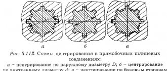
What determines the tension of the sling branches? At what angle between the branches are the slings designed?
The tension S of the branch of a single-leg sling is equal to the mass of the load Q (Fig. 3.13). tension S
in each branch of a multi-branch sling is calculated using the formula
where n
— number of sling branches;
cos b - cosine of the angle of inclination of the sling branch to the vertical.
Of course, the slinger should not determine the loads in the sling branches, but he must understand that as the angle between the branches increases, the tension in the sling branches increases. In Fig. Figure 3.14 shows the dependence of the tension of the branches of a two-legged sling on the angle between them. Remember, when you carry buckets of water, the load increases as you extend your arms. The tensile force in each branch of a two-leg sling will exceed the mass of the load if the angle between the branches exceeds 120°.
Obviously, with an increase in the angle between the branches, not only the tension of the branches and the probability of their rupture increases, but also the compressive component of the tension 5СГ (see Fig. 3.13), which can lead to the destruction of the load.
ATTENTION! Branch rope and chain slings are designed so that the angles between the branches do not exceed 90°. The design angle for textile slings is 120°.
What are the traverses used for? What traverse designs are used for slinging loads?
Traverses are removable load-handling devices designed for slinging long and large-sized cargo. They protect the loads being lifted from the compressive forces that arise when using slings.
According to their design, traverses are divided into planar and spatial.
Flat traverses (Fig. 3.15, a)
used for slinging long loads.
The main part of the traverse is beam 2,
or truss, which absorbs bending loads.
Rope or chain branches are suspended from the beam 1.
Crossbars with the ability to move the clips 4
along the beam are called universal
Fig. 3.15, b .
Equalizing blocks 5 are installed in the cages, which ensure uniform distribution of loads between the branches of the traverse
S1 = S2.
For this reason, such a traverse is called
a balanced one. Leveling blocks can also be used in rope sling designs with more than three branches.
Spatial traverses (Fig. 3.15, c)
used for slinging three-dimensional structures, machines, and equipment.
Different-armed balancing beam (Fig. 3.15, d)
used for lifting loads with two cranes, it allows you to distribute loads between the cranes in proportion to their lifting capacities.
Signs of a defective traverse:
Ø absence of stamp 3 or tag;
Ø cracks (usually occur in welds);
Ø deformation of beams, struts, frames with a deflection of more than 2 mm per 1 m of length;
Ø damage to fastening and connecting links.
What types of grips are there?
Grips are the most advanced and safe load-handling devices, the main advantage of which is the reduction of manual labor. Grippers are used in cases where it is necessary to move loads of the same type. Due to the wide variety of loads being handled, there are many different gripper designs available. Most of them can be classified into one of the following types.
Read also: U-shaped metal profile dimensions
Pincer grips (Fig. 3.16, a)
hold the load with levers
1
by its protruding parts.
Friction grips hold the load due to frictional forces. Lever friction grips (Fig. 3.16, 6)
clamp the load using levers 1.
Lever
have
with
blocks; they are used for slinging bales and bales.
In eccentric grips (Fig. 3.16, d)
The main part is the eccentric
4,
which, when turned, reliably clamps sheet materials.
Wedge (collet) grippers are designed for slinging loads with round holes.
The hooks are inserted under the load or into special holes on the load. These include forks (Fig. 3.16, d),
designed for slinging pallets.
Signs of gripper failure:
Ø absence of mark 2 or tag;
Ø blunting or chipping of the notch teeth on the working surfaces in contact with the load;
Ø bends and kinks of levers;
Ø wear of hinges.
There are also load-handling devices that provide automatic (without the participation of a slinger) slinging of the load.
two-branch 2 SC three-branch 3 SC four-branch 4 SC
Safety factor of chain and rope slings.
The safety factor is the ratio of the breaking force (in the certificate) to the load of an individual branch of the sling and must be at least 6 for steel slings, at least 7 for synthetic materials, at least 8 for natural fiber slings, and 4 for chain slings according to ISO (5 according to GOST).
The influence of the angle between the branches of the slings on the magnitude of the resulting force in them.
The greater the angle, the greater the load acting on the sling branch. The permissible angle is up to 90º, in some cases – up to 120º.
Rejection standards for SGP and containers.
Rejection standards are given in instructions No. 17 and 31
Auxiliary devices for convenience and acceleration of hooking loads.
Carbines, rocker arms, eye bolts, trunnions, clamps, eccentric clamps, pins, pliers, their structure and purpose. Rules for using them (selection, operation).
The procedure for manufacturing, testing, accounting, marking of slings, containers and auxiliary devices.
The sling is manufactured in the Mechanical Shop and in the Central Production Center. SGPs are inspected and tested only in the Mechanical Shop. The SGP is tested with a load exceeding the g/p by 25% and held for 10 minutes, and then a thorough inspection is carried out. Registration and marking are carried out in the Mechanical Shop and a certificate is issued, and for third-party organizations - a passport.
1. Manufacturer's name or trademark.
3. Serial number according to the manufacturer's numbering.
4. Test date and other information in accordance with the requirements of the technical specifications for a specific product.
| dк, mm | Number of punctures, not less |
| up to 14 | |
| 14 … 22 | |
| 22 … 28 | |
| more than 28 |
The sling loop is made by braiding the free end, clamping and crimping with an aluminum or steel sleeve.
Braiding of steel ropes is carried out by puncturing each strand of the rope. The number of punctures depends on the diameter of the rope. The last puncture is made with half the number of strands of rope, and the ends of the strands are wrapped with wire with a diameter of 1 mm. When braiding cotton, hemp and sisal ropes, the number of punctures is made at least 2 full and 2 half punches. The braided area should be wrapped with rope or protected in some other way.
For attaching the end of a rope to a ring, hook or other device
three devices for splicing two ends of the rope
Read also: Machine for knitting brooms
Various types of clamps are used: from two strips and two
bolts (Fig. a)
, U-shaped
(Fig. b)
and L-shaped
(Fig. c)
. Ma-
The material for the manufacture of clamps is steel grades St. 2 and Art. 3.
| dк, mm | Number of clamps |
| before 18 | |
| 18 … 28 | |
| more than 28 |
The minimum number of installed clamps must be at least 3, at a distance from each other of at least 6dk. The length of the free end of the rope is 6dk.
The certificate indicates the characteristics of the rope (chain), manufacturer, sling length, number of branches, diameter (caliber), design and breaking force. Rope slings can withstand dynamic loads better than chain slings.
The containers are manufactured at the Central Metallurgical Plant. After manufacturing, the container is inspected and tested in accordance with the requirements of the RD. Static tests
carry out a load exceeding the gross mass of the container by 10% and raise it to a height of 200 ... 300 mm, hold for 10 minutes. Static tests are repeated twice.
Dynamic tests
are carried out with a load exceeding the gross tare weight by 10% and raised to a height of at least 5 m, and while lowering to a height of no more than 1 m, braking is performed. Dynamic tests are carried out 5 times. Accounting and marking of containers must be applied to the CMC.
1. Manufacturer's name or trademark.
5. Date of manufacture.
6. Serial number after the manufacturer's numbering.
The safety factor is the ratio of the breaking load of the material used to make the rope to the design load of the rope.
The safety factor is determined by the formula: K,
where: K – safety factor;
F – breaking force of the rope, accepted according to the certificate;
S – rope tension
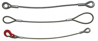
Slings. Purpose, classification
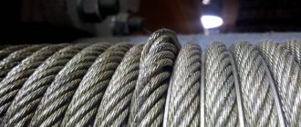
Slings are made from ropes, chains and textile tapes.
The production of slings from steel ropes and chains is regulated by the regulatory document RD 10-33-93 (as amended) “General purpose cargo slings. Requirements for the device and safe operation." The production of slings from textile tapes is carried out in accordance with RD 24-SZK-01-01 “General purpose cargo slings on a textile basis. Requirements for the device and safe operation."
Slings made from ropes of artificial and vegetable origin are manufactured according to developed technical documentation.
According to their design, slings are divided into branch and universal. Universal slings are designed for tying loads, and branch slings are designed for hooking them.
Universal rope slings are manufactured in two versions: USK1 – double-loop and USK2 – ring.
Branch rope slings, depending on the number of branches, have four designs: 1SK; 2SC; 3SK; 4SK.
Chain slings are manufactured in the following versions: USC-1; USC-2; 1SC – 4SC.
Textile-based cargo slings have the following designs:
branch sling STP; ring STC; branch loop with one metal link ST!1Z; branch loop with two metal links ST2Z; single-branch slinging device 1ST; two-branch slinging device 2ST; three-branch sling device 3ST; four-leg slinging device 4ST.
After manufacture, each lanyard must be subjected to a static load test of 25% greater than its rated load capacity.
During testing, the angle between the branches of general purpose slings is taken to be 90 º.
The sling is considered to have passed the test in the absence of residual deformations and cracks on the external surfaces of the sling elements, damage to the branches and loop fastenings. After testing, the sling is marked. The sling tag, made in the form of a plate or ring, indicates: the manufacturer's trademark, sling number, load capacity, test date.
Slings are tested only after manufacture. Slings cannot be repaired. Their rejection is carried out by visual inspection.
Read also: Indications on the pressure gauge
The designation of slings is indicated in the sling passport, which is issued by the manufacturer, and in the technical documentation.
1SK – 5.0/1800 – single-leg rope sling with a lifting capacity of 5 tons and a leg length of 1800 mm;
USK1 – 3.2/3000 – universal rope sling, version 1, lifting capacity 3.2 t, length 3000 mm.
Loading and unloading gondola cars
Loading (unloading) of gondola cars with hook cranes must be carried out using a specially developed technology (routine), taking into account the type of crane used and the nature of the cargo being moved. The technology must determine the location of slingers when moving loads, as well as the possibility of access to overpasses and overhead platforms. People are not allowed in gondola cars when lifting and lowering cargo. Loading and unloading of gondola cars must be carried out without disturbing their balance.
Examination card No. 10
Rules for transporting long cargo
When moving long cargo, it is necessary to use special guys, hooks and hooks for turning and guiding. Slinging should be done in at least two places, and the angle between the branches of the slings should be from 60 to 90 degrees. The correctness of slinging, lifting, and transportation is described in the technological maps. For slinging, the following are used: end grips, beam traverses, pincer grips, ring slings. The lifting is carried out in two steps.
Purpose of chain hoists
A pulley block is a system of movable and fixed blocks, enclosed by a flexible body (rope), which serves to gain strength (power pulley block) or speed (high-speed pulley block).
Power pulleys are used in cranes. Pulley hoists are characterized by multiplicity. Multiplicity is the ratio of the number of rope branches on which the load is suspended to the number of rope ends attached to the drum . Multiplicity characterizes the gain in strength.
Rejection of chain slings
if the brand (tag) is missing or damaged;
if there are no safety locks on the hooks;
in case of malfunctions of the end elements (presence of cracks, wear of the surface of the elements or local dents leading to a decrease in the cross-sectional area by more than 10%);
The following are not allowed on the flexible chain element of a chain sling:
cracks in chain links;
elongation of a chain link by 3% or more of the original size; reduction in the cross-sectional diameter of a chain link due to wear of more than 10%.
Tara. Marking, rejection
To move bulk and small-piece cargo, liquid, viscous materials, special containers and packaging means called containers are used.
The manufacture of containers must be carried out according to technological maps or individual drawings. After manufacturing, the container is subjected to technical certification by inspection. The container must be marked, but which indicates the serial number of the container, its own weight, carrying capacity and purpose.
During operation, the container is inspected by the slinger before its use and periodically every month by the official who is assigned this responsibility by order of the organization.
The inspection is carried out according to instructions developed by a specialized organization.
in the absence or violation of markings;
in the presence of significant deformations;
if there are cracks in welds or base metal;
if hinges or other hooking devices are damaged;
in case of malfunction of locking or fixing devices;
when the lugs are worn by 10% or more of the original diameter.
The container must have a fill line marked on it. On containers intended for transportation of bulk and small-piece cargo, a line is drawn at a distance of 100 mm from the level of the sides; on containers for liquid materials and mastics, a line indicates ¾ of the volume of this container.
Unmarked, faulty and not technically certified containers should not be located in work areas