Plate Conveyor
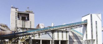
A plate conveyor is a device that transports goods during production and performs these actions continuously. This device is used when moving various cargoes between sectors of ongoing work operations, during the production of various technological operations and in the event that it is impossible to use a conveyor belt device.
Plate Conveyor Design
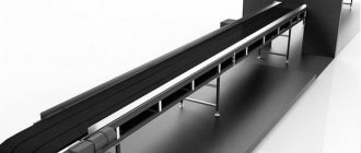
The apron conveyor consists of the following structural components: flooring, traction chains, drive station, metal structure and tension station. The flooring is made up of individual plates, and a similar element of the device is attached to the traction chains. The structure of the drive station includes an electric motor, a gearbox and various couplings. The metal structure contains load-bearing elements for holding chains. Also, the plate conveyor can be equipped with loading and unloading devices, control and measuring instruments.
The functional and working (route) movements of these conveyors are divided into horizontal, inclined and horizontally inclined. For inclined movements the angle is 35-45°. Routes like those of a conveyor belt. The bending of a plate conveyor is possible in a horizontal surface with a radius of 3-10 m. The rate of movement of the undercarriage of this conveyor is determined by its efficiency and the characteristics of the transported cargo. It is equal to from 0.01 to 1 m/s. As a rule, the speed of the chassis is set to 0.05-0.2 m/s.
The driving components of apron conveyors are a pair of traction flail devices. The pitch of the traction flail elements varies from 63 to 800 mm. These chains exist in several varieties: bushing, roller, roller with smooth rollers, roller with flanges on rollers. Any of these flail mechanisms are produced in three versions: non-separable - index M, collapsible - index M and non-separable with hollow rollers - index MC. The use of rollerless flail components necessitates the installation of rollers to the chain links, every 400-800 mm. Such rollers are easy to maintain and repair. To lubricate such devices there is no need to dismantle them.
The rollers of the apron conveyor are the supporting elements. With their help, the force of gravity from the flooring and the load that moves is supplied to the supporting paths of the apron conveyor. Rollers exist with and without sides. These devices can also be made from metal raw materials or plastic elements.
The deck of an apron conveyor is the part of the equipment that bears the heaviest load. Therefore, depending on the load being moved, the flooring may have a different design. For example, in light industry the following types of flooring are most often used: flat open, flat closed and side wavy. Flat decks are made from wood, steel and other materials. The main parameters of the flooring are its width B and the level of the sides, if any.
In the design of the apron conveyor, two types of tensioning devices are used: screw and spring-screw. The stepwise movement of the slider in the tensioning device depends on the pitch of the traction chain that is used. One tensioner sprocket is inserted onto the shaft mechanism (on a key). The other sprocket is left free, to allow self-installation, at the location of the hinge joints of the chain. The end parts are made in the form of a tension device drive. The middle part for the base of the deck is made in the form of special metal parts 4-6 m long. Angles or pipes are used as carriers for the traction chain rollers.
Plate conveyor: device, types, principle of operation
Conveyors are often used to transport various products. There are quite a large number of different versions of such equipment; plate-type ones are common. Similar continuous action mechanisms are used in a wide variety of production sites.
Scope and device
On production lines and in other conditions, a plate conveyor is installed. The design of the chain conveyor for apron conveyors, the design of the entire equipment determines the following scope of application:
- Movement of material represented by pieces of various origins.
- Transportation of heavy piece goods.
- At the time of transportation, materials can also be subject to various types of processing. That is why conveyor-type mechanisms are very widespread today, since multi-stage processing is carried out to increase productivity.
- Bulk and other materials can be transported in horizontal and inclined directions.
- The mechanism is found in a wide variety of production facilities. Examples include chemical, mining, energy and some other industries.
The operating principle of a plate conveyor allows them to be used for moving various bulk and bulk cargoes and abrasives. Closed loop systems have become quite widespread. Conveyors are most often used in the metallurgical industry and are installed to transport ore of various sizes. In the mechanical engineering field, hot castings, forgings, stampings and many other workpieces are often transported.
There are also special versions that are used for transporting certain goods. Some of them are related to stream redirection and many other tasks.
Types of apron conveyors
A wide variety of apron conveyor types are available. In most cases, a chain drive is installed, which is characterized by increased strength. The main types of mechanisms can be called:
- The horizontal plate conveyor has become quite widespread. Its task is to transport various materials, as well as parts at the time of their stage-by-stage processing. The key feature is the large length of the device.
- In some cases, an inclined horizontal plate conveyor is installed. Its purpose is not only to transport cargo, but also to lift it.
In addition, classification is carried out according to the type of material used in manufacturing. Recently, stainless alloys, which can last for a long period, have become widespread.
Classification is carried out according to the recommended area of application. It looks like this:
- Transportation of round loads.
- Moving piece goods.
- Transportation of bulk cargo.
The type of plates installed and many other operational characteristics largely depend on the place where the device is used.
Chassis of apron conveyor
The design consists of a fairly large number of different units, one of them is the chassis. It consists of several main elements:
- Flooring.
- Bracket.
- Rigid reinforced links.
The type of flooring is selected depending on the type of transported raw materials. Another important parameter is the angle of inclination. The choice is made depending on GOST 2035-54. The main dimensions of the flooring can be called length and width, which largely depend on the installation location.
A variety of materials can be used in the manufacture of plates. In most cases, steel is used, but the flooring can be made of wood or plastic planks.
Steel plates are made from sheets whose thickness is 1-3 mm. Fastening is carried out using welding technology.
Inclined plate conveyors have transverse stiffeners, which prevent the transported load from rolling down.
Plate sizes
The plates are also classified according to their sizes. They vary over a fairly wide range. Among the features we note the following points:
- Bulk cargo is placed in the form of a triangle in the case of using a canvas without sides. Stability is achieved by significantly increasing the rigidity of the base.
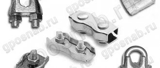
- Chains of various designs can be used as a traction element. Their common property is increased strength. At the same time, the chains are characterized by ease of installation and low pre-tension. The most widespread are bushing and roller versions of chains; they are considered a universal offer. There are other versions that have their own specific properties.
The size of the plates is important for inclined installations and many other applications.
Tension stations
The plates are transported by a chain. In this case, the connection is carried out using special parts.
The tensioning station consists of the following elements:
- Frames.
- Vala.
- Drive sprocket.
- Bearing.
The force is transmitted through gearing. The operating principle is as follows:
- Rotation is created by an electric motor. It is characterized by a fairly large number of different features, for example, power and number of revolutions.
- A gearbox is installed as an intermediate element. It reduces the number of revolutions and significantly increases traction. In some cases, an additional belt or chain drive is installed. The belt eliminates the possibility of exceeding the permissible threshold of the transmitted force.
- When setting up the tensioning station, care is taken to ensure that the chain passes with the least tension at the bend points. This moment allows you to reduce the degree of wear of the product.
- If the route is characterized by high complexity, then the installation location of the drive is selected in accordance with the calculations performed.
- The excessive length of the apron conveyor route means that it is almost impossible to avoid strong chain tension. That is why several motors are installed, which eliminate the possibility of product rupture.
In most cases, on industrial apron conveyors, the drive is installed in the head part of the structure. In this case, smooth speed control is carried out by installing a special variator. Reverse movement of the plates is eliminated by installing a special brake.
Calculation of apron conveyor
When replacing major components and performing maintenance, a variety of parameters must be taken into account. Belt conveyors are driven by an electric motor. The blade is replaced only taking into account the minimum tension, which is taken on the running branch.
In addition, sprockets are installed on rotary and inclined sections. The tension is calculated at the time of design.
Advantages and disadvantages
For a long period, exclusively tape versions were used. Plate devices are characterized by a fairly large number of advantages and disadvantages. The advantages include the following:
- High degree of adaptability to transporting hot, sharp-edged, large-piece and other loads that can cause surface damage. This moment determined the widespread use of the device in industry and many other areas. The metal sectional tape withstands environmental influences; when soil or other loose soil falls, no defects appear on the surface.
- The use of metal makes it possible to transport cargo at high and low temperatures. It was this moment that made it possible to use conveyors for transporting hot workpieces in mechanical engineering and other industries.
- Design features make it possible to create inclined and other types of apron conveyors. Horizontal devices are widely used, but inclined ones can also be installed, which allow lifting the load to a certain height.
- A high degree of productivity is also one of the main advantages of the apron conveyor. It is achieved by installing an electric motor, gearbox and some other mechanisms.
- It is possible to use decking with special fastening elements for transporting various loads. Examples include sides and cross plates.
- You can load directly from the hopper, which increases efficiency.
There are several significant disadvantages that must also be taken into account. An example is the following:
- The use of metal in the production of basic elements determines that the weight of the structure increases significantly. That is why it is necessary to install the mechanism on a special base, which will be designed for high loads. In addition, attention is paid to fixing the base.
- Another important point is the complexity of manufacturing. This also determines that the maintenance procedure requires significant financial investments. Some parts cannot be found on sale; they are made to order.
- The high cost of the chassis is also associated with the use of metal and other similar materials in the manufacture of the structure. That is why installation is carried out in cases where higher performance characteristics are required.
- Low transportation speed. This property can simultaneously be called an advantage and a disadvantage, since the efficiency indicator is significantly reduced. The movement speed is reduced by reducing the number of revolutions, for which a gearbox is installed. It can reduce the number of revolutions several times.
- Complicated operation due to the installation of a large number of articulated joints. Such structural elements are characterized by relatively high complexity. Excessive load and operation without proper maintenance can lead to serious defects.
- The device requires constant care and monitoring, since minor defects over a long period can cause the entire device to fail. In addition, periodic checking of the degree of chain tension, which is responsible for transmitting force, is carried out.
- High difficulty in replacing rollers and other elements. That is why maintenance should be carried out exclusively by a specialist who knows all the features of the device.
- Due to the large mass of the main elements, significant resistance to movement arises. This is why there is a significant load on the electric motor and the intermediate element.
When choosing an apron conveyor, you should pay attention to all the advantages and disadvantages. This is due to the fact that in some cases it is better to install a strip structure. In addition, the design for transportation is characterized by a huge number of different characteristics.
Features and Benefits
Before choosing a particular screw conveyor model, it is worth analyzing its operating parameters, which are directly related to the efficiency of the unit.
- Screw direction. The plane in which the raw materials will move must best meet the requirements of the production process. The direction can be horizontal or vertical.
- Frame. It may take the form of a gutter or a closed pipe. In many ways, the ability of the device to deliver materials to the required height depends on this detail.
- Length. It can be very small (just a few meters), or it can reach 40 m.
- Performance. Its indicator depends not only on the power of a particular model, but also on the material that you intend to move.
- Mechanism. The design of the device can be either stationary or mobile. In the second case, the conveyor is installed on a wheelbase. This allows you to move it around the workshop or transport it to the place where raw materials are loaded.
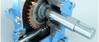
Elevators
An elevator is a transporting device that moves material in a vertical direction (Fig. 16.14). The elevator consists of a head 1, a shoe 5 and a sealed casing 3. The traction element of the elevator is a conveyor belt 2 with a width of 250-600 mm or (less often) a chain. The belt goes around the upper drive drum and the lower tension drum. Buckets 4 are installed on the belt. The material is loaded into the elevator through a loading funnel. When the buckets go around the lower drum, they scoop up material, lift it up and unload it on the upper drum.
The elevator drive is equipped with a device that prevents reverse movement of the belt. For wet materials such as sand; shallow ladles are used (Fig. 16.15, a), and for dry materials (sand, ground clay) - deep ladles (Fig. 16.15, b).
Elevators work well when transporting dry bulk materials. Wet materials stick to the buckets during transportation, resulting in loss of productivity. When transporting waste mixtures, elevators also operate unreliably, since metal inclusions get in with the mixture, which leads to damage or breakage of the belt. When designing modern foundries, they tend not to use elevators to move the initial molding materials and mixtures, and instead, if possible, install inclined belt conveyors.
The speed of movement of the elevator belt for powdery goods is 2-2.5 m/s, and for lumpy goods 1-2 m/s.
Main characteristics of scraper conveyor
The scrapers themselves, as a rule, are made of cast steel, the chute is also most often made of metal, but there are also wooden models.
The great advantage of scraper conveyors is that they can be unloaded and loaded at any part of the chute, which in some cases is convenient and even necessary. The speed of this type of conveyor can reach one meter per second, and the productivity can vary from fifty to three hundred and fifty tons per hour of operation, it depends on the model and use of the conveyor. As a rule, such conveyors are used to move goods over a distance of up to one hundred meters.
The design of a scraper conveyor includes such necessary working elements as a stand, a chain mechanism, the scrapers themselves, chutes, a station that drives all equipment, and an end-type head. This equipment can also be classified into the following types and types. Today, conveyors that carry out underground work are widely used, for example in mines and mines; conveyors for general purposes are also common, that is, for use in processing plants and on the surface of a mine. There are also special purpose conveyors, such as those used in mining and transport type machines.
Scraper conveyors also differ according to the type of their drive. There are and most often used in enterprises are conveyors with an electric drive type. Also, quite often, far from the electrical network, pneumatic conveyors of this type are used. And finally, there are also hydraulically driven scraper conveyors, which are also quite common in various work areas.
Vibrating Conveyors
Unlike oscillating conveyors, in which the load slides along the chute without leaving it, vibrating conveyors (Fig. 16.18) operate with accelerations whose vertical component is greater than the acceleration of gravity. In this case, a particle of cargo breaks away from the chute and moves in the form of microflights continuously following one after another. With this movement, the load does not crush, does not generate dust and practically does not wear out the chute. The most efficient transportation of bulk cargo will be if, at the end of the microflight, the particle hits the chute at the beginning of the next period of oscillation. The trough or pipe of a vibrating conveyor is usually mounted on spring suspensions. The oscillation frequency of the vibration conveyor up to 50 Hz with an amplitude of less than 1 mm is created by inertial, electromagnetic, pneumatic and hydraulic vibrators.
Inertial vibrators are used in cases where, with small overall dimensions and mass of the drive, it is necessary to obtain significant disturbing forces. An inertial vibrator includes a vibrator with an unbalanced electric motor (Fig. 16.19, a).
Most of the designs of these types of vibrators are designed for one constant operating frequency, but there are vibrators with adjustable frequency. The disturbing force can also be adjusted. Due to the lower oscillation frequency (15-25 Hz), feeders with an unbalanced electric motor operate less noisily.
The most advanced are electromagnetic vibrators (Fig. 16.19, b). They do not have rubbing or wearing parts, and it is possible to regulate the amplitude of vibrations without stopping the operation of the installation.
The force P created by the electromagnetic vibrator can be determined by the formula:
P = maω2(λ – 1),
where m is the mass of the material being moved, kg; a – vibration amplitude, m; λ – the ratio of the natural frequency of vibration of the conveyor together with the material ω0 to the frequency of vibration of the drive (forced frequency) ω; λ = ω0/ω.
The main advantages of vibrating conveyors: the ability to transport cargo in conditions of complete isolation from the environment in closed gutters or pipes; the ability to perform other technological operations simultaneously with transportation - drying, cooling, mixing, sifting, etc.; low wear of the supporting element (pipe or gutter); comparative simplicity of the machine design; possibility of intermediate loading and unloading; low energy consumption during steady operation.
Along with horizontal vibrating conveyors in foundries, vertical conveyors are increasingly used to move goods along a vibrating chute 2 running upward along a helical line (Fig. 16.20). To do this, the chute, mounted on springs 3, is given a reciprocating rotational movement around a vertical axis and an oscillatory movement along the same axis using vibrators 1. The material moves in the same way as in a horizontal chute, through microflights, but during vertical transportation these flights are performed not in a straight line, but along a continuously changing tangent. The maximum height of vertical vibrating conveyors reaches 8 m; the ratio of the height to the outer diameter of the screw chute can reach up to 10. Small-piece and granular cargoes (coke, slag, ore, sand, clay) are transported at the highest speed; at a lower speed - dusty loads (ground clay, asbestos chips, ground coal, marshalite). When moving wet, non-sticky loads (such as wet sand), a more stable flow is created. When humidity is more than 12%, the speed of movement decreases sharply. Wet, sticky materials (such as wet clay) should not be transported on vibrating conveyors. The speed of movement of goods by horizontal vibrating conveyors is in the range of 0.1-0.3 m/s.
The angle of inclination of the trough of vertical vibrating conveyors usually does not exceed 15-20°.
Vibrating conveyors are significantly (3-4 times) more economical than belt conveyors, and vibrating feeders are more economical and lighter than belt, swinging and disc feeders. However, when transporting over a distance of more than 50 m, vibrating conveyors are inferior to belt conveyors both in terms of metal consumption and energy consumption. Vertical conveyors are used only in workshops where there is no space to accommodate belt conveyors, and the lifting height of dry bulk materials is relatively small (30-40 m).
Methodology for calculating key indicators
To produce screw conveyors, it is necessary to perform a large amount of design and technological preparation. It includes the production of product drawings, the construction of its kinematic diagram, and engineering calculations.
To calculate a screw conveyor, it is necessary to take into account the main parameters. These include:
- Spiral pitch t. depends on the specific gravity ρ of the transported substance; with increasing density, the step must be reduced.
- Shaft rotation speed n. For light loads, the speed reaches 120 rpm; for dense and viscous loads, the speed must be reduced to 30 rpm.
- Screw diameter d. also decreases with increasing specific gravity and viscosity.
- The gutter filling rate ψ, depending on the density of the material, ranges from 15 to 40%.
- C - correction for the elevation angle, for horizontal devices C = 1, for vertical screw conveyors the value is taken from the tables;
The performance of the screw mechanism is calculated using the formula:
Engine power sufficient for reliable operation of the conveyor with a given performance is determined by:
- mass of the shaft with blades;
- weight of the load in the pipe;
- linear speed of movement;
- a number of correction factors for friction.
Finally, the power is determined taking into account the efficiency of the gearbox and adding the standard power reserve required to start a conveyor filled with cargo.
Oscillating Conveyors
An oscillating conveyor is a chute suspended on a stationary frame. The chute makes oscillatory movements, as a result of which the load located in it moves.
Oscillating conveyors can have variable or constant load pressure on the chute. An oscillating conveyor with variable load pressure on the chute (Fig. 16.17, a) consists of a steel chute 1, which performs oscillatory movements on elastic posts 2 under the action of a crank mechanism 3. Due to the fact that the support posts are installed obliquely to the chute, the latter carries a load when moving It rises slightly forward and lowers when moving backward. The length of the crank is chosen to be small compared to the length of the connecting rod and the length of the support legs, as a result of which the law of change in the speed of the chute vm is close to sinusoidal, and the movement of the chute itself can be considered as rectilinear.
The vibration amplitude of conveyors with a crank mechanism is 30-40 mm with a number of cycles of 300-400 per minute. The elastic support posts of the chute are installed with an inclination at an angle α = 2÷30° relative to the vertical in the direction opposite to the movement of the load. The average speed of movement of the load v is usually 0.15-0.20 m/s. For inclined conveyors, with an increase in the angle of inclination of the chute towards the lift, the speed of movement of the load decreases sharply and the angle of inclination does not exceed 15°.
Oscillating conveyors with constant load pressure on the chute differ from conveyors with variable pressure in that the chute in them is installed on roller or ball bearings and it performs a longitudinal translational-return movement under the influence of a double crank mechanism (Fig. 16.17, b). This mechanism consists of an articulated four-link OABC, in which the crank OA rotates uniformly, and the crank BC, which rotates unevenly, transmits oscillatory motion to chute 1 through rod 2. The height of the material layer in chute b is taken to be 50-100 mm; The gutter fill factor is usually 0.5-0.6. The average speed of movement of cargo in a horizontal chute is taken to be no higher than 0.2 m/s. The amplitude of the gutter vibrations is 50-100 mm, and the frequency is 1-2 Hz.
Application area
Scraper-type conveyors have found very wide application in a wide variety of economic fields.
These are grain processing enterprises, mills, above-silo and under-silage galleries of elevators, feed mills, cereal and oil extraction plants, enterprises processing oilseeds and grain.
In addition, this equipment is used in reception departments of railway and road transport and other enterprises that work with bulk materials that are similar in their physical and mechanical properties to grain.
In short, scraper conveyors are in demand in many areas of both agricultural and industrial production.
Trackless transport vehicles
Trackless transport vehicles in foundries include electric vehicles, trucks and forklifts.
Electric cars and forklifts are the most common type of trackless intra-shop transport in modern foundries, especially mass production.
An electric car (Fig. 16.27) is driven by one or more DC electric motors powered by batteries. Batteries are the most critical part of an electric car; they are usually installed next to the driver’s seat. The electric car is easy to maintain and operate, maneuverable, and fire-safe. During its operation, no exhaust gases are emitted, it does not produce noise when moving, starting and stopping indoors.
An electric car usually has lifting platforms and cargo stands, so loading and unloading does not require the use of physical force. Charging stations are specially equipped to charge the batteries of electric cars. For safety reasons, the braking system of the electric vehicle's chassis is designed in such a way that when the driver's foot is removed from the control platform, the electric vehicle instantly stops and is de-energized. Cars in appearance are almost no different from electric cars. Instead of an electric motor and batteries, the car has a conventional gasoline engine.
Automobiles do the same job on the shop floor as electric vehicles, but are less common. This is explained primarily by the fact that they create noise during operation, are more difficult to operate and maintain, and exhaust gases pollute the atmosphere of the workshop. Forklifts are used for loading and transporting large-sized cargo both within the workshop and for inter-shop transportation.
The forklift is mounted on a chassis, but the distance between its front and rear wheels is much less than that of conventional cars, which makes it very maneuverable. Instead of a body, the forklift is equipped with two vertical columns-guides for moving along them a traction chain with forks or a special platform for capturing, lifting and transporting loads.
Plate sizes
The plates are also classified according to their dimensions. They vary over a fairly wide range. Among the properties we note the following points:
Bulk cargo is located in the form of a triangle in the case of using a canvas without sides
Durability is achieved through an important increase in the rigidity of the base. Chains of quite different designs can be used as a traction element. Their identical property is very high strength
At the same time, the chains are distinguished by the ease of installation and low pre-tension. The most widely used are bushing and roller versions of chains; they are a multifunctional offer. There are other implementation options that have their own characteristics.
The size of the plates has priority in inclined installations and in most cases.
Overhead conveyors
Overhead conveyors are used for continuous or periodic transportation of various piece goods. For example, after beating, hot castings are transported in containers on an overhead conveyor to the heat-shearing department. After production, the rods are transported by machine for subsequent painting, drying and storage. Overhead conveyors are used in the casting cleaning and finishing departments.
The overhead conveyor (Fig. 16.11) consists of a closed traction element 3 with carriages 2, which serve to support the traction element and secure suspensions 4. The rollers of the carriages with the help of the traction element move along a closed suspended path 1. Chains of all types are used as a traction element (plate , welded, cast, etc.), as well as steel ropes. Sometimes chains are double-hinged, the axes of which are located in two perpendicular planes, which provides greater flexibility of the chain in all directions. The route of an overhead conveyor can be horizontally closed or have a complex profile with ascents, descents and turns. These conveyors are simple and reliable in operation.
Overhead conveyors (Fig. 16.12, a, b) can be load-carrying, in which carriages with load hangers are permanently connected to the chain, and pushers, in which carriages with load hangers do not have a permanent connection with the chain and move with the help of cams attached to chains. The chain with carriages and cams moves along an auxiliary overhead track, and the trolleys with loads move along the main cargo track.
In overhead push conveyors, which are the most easily automated (Fig. 16.13), push carriages 1, connected to a traction chain 4, move along a rail track 3 on rollers 2. Cargo trolleys 5, not connected to a traction chain 4, move along the lower suspended track b, located under the auxiliary. On the traction chain (and in other designs - on the load carriages) there are swinging thrust levers 7, which rest on the load cart 5 (or on the protrusion on the traction chain) and move it in a given direction.
The cargo carts are not directly connected to the traction chain, therefore, having transfer arrows along the path of movement of the cargo carts, it is possible to manually or automatically remove the cargo carts from the main path to the processing line and then return them to the main route for further movement. This makes it possible to combine individual, even different in rhythm, transport and technological operations into one fully automated system.
Overhead push conveyors perform the following operations: transfer trolleys with loads from one conveyor to another using automatic or remotely controlled switches; automatically distribute cargo among warehouse racks while simultaneously sorting them; issue cargo from warehouses in the required rhythm according to a given program.
At a number of factories, overhead push conveyors perform all of the listed operations related to the production of cores, their finishing, painting, drying, transportation to a warehouse, targeted storage, delivery from a warehouse according to a given program to automatic molding and filling lines.
One of the important advantages of overhead push conveyors is the ability to automatically count transported products for each item, regardless of their quantity. Accounting can be either in pieces or by weight. In recent years, improved systems of overhead push conveyors with automatic control and load addressing have been widely used, making it possible to mechanize labor-intensive work.
Disadvantages of push conveyors: greater overall height than a conventional load-carrying overhead conveyor, higher dead weight of the structure per unit length of track, and relatively high cost.
, an OEM/ODM custom conveyor manufacturing company
A total of 144 apron conveyor factories and companies with 432 products were found. Order high quality apron conveyors from our huge range of reliable apron conveyor factories. Golden member
| Business type: | Manufacturer / Factory |
| Main products: | Roller Chain, Conveyor Chain Chain, Welded Chain Link, Forged Parts, Sprocket/Gear/Bush |
| Mgmt.Certification: | ISO 9001 |
| Location: | Suzhou, Jiangsu |
Diamond cock
| Business type: | Manufacturer/Factory, Trading Company |
| Main products: | Modular belt, top chain, stainless steel mesh belt, stainless steel chain, flexible chain |
| Mgmt.Certification: | ISO 9001 |
| Factory property: | Limited Liability Company |
| R&D volume: | OEM,ODM,own brand |
| Location: | Shanghai, Shanghai |
Golden member
| Business type: | Manufacturer/Factory, Trading Company |
| Main products: | Belt Conveyor, Chain Conveyor, Plastic Chain, Stainless Steel Chain, Modular Belt |
| Mgmt.Certification: | ISO 9001, ISO 20000 |
| Factory property: | Limited Liability Company |
| R&D volume: | OEM,ODM |
| Location: | Shanghai, Shanghai |
Diamond cock
| Business type: | Trade company |
| Main products: | Belt Conveyor, Roller Conveyor, Chain Plate Conveyor, Screw Conveyor, Bucket Elevator |
| Factory property: | Limited Liability Company |
| Location: | Zhengzhou, Henan |
Diamond cock
| Business type: | Manufacturer/Factory, Trading Company |
| Main products: | Mixer, packing machine |
| Factory property: | Limited Liability Company |
| R&D volume: | ODM, OEM |
| Location: | Shanghai, Shanghai |
| Production lines: | 5 |
Diamond cock
| Business type: | Manufacturer / Factory |
| Main products: | Paper Making Machine, Paper Punching Equipment, Paper Making Machine Spare Parts |
| Mgmt.Certification: | ISO 9001, ISO 22000 |
| Factory property: | Limited Liability Company |
| R&D volume: | OEM |
| Location: | Jiaozuo, Henan |
Diamond cock
| Business type: | Trade company |
| Main products: | Roller Conveyor, Belt Conveyor, Food Processing Line, Fruit Washing Machine, Brick Making Machine |
| Mgmt.Certification: | ISO 9001, IATF16949 |
| Factory property: | Limited Liability Company |
| R&D volume: | OEM, own brand |
| Location: | Dezhou, Shandong |
.Conveyor
Floor-rail intra-shop transport
To move heavy loads between bays over short distances, many foundries use self-propelled floor-rail trolleys, which can be non-driven or driven. Non-powered trolleys are moved along the rails using a special winch and ropes. The traction winch with a drum for winding the rope is usually located in a pit below the floor level. In a drive (self-propelled) trolley with an electromechanical drive, the electric motor with gearbox is located on the trolley itself, and power is supplied to the electric motor via a special cable or through trolleys built into the pit between the rails. The pit is usually closed with removable plates, and only a narrow gap is left for the current collector. The track of self-propelled trolleys is usually 1524 or 750 mm.
In new workshops, they try to avoid the use of rail transport, since it is less convenient than trackless.
Main varieties
Plate conveyors have become widespread. In most cases, the following types of conveyors are used in production:
- Horizontal. The task is to move a variety of materials and parts during the process of step-by-step processing. The peculiarity is the large length of the device.
- Rotary-horizontal. The purpose is not just to move products, but also to change the trajectory of movement.
But classification of devices is also possible according to the type of material used in manufacturing. Thus, recently, conveyors made of stainless alloys, characterized by a high service life and immunity to rust, have become especially popular. The deck of an apron conveyor is the part of the equipment that bears the greatest load, so there are divisions based on its type.
Screw conveyors
A screw conveyor is a device used to move material along a chute using a rotating screw (Fig. 16.21). It consists of a stationary chute 7, closed on top by a lid 3, a drive shaft 8 with turns of the transport screw mounted on it, end 2, 6 and intermediate 4 supports, drive 1, loading 5 and unloading 9 devices. When the screw rotates, the load moves through the turns of the screw along the chute.
Screw conveyors are used to transport dust-producing materials (ground clay, marshalite, etc.); At the same time, tightness is easily ensured. A screw conveyor can transport materials not only horizontally, but also along inclined and vertical chutes. These conveyors are not suitable for moving bulky, abrasive or sticky loads.
The pitch of the screw is usually equal to its diameter or slightly less. The screw rotation speed depends on the density of the material: for heavy materials n = 0.8 s-1, and for light materials 1.5 ÷ 2.5 s-1.
Advantages and disadvantages of chain conveyors
Like any mechanical equipment, chain material handlers have strengths and weaknesses. Depending on the given technological process, it is necessary to select what is needed in a given situation. Advantages of chain conveyors:
- high performance;
- wide power range;
- sealed housing, which prevents spillage of cargo;
- lined steel body and work surface.
Disadvantages of chain material handlers:
- massive and dimensional design;
- many parts and components subject to wear due to friction processes;
- difficulties in maintenance and repair work;
- increased noise level during operation.
Pneumatic transport systems
Pneumatic transportation is the movement of goods through pipes due to air pressure differences. Mixed with air, they transport mainly powdery and granular materials (clay, coal, sand, sawdust, etc.), less often dry sand and molding mixtures over a distance of up to 2 km and to a height of up to 100 m.
Pneumatic transport units are divided into suction, discharge and combined.
The operating principle of suction units is based on creating a vacuum of air in the transport pipeline (Fig. 16.22, a). Suction units are low-performance, since it is difficult to create a large vacuum (more than 10 kPa). Typically, in foundries, suction pneumatic units operate at a vacuum of no more than 10 kPa to transport dusty materials over short distances. The advantages of suction-type installations are that the material can be taken from different places, and in addition, in the event of a leak in the pipeline, dust will not be released into the workshop.
Injection units operate under the influence of compressed air supplied to the transport pipeline (Fig. 16.22, b). These installations are used for transporting heavy dusty and lumpy cargo over long distances. The disadvantage of injection units is the release of dust into the workshop when the tightness of the pipelines is broken, and increased wear of pipelines in the elbows.
To create the required air pressure difference in the pipeline, compressors and blowers are used in injection units, and vacuum pumps and high-pressure fans are used in suction systems. Screw and chamber feeders are used as feeders in pneumatic conveying systems.
Screw feeder (Fig. 16.23) is a short screw (screw) conveyor mounted on frame 1. The feeder screw 4 has a variable pitch, which allows the transported material to be compacted during operation so that the corresponding compressed air pressure is constantly maintained in the transport pipeline 8. Transported material from the loading funnel 3 is fed by screw 4 into the mixing chamber b. The degree of compaction of the material is regulated by a load valve 5. In the lower part of the mixing chamber there are two rows of nozzles 7, through which compressed air is introduced. The air aerates the material and introduces it into the transport pipeline 8. The advantage of screw feeders is their small overall dimensions and ease of operation, the disadvantage is the high power consumption of the electric motor 2 and rapid wear. A chamber feeder (Fig. 16.24, a, b) is a cylindrical vessel with a spherical upper and conical lower bottom with an upper or lower outlet of material. Loading occurs through the upper neck of a large cross-section with a conical lid that is hermetically sealed from the inside. Compressed air, coming from the compressor and passing through the material in the chamber, tends to escape through the transport pipeline and carries the material with it.
A feeder with top dispensing of material provides better loosening of the material, which contributes to more efficient transportation.
To protect pipeline elbows from wear, special protective devices are used, one of which is shown in Fig. 16.25.
Injection units are used not only for moving bulk materials, but also for transporting piece goods (delivery of steel samples, molding sand and other materials to an express laboratory for analysis). The load is placed in special cartridges, which move at a speed of 6-10 m/s in pipelines under compressed air pressure.
A type of pneumatic transport are air chutes used for transporting sand, ground coal, ground clay, marshalite and other powdery materials over short distances (up to 50 m). The air chute (Fig. 16.26) for transporting and cooling sand is an inclined trough 9 with a door 10 for inspection and with a horizontal perforated canvas 5, on which the sand flowing through the tray 7 moves. Air under a pressure of 2.5-3.0 kPa is pumped fan 8 under the canvas and in the form of tiny streams passes through the sand and brings it into suspension. Due to the inclination of the gutter and the movement of the ventilation air flow, the air mixture (a mixture of air and material) also comes into motion. In the upper part of the gutter, in addition to ventilation pipelines 5, 6, there is a sand trap 4. Cooled sand flows through tray 2 into hopper 1.
The advantages of pneumatic transport are the ability to transport along a complex route and locate pipelines in any direction; combining the transportation of material with technological operations (drying, cooling, selection of fine fractions, etc.); almost complete automation of transportation. Disadvantages – high energy consumption; increased wear of pipelines; the need to thoroughly clean the exhaust air from dust before releasing it into the atmosphere; impossibility of transporting wet and sticky loads (ready-made molding sand); increased crushing of the transported material (molding sand).
Suction pneumatic installations are most widely used in foundries. Recently, there has been a tendency towards a wider use of low-pressure injection pneumatic conveying units, and therefore low speeds of material movement. This reduces the wear of pipelines and increases the reliability of the entire system. In order to maintain constant air pressure along the entire route, they resort to intermediate air supply into the transport pipeline.
Operating principle of chain conveyors
In production and enterprises of various profiles, the use of chain conveyors in technological lines and processes has become quite common. Such loaders are designed to move bulky and voluminous cargo, for substances that have a high temperature range.
The productivity of this type of conveyors is very high compared to belt analogues. Although they usually have significant overall dimensions, chain material handlers are capable of performing the work assigned to them at a very high technical level. Consequently, despite their high cost and the troublesome maintenance they require, chain type material handlers have proven to be stable operating and wear-resistant mechanical equipment. Chain units are most widely used in the automotive and engineering industries, where components and spare parts for various mechanisms are supplied using conveyors of this type.
The operating principle of these machines is that torque is supplied to the actuators through chains. Depending on the engineering plans, there may be one or two such components of a chain loader. Conveyors are designed in such a way that it is possible to load, transport, on two branches at once and then unload the transported substance. Chain units have a box design, in the body of which there is a partition. Chain material handlers are designed from standardized units to simplify repairs and maintenance. The conveyor is designed with three sections: wire section, tension section and intermediate section. The driving element of such a loader is a chain https://privod-tsepi.ru/, equipped with special scrapers.
The chain, depending on the technical requirements and operating conditions of the equipment, can be forged or have a round link design.
During operation of this unit, the scraper chain is immersed in a layer of substance that fills the entire working space of the box. The product is picked up by the lower branch of the chains and transported along with them continuously.
Next, the transported cargo is fed into the conveyor through a loading hole built into the cover of the intermediate compartment, and is transported by a chain along the bottom to the final unloading point.
The final unloading of the substance is carried out from the unloading funnel, which is installed in the drive compartment.
Trolley conveyors
Trolley casting conveyors serve as the main transport device for flow-mechanized and automatic molding and knocking lines (Fig. 16.5). According to the nature of the route, trolley conveyors can be horizontally closed and vertically closed with continuous movement. A foundry conveyor whose movement is periodic and pulsating is called a step conveyor. The drive of such conveyors periodically moves the entire closed chain of platforms at a given step. The traction element in a trolley conveyor is a plate-type bushing-roller chain (Fig. 16.6).
The trolley conveyor (Fig. 16.5) has a traction chain 1 rigidly connected to a trolley 2, which moves on flangeless rollers 5 along rails 6. Sections of a roller conveyor 3 are mounted on the trolley of a horizontally closed conveyor, allowing for non-stop pushing of loads onto them from stationary assembly conveyors. To prevent bogies from derailing at track curves, in this design, instead of road rollers with flanges that create high resistance to movement, special guide rollers 7 are used, mounted on the axis of a chain connected to the bogies and moving between guides 8. In order to protect the guide rollers 7 from When the mixture gets on them, aprons 4 are welded to the ends of the carts, overlapping each other.
The bushing-roller chain (Fig. 16.6) is assembled from stamped steel plates, internal 1 and external 2, rollers 3 and rollers 4 loosely mounted on them. The presence of a roller makes it possible to reduce resistance when passing chains along sprockets and when turning in a horizontal plane. In addition to the considered continuously moving conveyors, walking conveyors (horizontally closed and vertically closed) are also used.
In Fig. Figure 16.7 shows a schematic diagram of a walking vertically closed casting conveyor. It consists of an upper branch 2, located on the ceiling of the second floor, and a lower branch 6. Forms 3 and flasks move along these branches. The transfer of flasks or molds from the upper floor 8 to the lower and vice versa is carried out by two vertical hydraulic lifts 4 and 7 on carriages 1 and 5.
The conveyor (Fig. 16.8) consists of a fixed metal structure 3 and a movable internal frame 4. The movable frame rests on the rollers of 6 hydraulic jacks 5, located along the length of the conveyor with a pitch equal to the pitch of the conveyor. The molds 1 are located on pallets 2, which rest on the metal structure 3. To guide the frame 4 during its movement, guide rollers 7 mounted on the metal structure 3 are used.
The movement of forms 1 begins with lifting the movable frame 4 to a height 10-15 mm greater than the gap along the entire length of the conveyor. Then, using a hydraulic pusher (not shown in the diagram), the movable frame 4, together with pallets 2 and molds 1, moves one conveyor step along rollers 6. After this, the frame lowers and, returning one step, takes its original position. At the next step, all movements are repeated.
The hydraulic drive of the walking conveyor ensures a slow motion at the beginning and end of the movement, and a quick return of the moving frame to its original position.
Design and operation of feeders.
Plate feeders (Fig. 1)
PP are devices containing: a closed welded support frame made of rolled steel. In the front, unloading, and rear, loading parts of the frame there are shafts, front, drive and rear, tension, supported by roller bearings installed in housings.
A V-belt drive pulley is attached to the drive shaft console, receiving torque through a gearbox from the electric motor. On the inner parts of the shafts there are chain drive sprockets, on the front shaft, a pair of drive sprockets, on the rear shaft, a pair of tension sprockets.
On the chains, with the help of fastening blocks, load-bearing plates are installed, which form the working belt of the feeder on which the material moves; they absorb shock loads from large pieces of material falling on the belt.
The operation of the PP is to move pieces of material falling onto the web from the feeder hopper towards the unloading side. This movement is carried out at a certain speed, regulated by the number of revolutions of the drive electric motor, ensuring the movement of a certain volume and mass of material supplied from the feeder for processing.
Plate conveyors
Plate conveyors are made both stationary and portable. Stationary conveyors are used mainly for transferring forgings over long distances, for example, to transport them from forging units to heat treatment units, from trimming presses to sorting areas, etc. Portable conveyors are usually used to transfer workpieces from heating furnaces to forging and stamping mechanisms.
The speed of movement of forgings by plate conveyors is in the range of 0.2-0.8 m/sec. It is recommended to tilt the conveyors no more than 20°. In cases where the angle of inclination is higher than 20°, the plates are equipped with transverse sides. The width of the plate conveyor belt is selected depending on the size of the transported forgings. For piece forgings, it should be taken approximately 100 mm larger than the size of the transported forging. By design, plate conveyors are horizontal (Fig. 29
), inclined (Fig. 30) and horizontally inclined (Fig. 31).
Rice. 29. Horizontal plate conveyor: 1 - electric motor; 2 - elastic coupling; 3 - gearbox; 4 — asterisk; 5 — drive shaft kit; 6 — tension; 7 — chassis; 8 — metal structures
Rice. 30. Inclined plate conveyor: 1 - electric motor; 2 - elastic coupling; 3 - gearbox; 4 — asterisk; 5 — drive shaft assembly; 8 — chassis; 7 — metal structures of the conveyor
Fig.31. Horizontally inclined plate conveyor: 1-electric motor; 2-elastic coupling; 3-gearbox; 4-star; 5-drive shaft kit; 6-tensioning device; 7-section of the chassis; 8-metal transporter structures
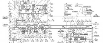
Layout diagrams of plate conveyors are shown in Fig. 32-36.
Fig.32. Schematic diagram of the location of inclined and horizontally inclined plate conveyors in the assembly of a crank hot stamping press: 1-crank hot stamping press; 2-edging press; 3-induction heaters; 4-inclinable plate conveyor; 5-horizontal inclined plate conveyor
Rice. 33. Layout of plate conveyors in the stamping hammer unit: 1 - heating furnace; 2 - plate conveyor; 3 — stamping hammer; 4 - plate conveyor; 5 - trimming press; 6 - plate conveyor; 7 - jobs
Rice. 34. Layout of plate conveyors in the crank hot stamping press unit: 1 - crank hot stamping press; 2 - trimming press; 3 - induction heaters; 4-6 - plate conveyors; 7 - jobs
Rice. 35. Layout of inclined plate conveyors and a stationary plate conveyor in a line of horizontal forging machines: 1 - horizontal forging machines; 2 — pits of horizontal forging machines; 3 - inclined plate conveyors; 4 - stationary plate conveyor; 5 - heating furnaces; 6 — single-rail track; 7 - workplace
Rice. 36. Layout of a stationary plate conveyor in a line of light stamping hammers: 1 - stamping hammers; 2 - heating furnaces; 3 and 4 — slides; 5 - stationary plate conveyor