The 6M82 universal cantilever milling machine is designed for milling the planes of small parts of various configurations made of steel, cast iron and non-ferrous metals using cylindrical, disk, face, shaped and other cutters. The wide technical characteristics of the machine allow the use of high-speed tools. It is used in single, serial and large-scale production.
Desktop Settings
Kinematic diagram
The work table is designed for fixing the workpiece and its further feeding to the surface of the cutting tool - the milling cutter. The main characteristics of this component of the 6Р82Ш universal milling machine is the degree of displacement of the part.
Changing the position of the desktop can be done in two modes - mechanical and manual. In this case, the maximum and minimum parameters will be the same. The maximum load on the table is 250 kg. This only applies to the center. When the center of gravity of the workpiece shifts, this parameter will be smaller.
Main characteristics of the work table of the 6Р82Ш machine:
- maximum movement. Longitudinal - 80 cm, transverse - 24 cm. The maximum possible vertical movement is 41 cm;
- number of T-shaped slots - 3;
- shifting the table by one dial. For one longitudinal or transverse turn it is 6 mm. For vertical movement the value is 2 mm;
- number of working feeds - 18;
- feed limits (longitudinal and transverse) - from 25 to 1250 mm/min.
When mechanically shifting the position of the desktop using the handle, the direction of its rotation coincides with the direction of movement of the entire structure. This reduces the complexity of the work and minimizes the likelihood of errors.
Benefits and Features
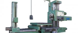
The production of 6р82 cantilever milling machines began in the early 70s of the last century. This model was released to replace the previous device and was designed to improve the process of milling work.
Cantilever milling machine 6Р82 manufactured in 1978
The main advantages of this technique include:
- ease of control when choosing speed modes and feeds with one turn of the dial;
- operation of the unit on the principle of direct current, with the help of which it stops;
- the ability to turn the spindle on and off with a single button;
- Convenient location of the on and off button, as well as the handle on the left side of the device.
The convenience of working with this unit lies in the fact that during operation its levers move in the same direction along with the table on which it is located. This significantly facilitates the work of the master, especially on horizontal milling machines 6р82.
The main technical characteristics of the device are as follows:
- 6р82 corresponds to class N according to the accuracy criterion;
- the working surface (table) of the unit measures 1250 mm in length and 320 mm in width;
- the spindle of the device is equipped with 18 speeds, thanks to which it can make over 1500 revolutions per minute;
- The recommended voltage for operation is 380 V;
- for operation of a horizontal console milling machine, a motor current of 63 A is recommended;
- The machine equipment includes a pump that produces 22 l/min of coolant and has a power of 0.13 kW;
- the installation has 2 engines, one of which is a 4A90L4UZ engine with a power of 2.1 kW, the other is a 4A132M4UZ engine with a power of 7.4 kW.
Engine 4А90L4УЗ
In addition to the specified mechanisms, the device contains auxiliary equipment in the form of:
- intermittent automatic feed designed for longitudinal direction;
- switching stops;
- separate blocking of feed switching;
- blocking mode for both manual and mechanical feed.
The working surface of such a device can move longitudinally by 801 mm, transversely by 249 mm.
The device can process frames, grooves, gears, corners.
Overall dimensions of the workspace
The parameters of the working area characterize the dimensions and design of the work table, specify the connecting bases of the spindles and the relative position of the trunk with other nodes.
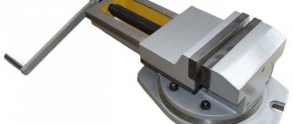
The workpieces being processed are secured to the table using mechanical or hydraulic (less commonly) clamps/clamps. The desktop is provided with T-shaped fastening slots, the dimensions and design of which comply with the technical requirements of GOST 1574-91. There are three through grooves in total on the table. The distance from the longitudinal axis of the desktop to the surface of the vertical stand should be 250-260 mm. which determines the maximum transverse dimensions of workpieces milled on a stationary table.
At the highest horizontal feed of the table, this parameter can be increased, but not more than up to 900 mm. Otherwise, an overturning moment occurs, which increases the load on the clamps and leads to a decrease in the accuracy of metal cutting. For safety reasons, hydraulic clamps are not recommended for use if the table is located far from the side plane of the vertical stand of the machine.
The maximum vertical adjustment of the work table is 450 mm, while the dimensions of the original workpiece in the transverse direction cannot exceed 560 - 570 mm. In order to eliminate impact forces during rough milling of surfaces with complex terrain, the gap between the lower surface of the cutter and the upper part of the workpiece at the initial moment of processing cannot be less than 15 mm.
The length of the working part of the table is 1600 mm; installation of longer workpieces is allowed if they do not interfere with the rotation of the trunk and tool heads. The lower supporting surface of the workpiece must coincide with the supporting surface of the table by at least 75%, while possible gaps are checked using feeler gauges in accordance with GOST 882-75.
The dimensions of the working space are also influenced by the dimensions of the seats for the cutters. In particular, the transverse size of the cutter shank, which is installed in a horizontal spindle, is 29 mm, and the cutter that is installed in the head is 19 mm. Other sizes are determined by the technical requirements of GOST 836-72.
Setting Automatic Mode
For cantilever milling machines of the “M” and “P” modifications, the longitudinal movement of the table is adjusted in automatic or semi-automatic mode. In single production, feed control is performed manually, including rapid table movement. Serial production involves the use of automatic and semi-automatic ranges. In essence, these modes represent a spasmodic and pendulum mode of action.
To adjust the process accordingly, the distance between the cams is made in a T-shaped slot on the side according to a certain indicator. At the right moment, these elements act on the control sprocket with quick working movements of the table on the longitudinal feed switching handle, which makes it possible to guarantee the operation of the equipment according to a given cycle.
The main operating cycles of a cantilever milling machine are listed below:
- Jumping semi-automatic mode.
- Quick feeds to the right and left back.
- A similar operation to the left and the opposite direction to the right.
- Active feeding of the workpiece followed by stopping.
- Pendulum automatic cycle.
- Operations on the machine are only in the right or left direction.
The setup process is carried out in the following sequence:
- The machine must be disconnected from the power supply.
- The mode switches are placed in the desired position (“Automatic control”).
- The unit is activated by pressing the “On” button.
- The cams are installed in the appropriate position.
- Feeding to high speed and back is carried out at any stage and direction of movement, with the exception of the restriction zone for possible operation of the elements.
- Correction of automatic or manual movement of the table is carried out in a neutral position by longitudinally pressing the handle until it stops. If it is impossible to fix the flywheel at the end, turn the adjusting screw.
Design Features
The 6M82 universal cantilever milling machine was developed by a team of GZFS specialists. The equipment has design features that distinguish it favorably from similar models:
- the table rotates 45⁰ in both directions around the vertical axis;
- the ability to automate machines through the use of digital display and connection of operational control;
- the table moves simultaneously along 3 axes;
- Contactless quick-action clutches are installed in the feed drive;
- components are lubricated automatically;
- the working feed in an automatic cycle may slow down;
- you can install a DC electric motor in the feed drive;
- unlimited range of work in automatic mode, including processing along the contour - frame;
- a large number of feeds in a wide range;
- there is a feed slowdown mechanism;
- quick tool change.
Kinematic diagram
A special feature of the equipment design is that the feed drive operates from a separate flange electric motor mounted on the console. The machine has 18 automatic feeds.
Electrical diagram
All equipment - Customize slogan
Designed to perform a variety of milling, drilling and boring operations using cylindrical, face, end, shaped and other cutters. They are used for processing horizontal and vertical planes, grooves, frames, corners, gears, spirals, stamp models, molds and other parts made of steel, cast iron, non-ferrous metals, their alloys and other materials.
The machines are equipped with a trunk on which are mounted overhead and rotary spindle heads with an individual gearbox and a separate drive, providing the ability to process a part with a tool mounted to the working surface of the table at any angle in any plane. The presence of a separate horizontal spindle allows these machines to be used as conventional horizontal milling machines.
The drive power and high rigidity of the machines allow the use of cutters made of high-speed steel, as well as tools equipped with plates made of hard and super-hard synthetic materials.
MAIN ADVANTAGES OF WIDELY UNIVERSAL MACHINES: CONSTRUCTION:
- mechanized tool fastening in the spindle;
- a device for periodically adjusting the size of the gap in the longitudinal feed screw pair;
- safety clutch protecting the feed drive from overloads;
- spindle braking when stopping using an electromagnetic clutch.
- various automatic machine operation cycles;
- wide range of spindle speeds and table feeds;
- high drive power;
- increased accuracy class;
- possibility of simultaneous operation of two spindles;
- high rigidity;
- reliability and durability
TECHNOLOGICAL FEATURES OF THE MACHINES:
The technological capabilities of machines can be expanded through the use of dividing and slotting heads and a round rotary table. 6Т82ШФ1 machines are equipped with a digital coordinate indication device LIR.
| Technical characteristics of the machine 6Р82Ш | Options |
| Type | Widely versatile |
| Dimensions of the working surface of the table, mm | 1250x320 |
| Maximum table movement, mm: | |
| - longitudinal | 800 |
| - transverse | 320 |
| -vertical | 420 |
| Distance from the axis of the horizontal (end of the vertical) spindle to the working surface of the table, mm | 30-450 |
| Distance from the axis of the horizontal spindle to the trunk guides, mm | 155 |
| Spindle speed limits, min-1: | |
| -basic | 31,5-1600 |
| - overhead and rotary heads | 50-1600 |
| Table feed range, mm/min: | |
| -longitudinal and transverse | 0-3150 |
| -vertical | 0-1300 (accelerated 4000) |
| Maximum mass of the workpiece (with fixture), kg | 400 |
| Power of electric drive motors, kW: | |
| - main spindle | 7,5 |
| - overhead and rotary heads | 3 |
| - table feeds | 3 |
| Spindle cone according to GOST 30064-93 | |
| -basic | N50 |
| - overhead and rotary heads | N40 |
| Angle of rotation of the table around the vertical axis, degrees. | — |
| Overall dimensions of the machine, mm | |
| - length | 2280 |
| - width | 1965 |
| - height | 1970 |
| Weight of the machine with electrical equipment, kg | 3550 |
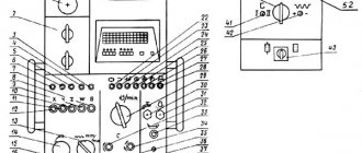
Description of electrical equipment
The electrical equipment of the 6M82 machine model operates on a current of 380 V with a frequency of 50 Hz. To power the control circuit, the current was reduced to 127 V, the lighting operates from a 36 V network. Overload protection is installed at the zero phase of the electric motor. Fuses prevent short circuits in the machine network.
Reference! Equipment for 220 V and 500 V voltages was produced for individual enterprises and for export.
There are niches in the frame for electrical equipment. Each has two panels connected into a common circuit. On the left is the handle to turn on the power to the entire unit. The spindle has a push-button control with a reversible rotation direction switch. The feed motor is activated by two control devices:
- longitudinal movement;
- lateral and vertical movement.
Operating modes are started in the electrical circuit of the control unit - by a start switch having 3 operating positions:
- automatic cycle;
- feed from handles;
- round table.
The electric pump pumping coolant is switched on. There is a switch for the light bulb on the local lighting lamp. The EB electromagnet is located on the high-speed friction clutch and turns it off when the mechanical feed is turned on.
Braking is carried out by a bias current directed by a selenium rectifier to the electric motor. Quick engagement of gear wheels is accomplished with a “push”. When switching speeds, a short-term reverse movement of the spindle occurs until the teeth engage.
Related Posts via Categories
- Shell end mill – high-quality cutting of steel and cast iron
- Do-it-yourself copy-milling machine - we create reliable equipment!
- Mini milling machine - how to assemble it yourself?
- Homemade metal milling machine - assembled without problems!
- Dividing head for milling unit and other devices
- Milling and engraving machine - a high-precision unit with program control
- Turning and milling machine – what gives us its versatility?
- Tabletop CNC milling machine – high-precision machining of small products
- Corvette 83 – reliable equipment for milling wood blanks
- NGF-110 (Sh4) – a reliable and efficient training milling unit
Installation drawing
The drawing is calculated individually depending on the room. The standard drawing is presented so that the equipment fits when rotated 45 degrees on any plane.
Limits of machine use in terms of power and power loads
The operating limits of the drive are determined only by the indicators of the electric motor installed in the equipment (if carried out at more than 63 revolutions per minute). If the number is less than 63, then the power of the main drive is reduced. The cutting force for longitudinal feed is a maximum of 1500 kgf, transverse - 1200 kgf, vertical - 500 kgf. The maximum workpiece size for roughing is up to 160 millimeters.
Connecting bases for milling machine 6M82. Trunk, earrings and spindle.
The connecting base consists of: trunk, earrings and spindle.
Trunk
The trunk serves to support the free end of the milling mandrel. For this purpose it is equipped with special pendants. The other end of the mandrel is attached to the spindle cone using a bolt. The trunk is attached to the guide profiles and can move along them thanks to a gear rack.
The trunk is attached to the frame at the front and back with two clamps. Both clamps must be fully tightened. The front protrusion of the trunk is usually equipped with two earrings, tightened with a nut (less often - one).
Earring
Each earring has a bearing in the form of a bronze bushing. This bushing helps control the clearance in the plain bearing.
It is very important to monitor the oil level in the inner recess of the earring. Sometimes, in order to give the trunk additional rigidity, it is equipped with support posts that are attached to the console. But in this case, vertical feeding is not allowed and the convenience of operation is lost.
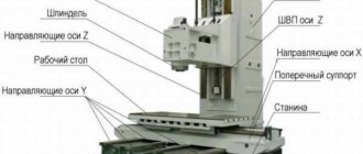
Location of components
bed
Technical characteristics, design and diagrams of the horizontal milling machine model 6р82
The basis of the cantilever milling installation is the bed. It is equipped with vertical and horizontal guide profiles. The consoles move along the first ones, and the trunk moves along the second ones. The gearbox was placed in the inner part of the body.
The side walls have closed recesses with electrical equipment. On the right is a switch with three modes:
- Automatic mode (for many identical operations)
- Handle feed (standard operation)
- Round table (for milling with platform rotation without interruption)
Console
The purpose of the console is to change the vertical position of the table. The engine built into the console is responsible for accelerated movements and feeds. The speed is controlled by the front handle.
Sled
This element can be moved with a rotating plate or with a work surface. This ensures cross feed. The table can move longitudinally along the guide profiles.
Table
The parts to be milled are mounted on the table. Moreover, they can be moved along the surface. The product is fastened with bolts screwed into the grooves of the table. In front there is also a groove for cams, which switch the longitudinal movement of the platform automatically.