Widely universal milling machine 6T83Sh is a universal metalworking machine designed for boring, drilling and milling work using end, shaped, face and cylindrical cutters.
Functional Features
The highly versatile milling machine 6T83Sh is used for processing the following types of metal surfaces:
- horizontal and vertical planes;
- stamps;
- grooves;
- Press forms;
- corners;
- gear wheels;
- spirals;
- framework;
- other forms of products made of non-ferrous metals, various grades of steel and cast iron, alloys.
Separately, we should highlight some functional features of the widely-universal milling machine 6T83Sh, which determine the specifics of its use in practice:
- several automatic milling cycles;
- possibility of working at an angle to the desktop;
- ability to work with several cutting tools simultaneously.
Design features
The highly versatile milling machine 6Т83Ш has a number of important design features, among which we should especially highlight:
- trunk with overhead and rotary spindle heads, each of which is equipped with its own gearbox and individual drive;
- mechanized device for fastening the working tool in the spindle;
- safety clutch for permanent protection of the drive from overloads;
- mechanism for regulating the linear gap in the feed screw pair (longitudinal);
- spindle braking mechanism with an electromagnetic clutch;
- The widely-universal milling machine 6T83Sh has a rigid, vibration-resistant design.
The highly versatile milling machine 6T83Sh is an industrial metalworking equipment used in individual and mass production in tool and mechanical repair shops.
The machine uses a horizontal spindle when processing planes with face and cylindrical cutters; separate and simultaneous operation with both spindles is possible; there is a device for limiting the gap in the screw pair of longitudinal movement of the table.
The machine can process vertical and universal planes, grooves, corners, frames, gears, etc.
To process various types of surfaces, as well as large-sized models that exceed the dimensions of the table, the spindle head is mounted on a retractable trunk and can be rotated at an angle in two mutually perpendicular planes.
The machine is equipped with a horizontal spindle, which can be used when processing planes with end and cylindrical cutters.
Both separate and simultaneous operation of two spindles is provided. When installing the earrings supplied with the machine, the machine can be used as a horizontal milling machine.
To expand the capabilities of the machine, in addition to the earrings, an additional overhead rotating head is included. The overhead head allows you to process large parts, as well as perform simple boring work.
The presence of a backlash sampling mechanism in the screw pair of the longitudinal feed of the table allows for up and down milling both in simple modes and in modes with automatic cycles.
Milling of gears, reamers, cam contours and other parts that require periodic or continuous rotation around their axis is carried out on these machines using a dividing head or an overhead round table.
Lubrication of the console guides and the table-slide assembly is carried out centrally from a plunger pump. Thanks to effective lubrication, the durability of these components increases, the original accuracy is maintained longer and maintenance time is reduced. The roughness of the treated surface is Rz 20 µm. Machine accuracy class P.
The technological capabilities of the machine can be expanded with the use of a dividing head, a rotary round table, an overhead universal head and other devices.
The machine is equipped with a trunk on which overhead and rotary spindle heads are installed (rotary spindle head for machines 6Т82Ш-35, 6Т82Ш-36 and 6Т83Ш-35, 6Т83Ш-36) with an individual gearbox and a separate drive, providing the ability to process a part with a tool mounted to working surface of the table at almost any angle in any plane.
Technological design features of the 6T83Sh machine:
- drilling and boring at any angle
- processing of a part from 5 sides with one installation (with an overhead head)
- the ability to work in automatic cycles in 3 coordinates, including processing (cycle) along the frame;
- slowing down the working feed in the automatic cycle;
- Possibility of simultaneous operation of two spindles
The durability of the machine and rigidity have been increased due to the rectangular guides of the frame and console, the lifting force of the console has been reduced due to individual lubrication of the vertical movement screw, additional devices have been introduced to protect against flying chips and emulsions.
The technical characteristics and high rigidity of the machines allow full use of the capabilities of both high-speed and carbide tools.
To reduce auxiliary time and ease of control, the machines provide:
- duplicated push-button-handle control (front and left side of the machine);
- starting and stopping the spindle and turning on the high speeds of the machine using buttons;
- control of table movements from handles, the direction of rotation of which coincides with the direction of movement of the table;
- changing speeds and feeds using single-handle selective mechanisms, allowing you to obtain any speed or feed by turning the dial without going through intermediate steps;
- DC braking.
The machines are automated and can be configured for various automatic cycles, which increases labor productivity, eliminates the need to maintain the machines by highly qualified workers and facilitates the possibility of organizing multi-machine maintenance.
Machine accuracy class P according to GOST 8-77.
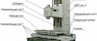
Location of components on the 6T83Sh machine
Location of components on the 6T83Sh machine
List of components of the 6T83Sh milling machine
- bed - 6T83G.10.000-07;
- switching box 6Р83.5;
- side remote control - 6T82G-1.85A;
- gearbox 6Т83Ш.30;
- set of electromechanical tool clamping device - 6Р13К.93.100-03
- trunk - 6Т83Ш-1.150;
- rotary head - 6Т82Ш-1.310;
- overhead head - 6Т82Ш-1.320;
- control cabinet - 6Т83Ш-29.811;
- table and slide - 6T83G-1.70.000-07;
- feed slowdown mechanism;
- main remote control - 6T82G-29.821;
- console - 6Т83Ш-29.600;
- feed box - 6T82G-1.40
Location of controls for the 6T83Sh milling machine
Location of controls for the 6T83Sh milling machine
List of controls for the 6T83Sh milling machine
- Spindle speed indicator
- Spindle Start button (duplicate)
- Switch “Clamp - tool release”
- Button “Move table right - forward - down”
- Switch for selecting the direction of table movement
- Button “Move table left - back - up”
- Button “Stop table movement”
- Spindle Jog button
- “Spindle Stop” button (duplicate)
- Emergency Stop button
- Button “Fast table movement” (duplicate)
- Spindle speed shift knob
- Spindle push button of rotary head
- Rotary head spindle speed shift knobs
- Manual movement of the trunk
- Earring clips
- Swivel head clamp
- Spindle sleeve extension handwheel
- Spindle sleeve clamp handle
- Slide Clamps
- Button “Move table left”
- Button “Move table to the right”
- Table Clamps
- Switch for switching on the table operating mode “Manual - Mechanical”
- Flywheel for manual longitudinal movement of the table
- Ring - vernier
- Limb of the table transverse movement mechanism
- Manual lateral movement of the table
- Manual vertical table movement
- Feed switch mushroom
- Button "Move table forward"
- Button “Move table backwards”
- Emergency Stop button
- Spindle start button
- Switch for selecting machine operating modes
- Spindle Stop button
- Button “Fast table movement”, “Start cycle”
- Button “Move table down”
- Button “Move table up”
- Flywheel for manual longitudinal movement of the table (duplicate)
- Trunk clamp on the frame
- Input switch
- Spindle rotation direction switch “Left - Right”
- Cooling Pump On/Off Switch
- Switch the direction of rotation of the spindle of the overhead head "Left - right"
- Auto cycle selection switches
- Control panel selection switch
- Console Clamp
- Handle for manual vertical and transverse movements of the table (removable)
- Overhead clamp
- Zero fixation pin
- Power button of the zero release of the input switch
Specifications
Main technical characteristics of the machine:
- maximum table movement along – 1 meter;
- maximum table movement across and vertically – 40 cm;
- 11 vertical spindle speeds;
- 18 horizontal speeds;
- spindle quill movement – 8 cm;
- the quill moves 6 mm per revolution of the dial;
- distance from the horizontal spindle to the trunk – 19 cm;
- from the end of the spindle of the rotary head to the work table, the distance is 16–58 cm.
The limits of vertical working feeds of the table are in the range of 4.1–530 mm/min.
Kinematic diagram of the universal cantilever milling machine 6Т83Ш
bed
The bed is the main assembly unit on which the components and mechanisms of the machine are mounted.
The rigidity of the frame structure is achieved due to the developed base and a large number of ribs.
The console moves along the vertical guides of the frame, and the trunk moves along the horizontal guides.
To limit the travel of the console, a bar with cams is attached to the left side of the frame.
A control station is installed on the right side of the frame.
The electric motors of the main movement and the tool fastening mechanism are flanged to the rear of the frame.
There is an oil reservoir inside the frame body. The frame is installed on a base, which also serves as a support for the console lifting screw. A coolant supply pump is installed at the rear of the base.
Trunk and gearbox of the spindle of the rotary head of the 6T83Sh milling machine
Trunk and gearbox of the spindle of the rotary head of the 6T83Sh milling machine
The trunk is an independent assembly unit. The gearbox (Fig. 16) of the rotary head spindle drive is mounted in it. Changing the spindle speeds is carried out by moving the gear blocks along the splined shafts using handles 14 (Fig. 13) in accordance with the plates installed on them.
The trunk is moved in the frame guides by rotating the handle 15. Before moving the trunk, it is necessary to unscrew the screw 45 four to five turns to obtain an easy move.
If it is necessary to use the machine as a regular horizontal one, earrings can be installed on the trunk guides (Fig. 15). The boring of the earring hole for the bearing is made individually for each machine, therefore, REPLACEMENT OF EARRINGS FROM ONE MACHINE TO ANOTHER IS PROHIBITED.
As a rule, on the 6T82Sh machine one of the earrings I or II is used; on the 6T83Sh machine - earring II; for heavy processing conditions on the 6T83Sh machine, two earrings II can be used.
Section of the rotary head of the wide-universal milling machine 6Т83Ш
Section of the rotary head of the wide-universal milling machine 6Т83Ш
The rotating head is attached to the trunk through the intermediate plate 1 using bolts inserted into the annular T-shaped groove and is centered in the annular recess (Fig. 16).
The rotating head is fixed in the zero position in relation to the trunk flange. To rotate the head, release it from the zero fixation by rotating the nut of the fixation pin and pulling out pin 55 (Fig. 13).
The spindle of the rotating head receives rotation from the trunk speed box through the cam clutch 1 and bevel gears 2, 3 (Fig. 17) and 4, 5 (Fig. 18).
The spindle is a two-support shaft mounted in a retractable sleeve.
The rotary head sleeve is moved by a handwheel connected by a worm and a gear to a rack cut into the spindle sleeve.
The sleeve clamping mechanism includes a fixed stop 1 (Fig. 19) and a rod 2.
Overhead head of the wide-universal milling machine 6Т83Ш
Overhead head of milling machine 6Т83Ш
The overlay head is attached to the swivel head via a T-slot. The spindle of the overlay head receives rotation from the spindle of the rotary head (Fig. 20).
Gearbox of machine 6Т83Ш
The horizontal spindle gearbox is mounted directly in the frame body. The connection of the box with the electric motor shaft is carried out by an elastic coupling. Two triple and one double gear block are mounted on the intermediate shafts. An electromagnetic clutch II (Fig. 21) is installed on the motor shaft, which serves to brake the spindle when stopping.
The gearbox can be inspected through the window on the right side of the frame.
Machine spindle
The machine spindle (Fig. 21) is a two-support shaft, the geometric rotation accuracy of which is determined mainly by bearings 2 and 4.
Gearbox for machine 6Т83Ш
Speed change box for milling machine 6Т83Ш
The gearbox allows you to select the required speed without sequentially passing through intermediate stages.
Rack 1 (Fig. 22), moved by shift handle 5, through sector 2 through fork 10 (Fig. 23), moves roller 3 with shift disk 9 in the axial direction. The shift disk is turned by the speed indicator 11 through bevel gears 2 and 4. Disk has several rows of holes of a certain size, located against the pins 8 of the racks 5 and 7, meshing in pairs with the gear 6.
A shift fork is attached to one of each pair of rails. When moving the disk by pressing on the pin of one of the pair, reciprocating movement of the slats is ensured. In this case, the forks at the end of the disk stroke occupy a position corresponding to the engagement of individual pairs of gears. To eliminate the possibility of hard stop of the gears when switching, the pins of the 8 racks are spring-loaded.
Fixation of the dial when choosing a speed is ensured by ball 1, which slides into the grooves of sprocket 12.
Adjustment of spring 13 for clear fixation of the dial and normal force when turning it is carried out by plug 14.
Handle 5 (Fig. 22) in the on position is held by spring 4 and ball 3. In this case, the handle tenon fits into the groove of the flange.
Correspondence of speeds to the values marked on the indicator is achieved by a certain position of bevel gears 2 and 4 (Fig. 23) along the mesh. Correct engagement is established by cores at the ends of the mating tooth and cavity or by setting the pointer to the speed position of 31.5 rpm and the disk with forks to the speed position of 31.5 rpm.
The gap in the engagement of the conical pair should not be more than 0.2 mm, since the disk can rotate up to 1 mm due to this. The gearbox is lubricated by the gearbox lubrication system by spraying oil coming from a tube at the top of the frame. Lack of oil rain can cause unacceptable heating of the shift fork jaws and lead to fork binding, deformation or failure.
Feed box of machine 6Т83Ш
Feed box for milling machine 6Т83Ш
The feed box ensures that the table moves along three coordinates at a given speed.
Rotation to the input wheel 1 (Fig. 24) of the feed box comes from the ring gear 5 (Fig. 26) mounted on the console shaft 7. The speeds obtained as a result of switching the gear blocks through the output wheel 3 (Fig. 24) and the parasitic gear 20 (Fig. 26) are transmitted to the feed clutch 18 installed on the output shaft 16 of the rapid speed chain located in the console. The feed box and the rapid speed chain are protected from damage due to overloads by a ball safety clutch 22.
The amount of torque developed by the clutch is regulated by changing the force of the springs acting on the balls located in the grooves at the end of the gear. When the feed mechanism is overloaded, the balls, overcoming the forces of the springs, are squeezed out of the grooves, and the gear 21 begins to slip relative to the shaft 16. At the same time, the working feed stops.
The clutch adjustment is considered correct if it does not engage when the console is quickly moved up.
To achieve a tight junction between the feed box and the console, a rectangular groove is made along the perimeter of the end flange of the box, into which a sealing cord Ø5 mm made of oil- and petrol-resistant rubber is inserted. The supply of lubricant to the feed drive units is carried out by a plunger pump driven by ball bearing 2 mounted on the eccentrically made hub of the input wheel 1 (Fig. 24).
Feed switching mechanism
Feed switching mechanism of milling machine 6Т83Ш
The feed switching mechanism (Fig. 25) includes disk 7 rigidly connected to shaft 6, disk 2 movable along the shaft axis, and rods 5 with switching forks. When switching, the disks move in the opposite direction and, acting on the ends of the rods, move them and the associated blocks of switchable gears in the axial direction. The specified direction of movement of the rods (right-left) is ensured by the presence of holes in the disks located opposite the corresponding ends of the rods. The disk hub 7 is equipped with an annular groove and a gear 8, through which the feed switching mechanism is connected to the control shaft 9.
To switch the feed, you need to press button 14 and pull out the fungus 13 until it stops. In this case, shaft 9 will pull the associated shaft 6 with disk 7, Disk 2, connected by means of rack 1 and gear 21 with shaft 6, in this In this case, it will move in the opposite direction until its hub stops against screw 4, and the ends of the rods will be freed from interaction with the disks. By subsequent rotation of the fungus 13 around its axis, set the required feed amount along the dial 11 against the indicator arrow 10.
The feed is switched by moving the fungus in the axial direction to the initial fixed position. If it is not possible to send the fungus to its original position, then you should repeat the movement towards yourself again. In this case, the action of the disk 20 through the pusher 19 will close the contacts of the limit switch 18, which controls the pulse activation of the feed motor, after which the fungus will return to its original position without difficulty.
Displacement of disks 2 and 7 in the axial direction is prevented by fixing shaft 9 in the on position with two balls 16 and a sleeve 15. When button 14 is pressed, the balls fall into the annular groove of the roller 17 and release shaft 9 from fixation. The rotation of the shift disks is fixed by a spring-loaded ball 3, located in the hole of the rack 1.
Console
Console of milling machine 6Т83Ш
The console is the basic unit that unites the nodes of the machine feed chain. A chain of accelerated movements, a box for distributing movements along the lead screws and a control shaft for the feed switching mechanism are built directly into the console body. On the left side of the console there is a removable feed box with a pipe for filling oil, and there are also indicators for pump operation and oil level in the oil tank of the console. On the right side are mounted the feed electric motor and the distribution box for powering the electromagnetic clutches, located under the protective casing of the electric motor.
The presence of a distribution box with terminal strips allows you to ring the circuit of any of the electromagnetic clutches in the feed drive without opening the console.
At the front end of the console there is a button for periodically supplying oil to the table and slide guides. The feed switching fungus is also located here.
The console body is divided by a transverse partition into two compartments. A coupling box for distributing movements along the lead screws is built into the front compartment. Access to the couplings during inspections and repair work is carried out through the side windows: through the right one - to the safety and transverse clutches, through the left - to the vertical displacement couplings.
Dismantling and installation of longitudinal clutches is carried out through a hole in the front wall of the console, closed by the supporting flange of the clutch shaft bearing.
When dismantling shafts with clutches for transverse and vertical movements of the table, do not disturb the initial setting of the position of the blocking limit switches, which ensure that the electromagnetic clutches are disconnected when using the removable adjustment movement handle.
The rapid speed chain consists of two pairs of permanently meshed gears mounted on shafts 11, 7 and 16 (Fig. 26), gears 9, 6 and 3 of these gears are rigidly connected to shafts 11 and 7, and the driven wheel 15 rotates freely on shaft 16 and is rigidly connected to it when the rapid clutch 14 is closed.
On the shaft. 16, in addition to the high-speed clutch, there are feed clutches 18, as well as a safety clutch 22, through which the movement is transmitted to the transmission box via the lead screws,
From the coupling shaft 25 through gears 2 and 1, rotation is transmitted to the screw for transverse movements 32. The screw for vertical movements receives rotation from shaft 27 through a cylindrical gear pair 29, 30 and bevel gears 5 and 4 (Fig. 27).
Rotation to the longitudinal displacement screw is transmitted from shaft 28 by means of a double block 26, freely installed at the end of the transverse displacement screw, to the splined shaft 31.
Next, rotation through two bevel pairs of gears 12, 13 and 14, 4 is supplied to sleeve 10 (Fig. 28), connected to the longitudinal displacement screw 1, through a sliding key.
Table and slide
Table and slide of milling machine 6Т83Ш
The table and slide (Fig. 28, 29) provide longitudinal and transverse movements of the table.
Lead screw 1 (Fig. 28) receives rotation through the sliding key of the sleeve 10, mounted in the sleeve 7. The sleeve 10 through the splines receives rotation from the gear half-coupling 6 when engaging it with the gear half-coupling 5, rigidly connected to the bevel gear 4. The half-coupling 5 has the ring gear with which the round table drive gear meshes. The coupling half 6 has a toothed rim for rotating the longitudinal feed screw when moving from the flywheel 5 (Fig. 29). Rotation to the ring gear is transmitted from gear 4, which is spring-loaded in case of tooth contact. The engagement of the ring gear 3 of the coupling half with the gear 4 is possible only if the coupling half 6 is disengaged from the coupling half 5 (Fig. 28) and is carried out by moving the rack 1 (Fig. 29) from the switch 6 mounted on the roller 2. In this way, the flywheel 5 is blocked.
Nuts 2 and 3 of lead screw 1 (Fig. 28) are located on the left side of the slide. The right nut 3 is fixed with two pins in the slide body; the left nut 2, resting its end against the right one, when turning it with a worm, selects play in the screw pair.
The table is connected to the lead screw through brackets, the installation of which at the ends of the table is carried out according to the actual location of the screw and is fixed with control pins. Thrust bearings are mounted at different ends of the screw, which eliminates the possibility of its operation in longitudinal bending. When installing the screw, the lead screw is preloaded with nuts with a force of 1000...1250 N (100...125 kgf).
The clamping of the slide on the console guides is ensured by strips 9, which are acted upon by the eccentric of the roller 8.
Electromechanical tool clamping device
Electromechanical tool clamping device for machine 6Т83Ш
The electromechanical tool clamping device (Fig. 30) is designed to secure the tool in the machine spindle.
Tightening and ejection of the tool is carried out using a moving rod 3 located inside the spindle 5. The reciprocating movement of the rod 3 is ensured by its threaded connection with the splined roller 2, which receives rotational movement from the head of the electromechanical clamp of the tool 1. At the end of the rod 3 there is a T-shaped head , which connects to the T-shaped groove of the gripper 4, screwed into the mandrel with the cutter.
Installation of cutters on mandrels is carried out depending on their size and type (Fig. 31).
Grip 1 (Fig. 31) must be installed so that the T-shaped groove of the grip is perpendicular to the leading grooves of the mandrel or cutter 3 and the size is 43 ± 1.5 mm.
The range of mandrels and adapter bushings supplied with the machine is given in section 3 “Delivery set”.
The milling mandrel is secured in the spindle in the following sequence: insert the mandrel with the cutter into the tapered hole of the spindle and connect it to the head of rod 2 by turning it at an angle of 90°. Set switch 3 (Fig. 13) to the “Tool clamp” position. In this case, the mandrel with the cutter is pulled into the spindle. The end of the clamping is determined by the clicking of the claw coupling of the mechanism.
When spinning the tool, you must: turn off the spindle with button 9 or 39 (Figure 13) and make sure that the spindle stops. Switch switch 3 to the “Tool release” position and hold until the milling mandrel comes out of the spindle to a length of no more than 15... 20 mm, i.e. the mandrel should disengage from the spindle drive keys.
With greater movement of the mandrel, roller 2 (Fig. 30) can be completely turned out of rod 3. Then, when clamping the tool, the rod must be pressed along the axis so that the threaded end of the roller is screwed into the threaded hole of the rod. ATTENTION! WHEN THE SPINDLE IS INITIALLY TURNED ON, IT IS NECESSARY TO CLAMP THE TOOL.
Clamp the tool when the machine spindle speed set on the dial is no more than 400. When checking the rotation of the spindle without a tool, it is necessary to idle pull rod 3 until the cam clutch clicks, simulating clamping the tool, otherwise the spindle will not turn on. For end mills with a conical shank having a Morse taper of 5, an adapter sleeve with a taper of 7:24 is used (Fig. 32).
Installation drawing of milling machine 6Т83Ш
Installation drawing of milling machine 6Т83Ш
Repair of milling machine 6Т83Ш
Machine inspection
- External inspection of the machine (without disassembling to identify defects) of the condition and operation of the machine as a whole and by components;
- Inspection and check of the condition of the main movement and feed drive mechanisms;
- Adjusting the table lead screw clearances;
- Spindle bearing adjustment;
- Checking the operation of speed and feed switching mechanisms;
- Regulation of the mechanisms for switching on cam clutches and feeds and the high-speed friction clutch;
- Adjustment of table wedges, slides, console and trunk;
- Inspection of guides, cleaning of nicks and burrs;
- Tightening loose fasteners;
- Checking the operation of the limiting cams;
- Checking the condition and minor repairs of cooling and lubrication systems;
- Checking the condition and repairing protective devices;
- Identification of parts that require replacement during the next repair (starting with the second minor repair);
Small machine repair
- Partial disassembly of components;
- Flushing all components;
- Adjustment or replacement of rolling bearings;
- Cleaning burrs and nicks on gear teeth, crackers and shift forks;
- Replacement and addition of friction discs of the high-speed clutch (starting from the second repair);
- Scraping and cleaning of wedges and strips;
- Cleaning the lead screws and replacing worn nuts;
- Cleaning nicks and burrs on the guides and working surface of the table;
- Replacing worn and broken fasteners
- Checking and adjusting the mechanisms for switching on speeds and feeds;
- Repair of lubrication and cooling systems;
- Testing the machine at idle speed, checking for noise, heating and accuracy of the workpiece.
Average machine repair
- Unit disassembly of the machine;
- Flushing all components;
- Inspection of parts of disassembled units;
- Drawing up a list of defects;
- Adjusting or replacing spindle bearings;
- Replacement or restoration of spline shafts;
- Replacement of worn bushings and bearings;
- Replacement of discs and fastener clutch parts;
- Replacement of worn gears;
- Restoring or replacing worn lead screws and nuts;
- Scraping or replacing adjusting wedges;
- Repair of pumps and fittings of lubrication and cooling systems;
- Correction by scraping or grinding the surfaces of the guides if their wear exceeds the permissible level;
- Painting the external surfaces of the machine;
- Running in the machine at idle (at all speeds and feeds) with checking for noise and heating;
- Checking the machine for accuracy and rigidity according to GOST 17734-72.
Overhaul of the machine
Major repairs are carried out with complete disassembly of all components of the machine, based on the results of which a defective estimate sheet must be drawn up. As a result of the repair, all worn components and parts of the machine must be restored or replaced, and its original accuracy, rigidity and power must be restored. The nature and scope of work for this type of repair are determined for specific operating conditions by a unified system of scheduled preventive maintenance.
Basic information about the machine
6Т83Ш refers to horizontal console-type machines with a wide range of applications (as indicated by the letter Ш in the brand designation). Thanks to the presence of the console, the unit can process:
- Horizontal and vertical surfaces.
- Grooves and protrusions of various shapes and sizes.
- Corners and edges on workpieces.
- Frames of parts.
The main design feature of this machine is the presence of a rotating console of two spindles - vertical and horizontal. Thanks to these factors, the table with the workpiece rotates in the vertical direction, which saves time spent on preparatory transitions and facilitates operator control over the progress of the process. In addition, it is possible to perform not only milling operations, but also chiselling, planing and edge trimming.
The limits of machine use in terms of power and power parameters, as well as the sequence of metal shaping, are calculated based on three parameters - speed and depth of cut, as well as the amount of feed of the rotary table relative to the tool.
Milling speed is determined by the number of revolutions of the cutter per minute and its diameter. The cutting depth depends on the physical and mechanical characteristics of the workpiece metal. The feed is coordinated with the design of the tool (number of cutter teeth) and the desired milling performance. The durability of cutters is also taken into account, which are usually made from such grades of tool steel as R6M5, R6M5K5 (processing simple-shaped workpieces from ordinary carbon steels) or R9M4K8, R12F3K6, R12F2M3K8 - for milling alloyed and special steels with increased strength.
Thermal converters (temperature sensors) are designed to continuously measure the temperature of the working environment. The controlled object can be: vapors, various liquids, gases, bulk materials, chemically active substances (inert to the material of the sensor body).
The model under consideration differs from the 6Р83Ш machines produced by Soviet machine tool enterprises with approximately similar characteristics in a higher-speed drive for moving the work table and an increased range of speeds for the rotational movement of the spindle. This allows you to save overall processing time, especially when milling complex cavities in parts such as dies, molds, and industrial equipment beds.