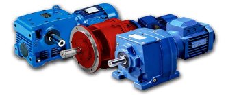
If you decide to purchase a gearbox, you need to clarify in advance for what purpose it will be intended. In this case, it will be possible to understand which design is better to prefer. There are cylindrical and worm-type options on the market. Worm gear motors are widely used. Such devices allow pumps and lifts to operate, thanks to them the functioning of conveyors, the operation of mixers and gates.
If you need to increase torque and at the same time reduce rotation speed, then you will not find a better device. In this case, it is desirable that there are no shock loads, and that the device can operate for quite a long time.
Worm gear
The transmission of rotation and force is often carried out using special mechanisms, which have come to be called gearboxes. Such a product is represented by a combination of several elements, which, when interacting, increase or decrease the gear ratio, change the rotation speed and redirect the force. The worm gearbox has become quite widespread. It is characterized by certain characteristics that must be taken into account. Let us consider the features of such a mechanism in more detail.
Gear ratios
Another important parameter that must be taken into account when correctly selecting the required standard size of a worm gearbox for specific tasks is the ratio of the reduction in the output shaft speed to the rotation speed of the drive motor. This parameter, which depends on the ratio of the number of teeth on the impeller to the number of threads on the worm, is called the gear ratio of the worm gearbox. The reduction coefficient ranges from 5 for single-stage models to 4000 for two-stage models. This coefficient is influenced by the design and number of gear stages.
Design and principle of operation
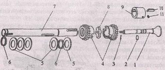
A classic gearbox is represented by a combination of various elements that, when interacting, ensure the transmission of force. The principle of operation of a worm gearbox is associated with the features of the main element, which is a worm-shaped drive screw. It is he who determines the name of the device. In addition, the classic version is represented by a combination of the following elements:
- The gear has a cylindrical shape with teeth on the surface. It has become very widespread and is in direct connection with the worm.
- A shaft is used to secure the gear. It is located at right angles to the worm.
- All elements are located in a housing, which is often made of cast iron. In order to be able to carry out maintenance, the body is made composite, the lower part acts as a fixing element.
- The connection of two housing elements and the fixation of other parts is carried out using various sealing elements. Their use can be associated with the fact that the housing contains oil, which is dispersed during operation to provide the required cooling and reduce wear.
- Shaft rotation is ensured by installing bearings of various types. Quite a lot of attention is paid to this detail, since during the service life of the device it is they that often fail.
The kinematic scheme determines the possibility of transmitting low torque with a high speed of rotation of the input shaft.
At the same time, at the output there is a decrease in the number of revolutions and an increase in force. In addition, the worm gearbox may have the following technical characteristics:
- There are low-speed and high-speed versions. In this case, in the case of a low rotation speed, the worm is installed from below, and in case of a high rotation speed, from above. The low-speed shaft must be properly lubricated, otherwise it will not last long.
- If the rotation of the main parts occurs at high speed, then the oil must be supplied under high pressure. The low-water worm pair can be lubricated without pressure by natural oil circulation.
Today, the gear housing is in most cases made using cast iron, since this material can withstand significant environmental influences. The gear ratio of the worm gearbox depends on the size of the mechanism. A drawing of the device can be found on the Internet; in addition, it is created by an engineer with appropriate training.
When choosing the mechanism under consideration, a variety of parameters are taken into account, but the gear ratio of the worm gearbox can be considered the most important parameter.
NMRV selection
HomeChoice NMRV
Selecting the gear ratio and speed at the output of the gearbox
n1 – number of revolutions at the gearbox input, rpm number of revolutions at the gearbox input depending on the selected type of drive or electric motor.
n2 – number of revolutions at the output of the gearbox, rpm This value is determined by the required number of revolutions for a given mechanism or device.
i – gear ratio of the gearbox. The value obtained by dividing the number of teeth of the worm wheel by the number of starts of the worm shaft: (formula 1)
i = n 1 / n 2
(1)
Selecting a gearbox size based on power
P1 – power at the input shaft, KW power at the gearbox input, depending on the selected type of drive or electric motor.
P2 – power at the output shaft, KW power at the output of the gearbox. This value is determined by the required power for a given mechanism or device.
The dependence of the power at the input to the gearbox and at the output is determined by the following relation: (formula 2)
ŋ d (ŋ s ) = (P 2 / P 1 ) x 100%
(2)
Where:
ŋd – dynamic efficiency of the gearbox. The efficiency values were calculated experimentally for gearboxes based on the results of long-term running-in at normal rotation speed and steady-state operating temperature of the gearbox housing. The values are given in the efficiency table.
ŋs is the static efficiency of the gearbox. This coefficient occurs when the gearbox is started and significantly reduces the torque. In the presence of variable loads (for example, lifting a load), instead of the dynamic coefficient, the static coefficient is decisive. The values are given in the efficiency table.
| Standard size | Efficiency | Gear ratio | ||||||||||
| 7,5 | 10 | 15 | 20 | 25 | 30 | 40 | 50 | 60 | 80 | 100 | ||
| NMRV030 | ηd(1400) | 0.85 | 0.82 | 0.77 | 0.73 | 0.68 | 0.65 | 0.59 | 0.55 | 0.51 | 0.44 | |
| ηs | 0.67 | 0.63 | 0.55 | 0.5 | 0.43 | 0.39 | 0.35 | 0.31 | 0.27 | 0.23 | ||
| NMRV040 | ηd(1400) | 0.87 | 0.85 | 0.82 | 0.78 | 0.75 | 0.7 | 0.65 | 0.62 | 0.58 | 0.52 | 0.47 |
| ηs | 0.71 | 0.67 | 0.6 | 0.55 | 0.51 | 0.45 | 0.4 | 0.36 | 0.32 | 0.28 | 0.24 | |
| NMRV050 | ηd(1400) | 0.88 | 0.86 | 0.82 | 0.79 | 0.76 | 0.72 | 0.67 | 0.63 | 0.59 | 0.53 | 0.49 |
| ηs | 0.7 | 0.66 | 0.59 | 0.55 | 0.51 | 0.44 | 0.39 | 0.35 | 0.32 | 0.27 | 0.23 | |
| NMRV063 | ηd(1400) | 0.88 | 0.87 | 0.83 | 0.81 | 0.78 | 0.74 | 0.7 | 0.66 | 0.62 | 0.57 | 0.51 |
| ηs | 0.71 | 0.67 | 0.6 | 0.55 | 0.51 | 0.45 | 0.4 | 0.36 | 0.33 | 0.28 | 0.24 | |
| NMRV075 | ηd(1400) | 0.89 | 0.88 | 0.85 | 0.82 | 0.8 | 0.76 | 0.72 | 0.69 | 0.65 | 0.6 | 0.55 |
| ηs | 0.71 | 0.68 | 0.61 | 0.57 | 0.53 | 0.46 | 0.42 | 0.38 | 0.35 | 0.29 | 0.26 | |
| NMRV090 | ηd(1400) | 0.9 | 0.89 | 0.86 | 0.84 | 0.82 | 0.78 | 0.75 | 0.72 | 0.68 | 0.63 | 0.59 |
| ηs | 0.73 | 0.7 | 0.64 | 0.6 | 0.56 | 0.49 | 0.45 | 0.41 | 0.38 | 0.32 | 0.28 | |
| NMRV110 | ηd(1400) | 0.9 | 0.89 | 0.86 | 0.85 | 0.84 | 0.79 | 0.78 | 0.75 | 0.72 | 0.67 | 0.63 |
| ηs | 0.72 | 0.69 | 0.63 | 0.62 | 0.59 | 0.48 | 0.48 | 0.44 | 0.41 | 0.36 | 0.32 | |
| NMRV130 | ηd(1400) | 0.91 | 0.89 | 0.87 | 0.86 | 0.84 | 0.8 | 0.78 | 0.75 | 0.72 | 0.68 | 0.64 |
| ηs | 0.72 | 0.69 | 0.63 | 0.61 | 0.58 | 0.49 | 0.46 | 0.43 | 0.39 | 0.34 | 0.3 | |
P1n – required minimum electric motor power, KW Determined by the following product (formula 3)
P 1n ≥ P 1 xf s
(3)
where: fs – service factor.
A value indicating how large a safety margin the gearbox must have to ensure the required resistance to overloads. The service factor value for each gearbox version is indicated in the technical specifications tables. Depending on the purpose of the drive itself, the required service factor may have different values for different operating conditions:
- Light operating mode – quiet, unstressed load, the moment of inertia of the electric motor rotor is greater than the moment of inertia of the load reduced to the high-speed shaft. This condition is almost always met if the gear ratio is large enough.
This type of load includes the following mechanisms: Mixers for clean liquids, loading devices for furnaces, disc feeders, generators, centrifugal pumps, conveyors with evenly distributed loads, screw or belt conveyors for light bulk materials, fans, assembly lines, small mixers, light lifts, lifting platforms, cleaning machines, packaging machines, inspection machines.
| fs _ | |||||||||
| Number of working hours per day | Number of gearbox starts per hour | ||||||||
| 2 | 4 | 8 | 16 | 32 | 63 | 125 | 250 | 500 | |
| 4 | 0,8 | 0,8 | 0,9 | 0,9 | 1,0 | 1,1 | 1,1 | 1,2 | 1,2 |
| 8 | 1,0 | 1,0 | 1,1 | 1,1 | 1,3 | 1,3 | 1,3 | 1,3 | 1,3 |
| 16 | 1,3 | 1,3 | 1,3 | 1,3 | 1,5 | 1,5 | 1,5 | 1,5 | 1,5 |
| 24 | 1,5 | 1,5 | 1,5 | 1,5 | 1,8 | 1,8 | 1,8 | 1,8 | 1,8 |
- Medium operating mode - load with moderate shocks, the moment of inertia of the load, reduced to the high-speed shaft, is no more than three times the moment of inertia of the motor rotor.
This type of load includes: Mixers for viscous liquids and solid materials, belt conveyors, medium winches, sewer augers, fiber installations, vacuum filters, bucket elevators, cranes, feeders in woodworking machines, hoists, balancing machines, threading machines, belt conveyors for heavy materials, jacks, sliding doors, scraper conveyors, packaging machines, concrete mixers, milling machines, bending machines, gear pumps, stackers, rotary tables.
| fs _ | |||||||||
| Number of working hours per day | Number of gearbox starts per hour | ||||||||
| 2 | 4 | 8 | 16 | 32 | 63 | 125 | 250 | 500 | |
| 4 | 1,0 | 1,0 | 1,0 | 1,0 | 1,3 | 1,3 | 1,3 | 1,3 | 1,3 |
| 8 | 1,3 | 1,3 | 1,3 | 1,3 | 1,5 | 1,5 | 1,5 | 1,5 | 1,5 |
| 16 | 1,5 | 1,5 | 1,5 | 1,5 | 1,8 | 1,8 | 1,8 | 1,8 | 1,8 |
| 24 | 1,8 | 1,8 | 1,8 | 1,8 | 2,2 | 2,2 | 2,2 | 2,2 | 2,2 |
- Heavy Duty – High impact load – the reduced moment of inertia is more than three times the motor rotor moment of inertia. The nature of the load affects primarily during the start/stop period of the drive, so we recommend using a soft starter to reduce shock loads on the transmission and, as a result, increase the reliability and durability of the drive as a whole.
This type of load includes: Winches and lifts for heavy loads, extruders, rubber calenders, brick presses, planers, ball mills, mixers for heavy materials, shears, presses, centrifuges, grinders, rock crushers, chain scoopers, drilling machines , eccentric presses, bending machines, rotary tables, drums, vibrators, lathes, rolling mills, cement mills.
| fs _ | |||||||||
| Number of working hours per day | Number of gearbox starts per hour | ||||||||
| 2 | 4 | 8 | 16 | 32 | 63 | 125 | 250 | 50 0 | |
| 4 | 1,3 | 1,3 | 1,3 | 1,3 | 1,5 | 1,5 | 1,5 | 1,5 | 1,5 |
| 8 | 1,5 | 1,5 | 1,5 | 1,5 | 1,8 | 1,8 | 1,8 | 1,8 | 1,8 |
| 16 | 1,8 | 1,8 | 1,8 | 1,8 | 2,2 | 2,2 | 2,2 | 2,2 | 2,2 |
| 24 | 2,2 | 2,2 | 2,2 | 2,2 | 2,5 | 2,5 | 2,5 | 2,5 | 2,5 |
The value of the required service factor must be increased under the following operating conditions of the gearbox:
| Ambient temperature | Magnification factor |
| 30-40 0С | 1,1-1,2 |
| 40-50 0С | 1,3-1,4 |
| 50-60 0С | 1,5-1,6 |
Selecting a gearbox size based on torque
If you need to select a gearbox based on a given torque on the output shaft M2 (Nm), we determine the required minimum torque developed by the gearbox:
M 2n ≥ M 2 xf s
(4)
where fs is the service factor (formula 3) М2n — we select the nearest larger value from the tables with the technical characteristics of the gearboxes.
If necessary, the relationship between torque and power at the gearbox is established by the following formula: P 2 = (M 2 x n 2 ) / (9550 x ŋ d (ŋ s ))
(5)
where P2 is the power on the output shaft, KW n2 is the number of revolutions at the output of the gearbox, rpm ŋd (ŋs) is the efficiency of the gearbox.
Next, we move on to formula 2.
Selecting the gearbox size based on radial load
Gears and pulleys mounted on the output shaft can create radial loads that must be taken into account to avoid overload and damage to the gearbox FR - external radial load, N: (formula 6)
F R = (2000 x M x kr) / d ≤ F R2
(6)
where M is the torque on the output shaft of the gearbox, determined by the formula 4 kr is the load type coefficient.
Can take the following values: kr = 1.4 load from the worm shaft kr = 1.1 load from the gear kr = 1.5-2.5 load from the V-pulley d – diameter of the gear, pulley in mm FR2 – value of permissible radial load specified in the technical specifications for the gearbox. When comparing with the FR value, it must be taken into account that the load FR2 is applied to the center of the shaft.
Selecting the gearbox size based on radial load
In addition to the radial load, an axial load A can act on the gearbox shaft - external axial load, N (formula 7)
A ≤ F R2 x 0.2
(7)
FR2 is the value of the permissible radial load specified in the technical specifications for the gearbox.
Worm gear reversibility
This parameter determines whether the input shaft can rotate when a certain torque is applied to the output shaft. The reversibility of a worm gearbox depends on numerous factors, including helix angle, gear ratio, lubrication, temperature, worm surface finish, vibration, etc. The reversibility of a worm gearbox directly depends on the efficiency (static or dynamic).
The ability to do this and the force at which this happens determines the degree of reversibility of the gearbox. When using a gearbox to move loads, high reversibility prevents inertia of moving parts, which avoids peak load on the drive. In the case of using a gearbox for lifting loads, high irreversibility is selected in the absence of a brake on the motor shaft.
ATTENTION: only an external braking device can prevent the load from slipping.
The table provides background information on various degrees of reversibility/irreversibility of gearboxes regarding dynamic ŋd and static ŋs efficiency
| ŋd _ | Dynamic reversibility and irreversibility |
| > 0.6 | Dynamic reversibility |
| 0.5-0.6 | Variable dynamic reversibility |
| 0.4-0.5 | Durable dynamic reversibility |
| <0.4 | Dynamic irreversibility |
| ŋs | Static reversibility and irreversibility |
| > 0.55 | Static reversibility |
| 0.5-0.55 | Variable static reversibility |
| < 0.5 | Static irreversibility |
Classification of worm gearboxes
A variety of types of worm gearboxes can be installed, it all depends on the application of the mechanism. The main classification is as follows:
- The material of the parts can be very different; in most cases, the internal parts are made of carbon steel. The housing is often represented by a cast iron container with special recesses for fixing bearings, shaft and other elements.
- A different number of visits can also be called the main classification criterion.
- The thread direction of the worm shaft is also one of the characteristics by which classification is carried out.
- Thread profile.
- Type of screw used.
The single-stage worm gearbox has become very widespread today. This is due to the fact that it is small and can be used to transmit large forces. If necessary, you can install a two-stage worm gearbox, which can not only change the parameters of the transmitted force, but also regulate them in a small range.
Procedure for installing the gearbox
The algorithm of actions when installing a gearmotor depends on the state in which it arrived at the place of use.
- Installation of the assembled gearbox is carried out as follows:
- foundation slabs are installed;
- the equipment is installed together with the frame;
- the location and correct fastening of bearings and transmission gears is checked;
- the position relative to the main shaft is verified (until the shafts of the connected machine and the gear shaft are completely aligned);
- The gear bearings are finally attached, the covers are closed, and the bolts are checked for tightness.
- The installation of the gearbox, which arrives disassembled, before operation is carried out according to the manufacturer’s instructions, observing the sequence of prescribed actions and the completeness of the components. The order is:
- installation of a plate for mounting the gear motor and laying the support bolts;
- audit of completeness and condition of parts;
- installing the gearbox on the frame;
- centering the gear and drive coupling half;
- connection of coupling halves into a coupling;
- installing an electric motor on the frame;
- centering the engine with the main gear shaft;
- coupling fastening (reinforced by cement filling of the frame).
First start after installing the gearmotor
Putting the gearbox into operation after a test rotation of the gear (done manually). The first launch is carried out briefly. Its purpose is to detect defects in the installation of the gear motor and eliminate them (or identify manufacturing defects, if any).
A common defect that reveals itself during first use is overheating of moving elements (felt through the housing). Its reasons may be:
- incorrect installation;
- insufficient oil level;
- Incorrectly selected gear lubricant (too viscous composition).
These reasons must be eliminated point by point - first check the oil level and check the equipment data sheet regarding selection, then look for installation defects. Overheating due to improper installation of the gearbox is possible in cases of excessive load on moving parts due to subsidence of the foundation plate, clogging of the lubricant supply, or violation of clearances in the bearings.
If the oil is normal and selected correctly, the gearbox installation was carried out without errors, you should check the installation housing. It has heat sink channels; if they are clogged (there is a lot of dust on the site), this may cause the box to heat up.
Advantages and disadvantages
The mechanism under consideration has a fairly large number of advantages and disadvantages that must be taken into account. The tests carried out allow us to determine the power. The advantages include the following:
- High gear ratio. Today, a worm gearbox can transmit torque in a ratio of up to 1000/1. Other technical solutions do not allow similar performance characteristics to be achieved. Not many devices can transmit rotation with such a gear ratio.
- Compactness. As previously noted, the single-stage version is small in size. That is why the mechanism is connected to others into one structure. In most cases, a worm-gear structure is installed when compactness is a priority.
- Silence. When operating gearboxes, there is a possibility of loud noise, which creates difficulties. The considered embodiment is free of such drawbacks.
- Smooth ride. In some cases, when transmitting rotation, it is necessary to ensure high smoothness. Moreover, some designs can perform self-braking if necessary.
- The absence of reverse motion can be called another important advantage of the design. With a gear ratio of 35/1, there is no reverse effect, since the driven wheel cannot be turned.
- Maintainability. Today you can find a special kit for restoring the gearbox. Maintainability allows the required work to be carried out on site.
However, there are also several significant disadvantages that must be taken into account. Let's take the following as an example:
- Low efficiency. The efficiency of a worm gearbox is much lower compared to other designs. That is why, in cases where it is not necessary to ensure smooth operation and noiselessness, a worm gearbox is not installed due to economic considerations. The decrease in efficiency can primarily be attributed to the fact that the worm redirects the force. Losses can be about 30% or more.
- Heating can also be called a significant drawback. The device must be constantly lubricated, since significant heating occurs during friction of the moving elements. Too high a temperature causes the metal to lose its basic characteristics. An example is the hardness and wear resistance of the surface.
- It is not possible to use a lot of force to transmit. As practice shows, a worm gearbox is installed only if it is necessary to transmit torque of more than 15 kW.
- There is some play between the shafts. Even at the beginning of operation there is a slight play, which increases significantly over time. This is why the device cannot last for a long period.
- There is severe wear on the teeth. In this case, it is not possible to restore the parts; they are completely replaced, which increases costs.
The selection of the most suitable gearbox is carried out taking into account the advantages and disadvantages of the mechanism in question.
Professionals do not recommend installing a worm gearbox when it is necessary to transmit a force of more than 200 kW.
From 60 to 200 kW, the design must provide a forced supply of oil, which is required for cooling and lubrication.
Device Application
Small-sized worm gearboxes are found in a wide variety of applications. Examples include lifts, conveyors, pumps, mixers, gate drives and much more. In addition, the installation of the mechanism is carried out when a low-cost mechanism is required. Among the features of the choice, we note the following:
- If the gear ratio must be greater than 25, and self-braking property is not required, then it is recommended to give preference to cylinder-worm mechanisms. This is due to a higher efficiency indicator compared to other design options, which increases the service life and reduces energy costs.
- It is prohibited to install the device if a shock load occurs during operation. This is due to the fact that long-term operation under shock loads can lead to strong heating of the device and this will significantly reduce the working life. There are known cases when, when transmitting a force of 4 kW, the oil in the housing almost boiled.
- The device must be installed exclusively in a horizontal position. Otherwise, there is a possibility that oil will leak out through the holes during operation. There are versions that are designed for vertical installation, it all depends on certain operating conditions.
- It is prohibited to use the device when creating a positioning system. As previously noted, the device has a backlash, which negatively affects accuracy.
- When installing the mechanism, attention is paid to the fact that it has the property of self-braking. That is why the gearbox is not installed if you have to operate the device manually under certain operating conditions.
Main selection criteria
One of the main technical parameters of the drive mechanism, which plays the main role in the gearbox selection technique , is efficiency (also known as efficiency or efficiency). Unlike dimensional characteristics or performance, it is not a constant value and can vary depending on:
- on the size of the product;
- class of lubricant used;
- equipment speeds;
- gear ratio;
- condition of the drive mechanism (completely new, after the first run-in, after incomplete run-in, etc.).
It is installed for each model and is calculated taking into account the complete running-in of the system shafts, the use of oil recommended by the manufacturer, and the application of loads not exceeding the standards specified in the passport. For the new model, a reduction of 2–12% relative to the passport data is allowed (more details in the table below).
| Number of worm visits | Gear ratio | Decrease in efficiency |
| Single-set worm | i = more than 30:1 | Approx. 12% |
| Double-set worm | i = 26-20-15:1 | Approx. 6% |
| Four-set worm | i = 13-10-7.5:1 | Approx. 3% |
| Six-set worm | i = 5:1 | Approx. 2% |
Starting efficiency
To avoid distorted data on the efficiency of the worm, the concept of starting efficiency is included in a separate paragraph. Thus, this coefficient is always lower than the working one due to the lack of an established (developed) sliding process and increased drive torque during the start of the movement of the working shafts.
Factors that determine the starting coefficient: oil, coil inclination angle, run-in stage completed. Upon completion of the run-in, this indicator should correspond to the data in the table.
| Number of worm visits | Gear ratio | ηA |
| Single-set worm | i = 83-63:1 | 0,30 — 0,40 |
| Single-set worm | i = 53-40-30:1 | 0,40 — 0,50 |
| Double-set worm | i = 26-20-15:1 | 0,56 — 0,65 |
| Four-set worm | i = 13-10-7.5:1 | 0,68 — 0,75 |
| Six-set worm | i = 5:1 | 0,74 — 0,82 |
For the new mechanism, the efficiency will be lower. If the shafts have been inoperative for a long time, at the first start after idle time its coefficient will rush to the lower limit.
Self-braking effect
A mechanism with a self-braking effect cannot be activated by the worm.
If there is a need for such an option, the choice of worm gear should be based on the rated efficiency. For a working device with a self-braking effect, it should not exceed 50%. The selection of a worm gearbox, taking into account the self-braking factor, must be professional and individual. To determine the need for your equipment for such an effect, please contact our specialists. Based on the description of operating conditions and requirements, they will help you choose the appropriate option (with self-braking, without self-braking).
Lubrication
Lubricant (synthetic) is poured in the production workshop. This is necessary to monitor and check efficiency, as well as to avoid filling errors that could lead to a reduction in service life (and the need to buy new parts).
If the specified loads are observed, maintenance of the drive device, filled with oil at the manufacturer’s factory, is not required. If operating conditions are close to extreme, or productivity requirements are increased, then the lubricant must be changed every 15 thousand hours worked. It is worth considering the following:
- Type 040 mechanisms do not have ventilation holes;
- models 050–100 are equipped with 1 hole (for oil and breather);
- versions from 125 are equipped with lubrication control systems and drain plugs.
Worm gearboxes: description, advantages and disadvantages
A worm gear is the engagement of a worm with a worm wheel. A worm is a screw with a thread cut on it, the profile is close to trapezoidal. Worm wheel is a helical gear with a special tooth profile.
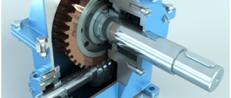
Worm gearboxes are one of the most common types of gearboxes. A worm gear is the engagement of a worm with a worm wheel. A worm is a screw with a thread cut on it, the profile is close to trapezoidal. Worm wheel is a helical gear with a special tooth profile. When the worm rotates, the threads move along its axis and push the teeth of the worm wheel in this direction. The axis of the worm crosses at right angles with the axis of the worm wheel, the distance between them determines the size of the gearbox. In Russian-made gearboxes, this size is an integral part of the gearbox designation and determines its overall size. For example, Ch-80 is a single-stage worm gearbox with an interaxial distance of 80 mm, and Ch-100, accordingly, has an interaxial distance of 100 mm.
Worm gear assembly steps
The assembly of a mechanism such as a gearbox is a labor-intensive operation performed during the manufacture of this device. The essence of the work is to adjust the relative position of the worm wheel and the worm.
The goal is to ensure that the worm axis coincides with the middle plane of the wheel. Also, the assembly of gearboxes requires ensuring a given level of tightness and the required size of gaps in the bearing assemblies. The process includes several technological transitions:
- the most accurate pressing of bearings directly onto the journals of the shaft of the adjustable elements, pressing of the cuffs into the appropriate holes in the cups or covers;
- the operation of assembling the worm shaft assembly with the mechanism body;
- installation of the wheel assembly directly in the housing.
If the gearbox has supports with tapered roller bearings, the operation of which depends on the correct set of shims used, then the second transition will include a number of works:
- One worm shaft bearing is taken. Its outer casing is installed in the hole in the device body.
- One cover with sealing gaskets is installed and secured to the device body.
- The worm shaft assembly is mounted into the hole in the body of the mechanism being assembled until it stops.
- Mount the outer race of the second bearing;
- Install the cover with the cuff into the end of the upper bearing race until it stops.
- Measure the size of the gap between the gearbox housing and the ends of the cover.
- Calculate where the contact patch is located (the wheel assembly is removed from the body, if required).
Then there is a process of adjusting the set of shims based on the actual position of the contact patch and the technical requirements.
The assembly operation is repeated in a similar way as many times as necessary to achieve the ideal mutual position of the adjustable elements.
Optimal conditions: the contact patch should pass exactly through the middle plane of the wheel, the direction of its shift towards the disengagement area is observed. Edge contact should be avoided.
Such assembly is in fact a piecemeal manual procedure that takes time and effort. Such work is unsuitable for large industries producing a significant number of devices. Therefore, large manufacturers have developed other methods of assembling mechanisms.
They use stocks based on the worm axis or the base end of the body (cutting teeth and metalworking of the body hole require especially close attention). Wheel assembly is complicated by the inevitability of careful control of two positions.
At the end of all operations, the contact patch is checked. Its location is clearly visible from the glare; it is also customary to use paint on the wheel teeth.
Successful tests are followed by testing of the motor reducer in accordance with the technical documentation and the expected volume of operation of the mechanism.
Advantages of worm gearboxes and drives built on them:
1. Since the input and output shafts of a worm gearbox are crossed, the drive based on it is usually better arranged in the machine, taking up less space compared to a spur gearbox (we are talking about gearboxes with equivalent gear ratios and transmitted power).
2. The gear ratio of the worm pair can reach 1:110 (in special cases - even more). Thus, the worm gear has a much greater potential for reducing speed and increasing torque compared to other types of gears. Achieving gear ratios of this order using cylindrical gears is only possible in a three-stage gearbox (or planetary gearbox). In a worm gear, only one stage can be used for this. This circumstance determines the relative simplicity and low cost of worm gearboxes compared to cylindrical gearboxes (again, we are talking about comparable gear ratios and transmitted powers). The flip side of this advantage, however, is a decrease in the efficiency of the worm gear as its gear ratio increases; for more information on this, see the “disadvantages” section.
3. The low transmission noise level, determined by the gearing features, allows the use of worm gearboxes in machines with high requirements for drive noiselessness. Here, however, we must not forget about the noise produced by engines and driven mechanisms.
4. Smooth running of the worm gear. Due to the peculiarities of the worm gearing, worm gearboxes have a smoother operation compared to cylindrical gearboxes.
5. A unique property of a worm gear is “self-braking” (another term for this phenomenon is “lack of reversibility”). Its essence is that if the drive shaft (worm) does not rotate, the driven shaft slows down and cannot be turned. This property begins to manifest itself at gear ratios of 35 and above. It would be more correct to talk here not about the gear ratio, but about the angle of lift of the worm, when decreasing, self-braking occurs at a certain moment. Full self-braking is achieved in a gear in which the angle of elevation of the worm helix is equal to or less than 3.5°. However, gearbox manufacturers do not always provide information about this parameter in their catalogs, and developers have to operate with gear ratios. The described property, depending on the area of application of the gearbox, can be both an advantage and a disadvantage. For example, it would be a design mistake to use a worm gear in the drive of, say, a seaming device, when filling which requires manually turning the reel with rolled sheet material, since a worm gear, even with a gear ratio of less than 25, is quite difficult to turn by the driven shaft. On the contrary, the use of a worm gear (with a large gear ratio of the worm pair) in the drive of the lift allows in many cases to avoid installing an additional braking device.
6. There are versions of worm gearboxes with a hollow output shaft. These gearbox options (also called “snap-on”) allow gearboxes to be mounted directly onto actuator shafts without the use of couplings or additional mechanical gears. This installation, in combination with the use of so-called “reaction rods” or flanged versions of the gearbox, simplifies the design and reduces the size of the drive:
The described advantage can be enjoyed not only by worm gearboxes, but also by other types of gearboxes, with the possible exception of coaxial cylindrical ones, where such an installation is impossible due to their design features. It should be noted here that sometimes the absence of a safety clutch between the output shaft of the gearbox and the shaft of the driven mechanism can lead to gearbox failure due to the application of an abnormal load to the output shaft, exceeding the rated output torque of the gearbox. In such cases, the designer’s task is either to ensure that there is no likelihood of such loads being applied, or to protect the drive from them, for example, using a coupling.
The above applies to a greater extent specifically to worm gearboxes due to their self-braking.
Worm gear assembly
Worm gears are used for small and medium powers, usually not exceeding 50 kW (Fig. 11).
Rice. 11. Worm gear: 1 – worm; 2 – worm wheel
Gearboxes with a worm gear can be with an upper, lateral and lower location of the worm relative to the worm wheel. The lower worm is usually used at a peripheral speed of υ≤4 m/s. The most common transmissions are with the Archimedean worm.
The assembly of the worm gear begins with checking the location of the axes of the gearbox holes.
The parallelism of the worm axis to the base surface of the gearbox base is checked (Fig. 12).
Rice. 12. Scheme for checking the accuracy of the location of holes in the worm gear housing: a – parallelism to the base; b – perpendicularity of the end surfaces of the hole axis
The worm gear housing is installed on the control plate on measuring tiles (Fig. 12, a). A control mandrel is inserted into the bores of the body under the worm supports. The parallelism of the ends of the control mandrel to the base of the gearbox is checked using a height gauge or an indicator at the ends of the control mandrel. Measurement accuracy – 0.05 mm.
To check the perpendicularity of the end surfaces of the gearbox to the hole axis (Fig. 12, b), a control mandrel is inserted into the bores under the worm supports, which has a fixed indicator on one side. The indicator touches the end surface of the gearbox, and on the other end of the mandrel rests against a square, which limits its axial movement. Based on the readings of the rotating indicator, one can judge the end runout of the plate to which the bearing cap will be adjacent. Measurement accuracy – 0.04 mm.
The control diagram for center distances is shown in Fig. 13, a. Control mandrels 2 and 3 are installed in the body.
Template 1 with three protrusions is installed on one of them. Based on the size of the gaps A and C between the protrusions of the template and the mandrel 3, the deviation of the interaxial distance in the vertical and horizontal planes is determined. Measurement accuracy – 0.06 mm.
Methods for controlling axle misalignment (crossing angle) are shown in Fig. 13, b.
Rice. 13. Scheme for checking the accuracy of the location of holes in the worm gear housing: a – center distance; b – axes locations
They check with mandrels and a template, as well as the center distance. The gap δ between the protrusions of the template is measured and the difference in readings is taken. The amount of misalignment across the wheel width is obtained by multiplying the resulting difference by the ratio of the dimensions of the wheel width to the distance between the protrusions.
A lever 4 with an indicator 5 is placed on the worm wheel shaft or mandrel. By bringing the indicator pin alternately to the left and right ends of the worm shaft or mandrel, the difference in deviation is used to judge the skew (crossing) of the axes. Measurement accuracy – 0.04 mm.
Disadvantages of worm gearboxes and drives built on them
1. The efficiency of a worm gearbox is lower than the efficiency of a cylindrical gearbox. Moreover, the efficiency decreases with increasing gear ratio. This entails energy losses - a factor that in the modern world cannot be discounted under any circumstances. For example, the efficiency of a Russian-made Ch-80 worm gearbox with a 1:80 gear ratio is 58%. The remaining 42% are losses due to irreversible energy dissipation. This disadvantage is due to the increased sliding friction of the worm turns on the teeth of the worm wheel compared to other types of gears. In this sense, a worm gear is similar to a “sliding screw-nut” gear, which is also not characterized by high efficiency. During the running-in period under load for 200...250 hours, the efficiency can be 90% of the nominal.
Lecture No. 6. Worm gears (WG)
Questions presented in the lecture:
1. Definition, classification of emergency situations.
2. Geometry, kinematics and dynamics of emergency situations.
3. Materials and manufacturing of emergency equipment.
| Definition and classification of emergency situations. |
The previous lectures discussed the design and parameters of gears with some types of gears. In these gears, the moving parts are gears mounted on rotating shafts. worm gears - have become widespread in technology.
(mechanisms for tensioning the tracks of infantry fighting vehicles and tanks, the drive of the BTR-80 winch, the main gears of some heavy trucks).
A worm gear is a transmission in which two moving links, a worm and a worm wheel, together form a higher gear-screw kinematic pair , and with the third, fixed link, lower rotational kinematic pairs.
| Rice. 6.1. Worm gear: 1 – worm; 2 – worm wheel. |
As follows from the definition, a worm gear has the properties of both gear (the worm wheel carries a toothed rim on its rim) and helical (the worm is shaped like a screw) gears. A worm gear, like a screw gear, is characterized by relatively high sliding speeds of the worm turns along the teeth of the worm wheel.
Advantages of worm gears: 1) compactness and relatively low weight of the structure; 2) the possibility of obtaining large gear ratios in one stage - standard gears u £ 80 , special ones - u ³ 300 ; 3) high smoothness and kinematic accuracy; 4) low noise and vibration levels; 5) self-braking during reverse transmission of motion, that is, the impossibility of transmitting motion in the opposite direction - from the driven worm wheel to the driving worm.
The disadvantages of worm gears are due to high sliding speeds
turns of the worm along the teeth of the worm wheel, as well as significant axial forces acting on the transmission shafts.
Disadvantages of worm gears: 1) Low efficiency and high heat generation; 2) increased wear and reduced service life; 3) a tendency to jam, which necessitates the use of special anti-friction materials for the manufacture of the worm wheel gear and special types of lubricant with anti-seize additives.
Worm gear classification:
1. in the direction of the worm’s turn line –
1.1. rights
(when observing from the end of the worm and rotating it clockwise, the worm screws into space and moves away from the observer);
1.2. left
(when observing from the end of the worm and rotating it clockwise, the worm twists out of space - it goes towards the observer);
2. by the number of worm passes –
2.1. with a single-thread worm having one ridge located along a helical line superimposed on the dividing cylinder of the worm;
2.2. with a two-, three-, four-, multi-threaded worm, having, respectively, 2, 3, 4 or more identical ridges located along a helical line superimposed on the dividing cylinder of the worm;
3. according to the shape of the dividing surface of the worm -
3.1. with cylindrical
a worm (the generatrix of the dividing surface is a straight line);
3.2. with globoid
a worm (the generatrix of the dividing surface is an arc of a circle coinciding with the circumference of the dividing surface of the worm wheel);
4. by the position of the worm relative to the worm wheel -
4.1. with the bottom
worm location;
4.2. with top
worm location;
4.3. with side
worm location;
5. according to the spatial position of the worm wheel shaft -
5.1. with horizontal
worm wheel shaft;
|
5.2. with vertical
worm wheel shaft;
6. according to the shape of the side (working) surface of the worm coil (Fig. 6.2) –
6.1. with an Archimedean worm, the lateral surface of its turns is outlined by a straight line in the longitudinal-diametrical section (designated ZA);
6.2. with a convolute worm, the lateral surface of its turns is outlined by a straight line in a section normal to the direction of the turns (denoted by ZN);
6.3. with an involute worm, the lateral surface of its turns in the longitudinal-diametrical section is outlined by an involute (designated ZI).
An involute worm is equivalent to a cylindrical involute helical gear with a number of teeth equal to the number of worm runs.
The shape of the side surface of the worm has little effect on the performance of the worm gear and is mainly associated with the selected worm manufacturing technology (Fig. 6.2).
| Geometry, kinematics and dynamics of emergency situations. |
|
Let's consider the geometry, kinematics and dynamics of a worm gear using the example of a gear with an Archimedean worm.
The geometric characteristics of a worm gear are interconnected by relationships that are in many ways similar to the relationships of gears.
The main standardized parameter of a worm gear is the module m (measured in mm), axial for the worm and circumferential (face) for the worm wheel. Since the pitch diameter of the worm cannot be associated with the number of its starts z1 (the turns of the worm are cut along its axis, and not along the circumference, like a gear), to determine the pitch diameter of the worm, a special coefficient of worm diameter q , showing the number of modules that fit into the pitch diameter .
The geometry of the worm wheel crown also has its own characteristics. Due to the fact that the generatrix of the pitch surface of the worm wheel rim (Fig. 6.4) has an arcuate shape and, therefore, at different points there are different distances from the axis of rotation of the wheel, all main dimensional indicators (pitch diameter, tooth height, etc.) are measured in the middle plane passing through the geometric axis of the worm.
Taking into account the above, the module with the pitch diameters of the worm (Fig. 6.3) and the worm wheel (Fig. 6.4) is related by the relations
. (6.1)
The distance measured between the same surfaces of two adjacent worm cutting ridges is called the calculated worm cutting step
.
The calculated cutting step of the worm (dimension p in Fig. 6.3) is related to the module of the worm gearing by a ratio similar to that for gearing:
. (6.2)
The distance measured between the same surfaces of two adjacent ridges belonging to the common helical cutting line of the worm is called the stroke of the worm.
.
From the definition it follows that the design step p and the turn stroke pz are related by the relation
| Rice. 6.4. Worm wheel ring parameters |
. (6.3)
The height of the heads of the worm turns and the teeth of the worm wheel, as in gearing, is equal to the engagement module ( ha1 = ha2 = m ), and the height of the legs, in order to eliminate the possibility of the tooth head sticking into the bottom of the cavity, as in bevel gears, is 20% greater than the module gearing ( hf1 = hf2 = 1.2m ). Then the diameter of the tops of the turns (outer diameter) of the worm da1 (Fig. 6.3) and the diameter of the tops of the teeth of the worm wheel da2 (Fig. 6.4) can be found from the expressions
; (6.4)
and the diameter of the cavities of the turns (inner diameter) of the worm df1 (Fig. 6.3) and the diameter of the cavities of the teeth of the worm wheel df2 (Fig. 6.4) - according to the expressions
. (6.5)
a measured in the plane of the axial section between the tangent to the lateral surface of the worm turns and the normal to the axis of its rotation for Archimedean worms is a constant value, standardized and equal to 20°. Consequently, the angle between two tangents to the opposite lateral surfaces of one turn (the angle of the ridge) is 2a or 40°.
The length of the cut part of the worm b1 (Fig. 6.3) depends on the number of its passes and is selected according to the empirical formula
when the number of worm turns is z1 = 1 and z1 = 2; (6.6)
and with the number of turns of the worm z1 = 4 [3] . (6.7)
The ratio of the stroke of the turn to the length of the pitch circle of the worm is the value of the tangent of the angle of elevation g of the helical cutting line of the worm
(6.8)
A feature of the worm wheel (Fig. 6.4) is that the diameter of the tops of the teeth da2 is not its largest diameter. The maximum diameter of the worm wheel daM2 is set somewhat arbitrarily. An increase in this diameter helps to increase the area of the contact surface of the wheel teeth, and, consequently, to reduce the contact stresses on this surface that arise during the operation of the gear. However, its excessive increase leads to a sharpening of the peripheral sections of the tooth and their exclusion from the transmission of work loads due to increased flexibility. Therefore, the maximum diameter of the worm wheel teeth daM2 is limited from above by the ratio
. (6.9)
The width of the worm wheel b2 is selected according to a standard range of sizes. In this case, the size b2 must satisfy the relation
when the number of worm turns is z1 = 1 and z1 = 2; (6.10)
and with the number of turns of the worm z1 = 4. (6.11)
When performing strength calculations of a worm gear, there is a need to know the conventional angle 2 d of coverage of the worm turns by the teeth of the worm wheel
(Fig. 6.4). This angle is determined by the points of intersection of the side (end) surfaces of the worm wheel with a conventional circle, the diameter of which is equal to , therefore
. (6.12)
The center distance for an unbiased worm gear is determined by the formula
. (6.13)
| Rice. 6.5. Worm gear speed diagram |
In a worm gear, in contrast to a gear, the peripheral speeds of the turns of the worm v1 and the teeth of the worm wheel v2 (Fig. 6.5) are different both in magnitude and direction. The turns of the worm, when rotating, receive speed v1 , directed tangentially to its initial circle, and the teeth of the worm wheel move together with the helical line parallel to the worm axis at speed v2 . For one revolution of the worm, the worm wheel will rotate through an angle covering the number of teeth of the wheel equal to the number of runs of the worm. These simple observations allow us to write the following relationship to calculate the gear ratio of a worm gear
. (6.14)
The geometric sum of the speeds v1 and v2 is equal to the speed of the relative movement of the worm turns in relation to the gear teeth. The velocity plan constructed for the gearing allows us to write down the following dependencies
. (6.15)
Thus, the speed of sliding of the worm turns along the teeth of the worm wheel is the highest compared to the tangential speeds of movement of the worm turns and the teeth of the worm wheel.
The efficiency hz of a worm gear can be calculated as the efficiency of a screw kinematic pair:
with the leading worm; (6.16)
and with a driving worm wheel; (6.17)
where is the friction angle in the worm kinematic pair, and f is the friction coefficient for the materials of the worm turns and the worm wheel gear.
When g £ rhzo = 0, the transmission of motion from the worm wheel to the worm becomes impossible - self-braking occurs. The property of self-braking of reverse movement is widely used in winches and lifting mechanisms. However, it should be noted that such self-braking mechanisms have low efficiency even in the forward direction of transmission.
| Rice. 6.6. Forces in the worm gear |
In a worm gear, the force Fn acting on the side of the worm is, as a rule, perceived not by one, but by several teeth. However, just like in gears, when performing calculations, it is customary to place this force in the engagement pole (Fig. 6.6, a). This force is not difficult to decompose according to the parallelogram rule into three mutually perpendicular components Ft1 , Fr1 and Fa1 . Next, according to Newton’s third law, we establish that (Fig. 6.6, b) Ft2 = Fa1 , Fa2 = Ft1 and Fr2 = Fr1 .
The tangential forces on the worm and worm wheel are most conveniently calculated through the torques on the corresponding shafts, then
(6.18)
And . (6.19)
Radial forces on worm and wheel
. (6.20)
| Materials and production of state of emergency. |
The worm turns and the worm gear ring must have sufficient strength and form an antifriction pair with high wear resistance and resistance to seizing under conditions of high sliding speeds with significant normal forces between the contacting surfaces.
For the manufacture of worms, all three types of steels common in mechanical engineering are used:
1. High-quality medium-carbon steels of grades 40, 45, 50. Low-responsibility worms are made from them. Before machining, the workpiece is subjected to improving heat treatment (HRСе £ 36). The worm is sharpened on a lathe, followed by manual or mechanical grinding and polishing of the working surfaces of the turns.
2. Medium-carbon alloy steels of grades 40Х, 45Х, 40ХН, 40ХНМА, 35ХГСА. Worms of critical gears are made from these steels. The part is subjected to improving heat treatment (HRCe £ 45) after pre-processing on a lathe. After heat treatment, the working surfaces of the coils are ground on special worm grinding machines or on a lathe using a special grinding head.
3. Low- and medium-carbon alloy steels of grades 20Х, 12ХН3А, 25ХГТ, 38ХМУА. Worms of highly loaded gears operating in reverse mode are made from these steels. The part, manufactured with a minimum allowance for final processing, is subjected to surface chemical-thermal treatment (cementation, nitriding, etc.) to a depth of 0.8 mm, after which it is hardened to a high surface hardness (HRCe 55...65). The working surface of the worm turns is ground and polished (sometimes shaving).
The gear rims of worm wheels are most often made by casting from bronze or cast iron.
Cast iron crown
(gray cast iron SCh15, SCh20 or malleable cast iron KCh15, KCh20) can be cast in one piece with the rim of the worm wheel when casting the latter.
Such wheels are used, as a rule, in low-speed open and closed gears ( vs £ 2 m/s).
At average sliding speeds (2 < vs -free bronzes are used for the manufacture of worm wheel gears
and brass. Most often, iron-aluminum casting bronzes (Br A9Zh3L, Br A10Zh4N4L) are used for this purpose. These bronzes have high mechanical strength, but have reduced anti-seize properties, so they are used in conjunction with worms that have a ground and polished working surface of high-hardness turns (HRC ³ 45).
In gears with high sliding speeds (5 < vs £ 25 m/s), the worm gears are made of tin bronze
(Br O10F1, Br O10N1F1). These bronzes have reduced strength compared to tin-free bronzes, but have good anti-seize properties.
Bronze rims of worm wheels are usually made by casting in the ground, in a chill mold (metal mold) or by centrifugal casting. At the same time, castings obtained by centrifugal casting have the best strength characteristics.
The blank for the gear rim can be cast directly on the rim of the worm wheel, or cast as a separate part, then the rim is mounted and secured against both the possibility of rotation and longitudinal displacement.
In order to select a material for the manufacture of a worm wheel gear, the previously expected sliding speed vs can be determined by the empirical expression
, (6.21)
where vs – sliding speed, m/s; n1 – worm rotation speed, min-1; T2 – torque on the worm wheel, N×m.
This lecture provides basic information on the design, kinematics and dynamics of worm gears, presents the main materials used for the manufacture of worms and worm gears, as well as some technological information on their manufacture. Issues related to the design and verification calculations of worm gears will be discussed further.
| Questions for self-control: |
1. Name the main features of a worm gear.
2. Why are worm gears called helical gears?
3. Name the advantages of worm gears.
4. What are the disadvantages of worm gears, what causes them?
5. Name the main classification characteristics of worm gears.
6. What are the differences between involute, convolute and Archimedean worms?
7. What is the module in a worm gear and how is it related to the initial (pitch) diameter of the worm?
8. What sizes of a worm are called the cutting pitch and the helix stroke; which worms, in your opinion, have these two sizes the same?
9. Express the height of the worm threads and worm wheel teeth in terms of the worm gear module.
10. Show the relationship between the diameters of the cavities and the diameters of the projections of the worm turns and the teeth of the worm wheel.
11. How to determine the angle of elevation of the helix of the worm turns?
12. How are the maximum diameter and width of the worm gear ring gear determined?
13. What is called the conventional angle of coverage of the worm turns by the teeth of the worm wheel; How is its value related to other geometric transmission parameters?
14. Is it possible to express the gear ratio of a worm gear through the initial diameters of the moving links, similar to a gear drive?
15. What indicator is called the sliding speed in a worm gear and how is it related to the speeds of movement of the worm turns and the teeth of the worm wheel?
16. What does the efficiency of a worm gear depend on?
17. What is meant by self-braking of a worm gear?
18. Name the components of the force acting on the turns of the worm in mesh, and the equal components of the force acting on the teeth of the worm wheel.
19. Why are gear elements made, as a rule, from the same
20. materials, and the worm is made of different ones?
21. What are the main criteria for a worm gear that influence the choice of material for making the worm gear ring?
é
Applications of Worm Gearboxes
The range of applications is extremely wide. Conveyors, conveyors, lifts, pumps, mixers, gate drives, metalworking machines, including for milling work. Where a budget solution is required to reduce the drive speed and increase the torque in the absence of significant shock loads and low frequency of switching on, install a worm gearbox. However, this is still too categorical a statement. Without claiming absolute infallibility against the truth, I will still try to formulate basic recommendations for the use of worm gearboxes:
1. If self-braking is not required and the gear ratio must be greater than 25, use helical-worm gearboxes. The efficiency of such a gearbox will be higher due to a decrease in the gear ratio at the worm stage. Accordingly, there will be savings in energy costs and an increase in service life.
2. Do not install worm gearboxes in drive mechanisms that are subject to shock loads. During long-term operation with shocks, the worm gearbox may overheat and its service life will sharply decrease. The author of these lines witnessed the boiling of oil in a gearbox transmitting a power of 4 kW after several hours of its operation as a drive for a drum of a buffing device, which was subjected to periodic shock loads from a knife cutting off the tread blocks of worn tires.
3. The installation diagram of the gearbox in space is of great importance. The basic and most recommended scheme for transmission lubrication is the scheme when the worm axis is at the bottom and the wheel axis is at the top:
A different orientation in space is possible; when ordering, carefully consider the correspondence of the designation of the gearbox layout with reality! If there is a discrepancy, oil may leak from the gearbox, the worm may run “dry” or, conversely, be completely immersed in oil. All this leads to a sharp reduction in resources. With an upper worm position, technical literature recommends reducing the rated output torque by 20%.
4. The use of a reaction rod or flange mounting is preferable to installing a gearbox on feet.
5. I do not recommend using worm gears in positioning systems. The backlash present in the transmission can negatively affect the accuracy (here, of course, everything depends on specific conditions - if the output shaft is connected, for example, to a lead screw that has a small pitch, and the required positioning accuracy of the nut is ±1 mm, a worm gearbox is quite suitable).
6. When choosing the type of gearbox in relation to a worm gearbox, it is always necessary to be aware of the possibility of self-braking and everything that follows from this property. Do not install a worm gearbox to drive a trolley wheel set if it will sometimes need to be rolled by hand. It will be hard to ride.
7. Before putting a new gearbox into operation under load, it is recommended to run it in idle mode (without operating load or with a reduced load) for 15...20 hours to run-in the rubbing surfaces.
8. Worm gearboxes generally require thicker lubrication than other types of gearboxes.
Worms are divided into types according to the following characteristics:
- by number of thread starts: single-start, multi-start
- in the direction of thread cutting: right, left
- according to the shape of the screw on which the thread is cut: cylindrical, globoid
- according to the shape of the thread profile: with a convolute profile, with an Archimedean profile, with an involute profile
- Gears are divided into types according to the following characteristics:
- by wheel type: wheel itself, gear sector, degenerate sector
- according to the profile of the teeth: straight, concave, roller (a rotating roller is used instead of teeth
Worm gearboxes with a built-in motor are called worm gearmotors. In gearboxes, the motor shaft is most often located at right angles to the movable one. The layout of the worm gearbox is selected based on the specific requirements for the devices. The engine can be located either on top of the driven wheel, or below and on the side. When positioned sideways, the engine is installed vertically. Due to the vertical location, the process of lubrication of the shaft bearings, as well as cleaning of external elements, is complicated.
Various technologies are used to increase the gear ratio, but the most effective is the use of a larger number of stages.
To soften friction forces and increase resistance to seizing, special viscous lubricants or oils are used. At low rotation speeds, lubrication is carried out using special oil baths or using special devices that spray lubricant into areas of high friction. For worm gearboxes, the rotation speed of which is high, the use of baths is impractical, and forced lubrication with cooled lubricants is used.
The main advantages of a worm gearbox over gears are that the initial contact of the links occurs not at a point, but along a line. Also, the input and output shafts can cross at different angles, but most often this angle is 90 degrees. Also, a worm gear takes up much less space than a toothed gear with the same large gear ratio.
Operation after installation of the gearmotor
The set of documents includes two passports - the mechanism itself and the lubricant. They are needed at all stages of operation. In the lubricant passport, the manufacturer enters information about the frequency of replacement of the composition, the rules for its selection and refilling methods.
The gearbox passport contains recommendations for operation, installation, and first start-up. The following data is entered into it:
- based on inspection results (checking distortions and displacements);
- after an audit of security programs at the enterprise;
- based on the results of repair work (adjustment, elimination of backlash, overhaul);
- about TO.
Every employee who may be at the installation site of a geared motor must know the minimum set of rules for safe operation. What does this include:
- control of hatches (always closed);
- preventing dust from entering the device body;
- prevention of accidents due to foreign objects getting into moving parts (fasteners, tools, personal protective equipment cannot be placed on the equipment during work, repair, inspection, maintenance).
Use of lubricants
The recommended type of lubricant must be indicated in the lubricant data sheet.
Lubricant replacement for most gearboxes is carried out 2-4 times a year during scheduled maintenance. After 2 weeks of operation after installing the gearbox, it is necessary to remove the primary wear products of metal moving elements from its oil. This is done like this:
- the gear motor stops;
- the composition is completely merged;
- Gearbox oil is passed through a filter;
- After filtration, the composition is poured back into the container.
An important parameter is the pour point of the lubricant composition; it should not be equal to or exceed the statistical ambient temperature. For bevel-helical gearboxes it is usually set at 60 degrees (oil bath).
Types of worm gearboxes
Worm gearboxes can vary significantly depending on the application of the mechanism.
The main differences that can be used in the design:
- Different number of visits;
- Part material;
- Thread direction;
- Thread profile;
- Types of screw used.
These differences may be present in various combinations. The engineer decides what types of worm gearboxes to use at the design and development stage of devices and mechanisms that use these types of torque transmission.
Procedure for selecting a worm gearbox
Among the advantages of this mechanism is the reasonable price of the worm gearbox . But even taking this into account, the selection must be very careful. In order to buy equipment that will optimally fit into the technical equipment program used, you need to understand the basic parameters for choosing a worm gearbox. This system for calculating parameters for determining price contains the following characteristics:
- gear ratio;
- efficiency;
- number of steps;
- planned launch time;
- overall dimensions of the structure.
Determination of gear ratio
The selection of a worm gearbox begins with the calculation of the gear ratio - the ratio of the teeth of the driven gear to the number of teeth of the drive worm. The multiplicity of increase in torque when the worm moves depends on this.
To calculate the gear ratio (required) in order to correctly select a worm gearbox, a formula of the form is used:
Where:
- N in. – these are the de facto revolutions of the electric motor input shaft (according to the passport, quantity per minute);
- N out. – the required number of revolutions of the low-speed output shaft per minute.
Results must be rounded. After which you can buy a model, guided by the table of gear ratios for different variations of mechanisms.
Calculation of the number of steps
Calculation of the gear ratio is also key when determining the required number of steps. To accomplish the last task, it is necessary to select a system according to the obtained relationship from the table below.
| Worm gear selection | Gear ratios |
| single stage | 8–80 |
| two-stage | 100–4000 |
Selection of worm gear by size
Competent selection of a worm gearbox based on dimensional parameters requires matching the power parameters and engine speed with the type of drive mechanism. To decide which size you need to buy, use the formula:
Where:
- P – performance of the electric motor used, taken in kW;
- U is the calculated gear ratio;
- N – efficiency, according to technical characteristics and calculation results;
- K – utilization/operation coefficient, taken depending on the operating conditions of the worm gearbox , according to the table (it is presented below);
- N in. – nameplate number of engine revolutions.
| Mode of use (according to GOST 21354-87, as well as GosTechNadzor standards) | PV (%) | K | |
| 0 | Continuous | 100 | 0,7 |
| I | Heavy | >63 | 0,8 |
| II | Average | <63 | 1,0 |
| III | Average normal | 40 | 1,0 |
| IV | Easy | 25 | 1,2 |
| V | Particularly light | 16 | 1,5 |
| Episodic (load without impacts, plus work two hours a day, with four starts per hour) | 25 | 1,8 | |
Duration of operation
The switching time is calculated as follows:
Where:
- T is the operating period taken in minutes per hour of work based on the average.
- The result is determined as a percentage.
Important condition: the resulting torque must not exceed the rated torque. The latter is indicated in the passport (technical characteristics of the worm gearbox ). This is necessary for long-term operation of the mechanism shafts (to avoid differences between the loads applied de facto and those provided for in the passport).
Worm Gear Design
It is almost impossible to make a worm gearbox with your own hands. The calculation of the worm gear must be carried out by a qualified specialist. When the drawing is made, all parts according to it are made only from materials of proper quality, otherwise the gear mechanism may fail after a short period of work. The assembly of the worm gearbox should also be carried out by an experienced craftsman. Failure to comply with this rule can significantly reduce the service life of the part, because in addition to the correct installation of the shafts, careful adjustment of the worm mechanism will be required.
If it is necessary to use a worm gear in order to install a homemade torque transmission mechanism, then in this case it is better to use ready-made used products from equipment that uses a similar type of torque transmission. In the case when independent development of new devices that will be patented is carried out, the design of a worm gearbox should be ordered from a design bureau engaged in such developments.
Where to buy a worm gearbox
If you are planning to buy a worm gearbox for the long term at a reasonable price, we have something to offer you. PTC "Privod" has been supplying this equipment throughout Russia and the CIS countries for many years.
We offer only highly reliable, high-quality gearboxes and geared motors at effective manufacturer prices with long-term service guarantees.
We provide full support for your order - from assistance in constructing a system of requirements to selecting a worm gearbox that meets the stated operating conditions. For your convenience, we have created an electronic catalog of worm gearboxes - you can view it on our website. For advice on any issue, call us or write to us by email (the details in the contacts section are relevant).
Principle of operation
The basis of the entire transmission mechanism is a worm-shaped drive screw, in honor of which these types of gearboxes got their name. The worm screw interacts with a gear whose axial shaft is located at a right angle. As a result of this coupling, a high rotation speed of the input shaft with low torque is transformed into rotation of the output shaft with a low frequency but much greater force. The layout of the worm gearbox can be different. If the worm gear shaft rotates at a speed below 5 m/s, then the worm is located at the bottom, if the speed is higher, then a gearbox with an upper worm is installed.
Most mechanisms of this type are used with a single gear stage, but sometimes a two-stage worm gearbox can be used to control the ratio.
If the shaft rotation speed is more than 10 m/s, the bearings and hypoid gears must be lubricated under pressure. If the engine is low-speed, then natural oil circulation when the gear rotates is sufficient.
Oil for worm gearboxes must be of high viscosity, otherwise the wear process of the most loaded parts of the gearbox will be significantly accelerated.
Steering
It is used in cars not only in axles, but also in the steering system. In fact, the liquid steering gear is the oldest system that has gone through many changes, but its technical principle has remained the same.
The steering gear in a car is used to make it easier to turn the steering wheel, even in a car without power steering.
The steering gearbox has a number of advantages, the main one being the large energy transfer ratio. We can say that the advantages include the low noise of the gearbox and smooth operation. The steering gear also has disadvantages, the main of which is rapid wear of the chain mechanism and excessive heat generation. The drive for the steering energy converter is the steering wheel.
Gearbox lubrication system
Each such vehicle unit has a lubrication system. Oil is supplied under pressure to the bearings and chain mechanism. In addition to its direct responsibility, the lubrication system cools and removes excess wear elements from the gearbox housing, which can render the chain gears unusable. These elements leave the system with the oil and are retained by the filter.
To prevent oil from leaking out of the gearbox housing, special seals are required. Special oil seals in the car are not only in this system. These seals are found wherever a seal is required. In order for the seals to create a tight seal, the seals must be installed correctly. Replacing oil seals is the same complex procedure as repairing a gearbox. The first reason that oil seals need to be replaced is a trace of oil on the housing.