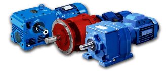
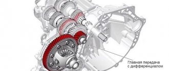
Worm gearboxes belong to the class of the most common gear mechanisms.
Due to their optimal price, they are in demand both for equipping household appliances and for completing heavy industrial equipment (such gears are indispensable in the mechanisms of conveyor systems). The functions of a worm drive come down to 2 basic points - converting the moment of force (increasing torque) and simultaneous control (adjustment) of the angular speeds of the rotational movement of the engine elements. Pros: price, ability to reduce gears and self-braking. The device operates in the range from 20 to 1 to 300 to 1 or more.
Operating principle
The main feature of the worm system - self-braking - makes it especially relevant for completing production and industrial (professional) equipment. Due to self-braking, the gear begins to move under the influence of the screw (worm), but it itself does not rotate the screw.
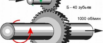
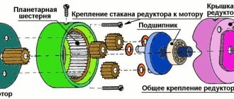
The principle is based on the interaction of two functional elements:
- The leading worm receives rotational energy from the motor and converts it. It has the shape of a screw.
- The driven wheel receives the converted energy from the worm and “spins” the output shaft.
Procedure for selecting a worm gearbox
Among the advantages of this mechanism is the reasonable price of the worm gearbox . But even taking this into account, the selection must be very careful. In order to buy equipment that will optimally fit into the technical equipment program used, you need to understand the basic parameters for choosing a worm gearbox. This system for calculating parameters for determining price contains the following characteristics:
- gear ratio;
- efficiency;
- number of steps;
- planned launch time;
- overall dimensions of the structure.
Determination of gear ratio
The selection of a worm gearbox begins with the calculation of the gear ratio - the ratio of the teeth of the driven gear to the number of teeth of the drive worm. The multiplicity of increase in torque when the worm moves depends on this.
To calculate the gear ratio (required) in order to correctly select a worm gearbox, a formula of the form is used:
Where:
- N in. – these are the de facto revolutions of the electric motor input shaft (according to the passport, quantity per minute);
- N out. – the required number of revolutions of the low-speed output shaft per minute.
Results must be rounded. After which you can buy a model, guided by the table of gear ratios for different variations of mechanisms.
Calculation of the number of steps
Calculation of the gear ratio is also key when determining the required number of steps. To accomplish the last task, it is necessary to select a system according to the obtained relationship from the table below.
| Worm gear selection | Gear ratios |
| single stage | 8–80 |
| two-stage | 100–4000 |
Selection of worm gear by size
Competent selection of a worm gearbox based on dimensional parameters requires matching the power parameters and engine speed with the type of drive mechanism. To decide which size you need to buy, use the formula:
Where:
- P – performance of the electric motor used, taken in kW;
- U is the calculated gear ratio;
- N – efficiency, according to technical characteristics and calculation results;
- K – utilization/operation coefficient, taken depending on the operating conditions of the worm gearbox , according to the table (it is presented below);
- N in. – nameplate number of engine revolutions.
| Mode of use (according to GOST 21354-87, as well as GosTechNadzor standards) | PV (%) | K | |
| 0 | Continuous | 100 | 0,7 |
| I | Heavy | >63 | 0,8 |
| II | Average | <63 | 1,0 |
| III | Average normal | 40 | 1,0 |
| IV | Easy | 25 | 1,2 |
| V | Particularly light | 16 | 1,5 |
| Episodic (load without impacts, plus work two hours a day, with four starts per hour) | 25 | 1,8 | |
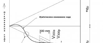
Duration of operation
The switching time is calculated as follows:
Where:
- T is the operating period taken in minutes per hour of work based on the average.
- The result is determined as a percentage.
Important condition: the resulting torque must not exceed the rated torque. The latter is indicated in the passport (technical characteristics of the worm gearbox ). This is necessary for long-term operation of the mechanism shafts (to avoid differences between the loads applied de facto and those provided for in the passport).
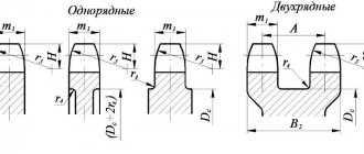
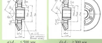
126a. Values of the coefficients of the parameters of the turns of the original worm
| Odds | Designation | Numerical value or formula for worms | ||
| ZA, ZK, ZN | ZL | ZT | ||
| Heights of coil | h1* | 2.0+s1* | ||
| Coil head heights | ha1* | 1,0 | ||
| Heights of the coil leg | hf1* | 1.0 +s1* | ||
| Boundary coil height, not less | hl1* | 2,0 | ||
| Entry depths | hw* | 2,0 | ||
| Radial clearance at the surface of the depressions: worm | c1* | 0,2 | ||
| worm wheel | c2* | 0,2 | ||
| Design coil thickness | s* | 0.5π | 0.45π | 0.35π |
| Radius of curvature of the transition curve | Pf1* | 0,3 | 0,2 | |
| Radius of the generating arc of the grinding wheel circle | P0* | — | 4,8-6,0 | |
Notes:
1. It is allowed to change the coefficient of design thickness for worms: ZA, ZL, ZK and ZN in the range from 0.4 to 0.5π; ZT ranges from 0.3π to 0.38π.
2. In justified cases, it is allowed to change the coefficient of radial clearance at the surface of the worm wheel cavities in the range from 0.15 to 0.3.
3. For involute worms and worms with a pitch angle of at least 26.565°, take c1 = 0.2cosγ.
4. Mandatory thinning of the calculated thickness of the coil of the initial worm Δs in comparison with the calculated thickness of the coil of the initial producing worm is not regulated.
5. The edge of the head of the coil of the original worm is blunted with a radius pk = 0.05m or a chamfer of the appropriate size.
6. The value of the radius coefficient of the generating arc of the circle of the grinding wheel P0* is taken in the range from 4.8 to 6.0 under the condition that there is no cutting of the worm wheel tooth.
Main selection criteria
One of the main technical parameters of the drive mechanism, which plays the main role in the gearbox selection technique , is efficiency (also known as efficiency or efficiency). Unlike dimensional characteristics or performance, it is not a constant value and can vary depending on:
- on the size of the product;
- class of lubricant used;
- equipment speeds;
- gear ratio;
- condition of the drive mechanism (completely new, after the first run-in, after incomplete run-in, etc.).
It is installed for each model and is calculated taking into account the complete running-in of the system shafts, the use of oil recommended by the manufacturer, and the application of loads not exceeding the standards specified in the passport. For the new model, a reduction of 2–12% relative to the passport data is allowed (more details in the table below).
| Number of worm visits | Gear ratio | Decrease in efficiency |
| Single-set worm | i = more than 30:1 | Approx. 12% |
| Double-set worm | i = 26-20-15:1 | Approx. 6% |
| Four-set worm | i = 13-10-7.5:1 | Approx. 3% |
| Six-set worm | i = 5:1 | Approx. 2% |
Starting efficiency
To avoid distorted data on the efficiency of the worm, the concept of starting efficiency is included in a separate paragraph. Thus, this coefficient is always lower than the working one due to the lack of an established (developed) sliding process and increased drive torque during the start of the movement of the working shafts.
Factors that determine the starting coefficient: oil, coil inclination angle, run-in stage completed. Upon completion of the run-in, this indicator should correspond to the data in the table.
| Number of worm visits | Gear ratio | ηA |
| Single-set worm | i = 83-63:1 | 0,30 — 0,40 |
| Single-set worm | i = 53-40-30:1 | 0,40 — 0,50 |
| Double-set worm | i = 26-20-15:1 | 0,56 — 0,65 |
| Four-set worm | i = 13-10-7.5:1 | 0,68 — 0,75 |
| Six-set worm | i = 5:1 | 0,74 — 0,82 |
For the new mechanism, the efficiency will be lower. If the shafts have been inoperative for a long time, at the first start after idle time its coefficient will rush to the lower limit.
Self-braking effect
A mechanism with a self-braking effect cannot be activated by the worm.
If there is a need for such an option, the choice of worm gear should be based on the rated efficiency. For a working device with a self-braking effect, it should not exceed 50%. The selection of a worm gearbox, taking into account the self-braking factor, must be professional and individual. To determine the need for your equipment for such an effect, please contact our specialists. Based on the description of operating conditions and requirements, they will help you choose the appropriate option (with self-braking, without self-braking).
Lubrication
Lubricant (synthetic) is poured in the production workshop. This is necessary to monitor and check efficiency, as well as to avoid filling errors that could lead to a reduction in service life (and the need to buy new parts).
If the specified loads are observed, maintenance of the drive device, filled with oil at the manufacturer’s factory, is not required. If operating conditions are close to extreme, or productivity requirements are increased, then the lubricant must be changed every 15 thousand hours worked. It is worth considering the following:
- Type 040 mechanisms do not have ventilation holes;
- models 050–100 are equipped with 1 hole (for oil and breather);
- versions from 125 are equipped with lubrication control systems and drain plugs.
C,
the sliding speed of the worm v'c (in SI units) or v (in previous units) is determined by the formula (in later methods the formula is different): v'c=m·wch·[q2 + zch2]½ / 2, [m /With];
vc =m·π·nч·[q2+zч2]½ / [1000·30], [m/s]; where wч(nч) is the angular speed of engagement, rad/s (rpm). To convert from rpm (rotation speed) to rad/s (angular velocity), we use the following relationship: wch = 2·π·nч/60 If we use this conversion formula to convert the calculation formula in new units, we obtain the following expression for calculating speed slip: vc =m·π·nч·[q2+zч2]½ / [1000·60], [m/s], We have some differences from the calculation formula in old units... Let's bring the formula for determining contact strength to a form convenient for us. We calculate the gear drive in new units, substituting power in W, module in mm, instead of angular velocity [rad/s] - rotation frequency [rpm]. So, let’s transform for substitution into the formula - m/1000 [m],2·π·nк/60 [rad/s]. Since we have reference tables for permissible voltages in kg/mm2, then, using the equality 9.8 W = 1 kg m/s, we convert the resulting expression into kg/mm2. Then the formula for calculating the gear for contact strength will take the form: τс = [(В/zк)2·Nк·K·8·60·10003 / (2·π·nк·m3·q)]½ / [9.8 ·10002] s, When
choosing a material, the sliding speed vc of the worm relative to the wheel and the load are taken into account.
At high speeds (5 ÷ 25 m/s), a combination of a steel hardened, ground and polished worm with a bronze wheel rim is chosen (the center of the wheel is usually made of cast iron). For heavy loads, worms are made from steel grades 45 and 50 according to GOST 1050, from steel grades 35 according to GOST 1050 and St. 3 according to GOST 380. Wheel crowns at high speeds (5 ÷ 30 m/s) are made of bronze: in accordance with previously used designations of the material grade - tin - Br.OF 10-1 and tin-nickel Br.ONF 11-4-3; taking into account the new designations - tin-phosphorus bronzes BrO10N1F1, BrO10F1, tin-zinc bronze BrO5Ts5S5. The higher Vc and the duration of transmission operation, the higher the tin content. At medium speeds (45). At low sliding speeds (less than 2 m/s) and large wheel diameters, it is permissible to use cast iron grades SCh15, SCh20. For hard aluminum-ferrous bronzes, the permissible contact stresses are selected from the conditions of resistance to galling, depending on the sliding speed of the worm. When
calculating permissible stresses, the following designations are used: HB - surface hardness according to Brinell, MN/mm2 (kg/mm2) for the selected material;
HRC is the Rockwell surface hardness for the selected material and the corresponding heat treatment; σ-1—fatigue limit of the sample material, MN/mm2 (kg/mm2); n—safety factor: n=2—for normalized or improved forgings; n=2.5 - for untreated thermal castings; n=3 - for teeth hardened volumetrically or from the surface along the contour; [σ0] and [σ-1] and are the permissible bending stresses when the teeth operate on one and both sides, respectively; σв — tensile strength, MN/mm2 (kg/mm2). Thermal
calculation of a worm gear consists in determining the operating temperature of the oil tm (limit temperature [t]max = 80 ÷ 90°C): tm = [W·(1-η)·Nch / (F·k)] + tвmax, where tв — ambient temperature, ºС;
Nch is the power transmitted by the worm shaft, W (hp); F - heat sink surface (the actual surface of the housing, washed by air, which includes 50% of the surface of the fins, m2; Zh - numerical coefficient depending on the adopted system of units (in SI Zh = 1, in previous units Zh = 632); η - k .p.d. worm gear; k - heat transfer coefficient, k = 8.7 ÷ 17.4 W/m2 deg (7.5 ÷ 15 kcal/m2 h deg) - selected depending on the conditions of air circulation around gear housing. Power
on the shaft of the electric motor (worm): Nch = Nk / η. The efficiency of the worm gearbox for preliminary calculations is assumed to be η = 0.83. Worm gears (reference information) Sources: I.Ya. Levin " Handbook for the designer of precision instruments", State Scientific and Technical Publishing House, M., 1962. D.N. Reshetilov "Machine Parts", M.: Mechanical Engineering, 1974 website "GRAPHOANALYTICAL SYSTEMS" Contact information (e-mail) Copyright © 2005 -2017 All rights reserved.The
efficiency
of a worm gear is determined by the formula: η = · ηm, where λ is the angle of elevation of the helical line of the turn along the dividing cylinder of the worm;
φ'—reduced (fictitious) friction angle; ηm - efficiency, taking into account the loss of power for mixing and splashing of oil (ηm ~ 0.97 ÷ 0.98). a testing calculation of the gear for contact strength using the formula: τс = [(B/zк)2·Nк·K·8 / (wк·m3·q)]½с, where m is the module, m (cm). We perform a test calculation of wheel teeth for bending using the formula: σi = τс2·zк / (Г·y) and , where B and Г are numerical coefficients depending on the adopted system of units (in SI B = 60000, Г = 212000, in previous units B = 50000, D = 650); τс and σи — shear and bending stresses, N/m2 (kg/cm2); Nk - power transmitted by the wheel shaft, W (hp); K is a coefficient that takes into account the individual characteristics of the transmission (in the general case, K = 1.3); y is the gear tooth shape coefficient.
Where to buy a worm gearbox
If you are planning to buy a worm gearbox for the long term at a reasonable price, we have something to offer you. PTC "Privod" has been supplying this equipment throughout Russia and the CIS countries for many years.
We offer only highly reliable, high-quality gearboxes and geared motors at effective manufacturer prices with long-term service guarantees.
We provide full support for your order - from assistance in constructing a system of requirements to selecting a worm gearbox that meets the stated operating conditions. For your convenience, we have created an electronic catalog of worm gearboxes - you can view it on our website. For advice on any issue, call us or write to us by email (the details in the contacts section are relevant).