General definition
A clear example of changing the number of revolutions is most easily observed on a simple bicycle. A man pedals slowly. The wheel rotates much faster. The change in the number of revolutions occurs due to 2 sprockets connected in a chain. When the large one, which rotates with the pedals, makes one revolution, the small one, standing on the rear hub, rotates several times.
Torque transmissions
The mechanisms use several types of gears that change torque. They have their own characteristics, positive qualities and disadvantages. Most common transmissions:
- belt;
- chain;
- serrated
Belt drive is the simplest to implement. It is used when creating homemade machines, in machine tools to change the speed of rotation of the working unit, in cars.
The belt is tensioned between 2 pulleys and transmits rotation from the driver to the driven. Performance is poor because the belt slides on a smooth surface. Thanks to this, the belt assembly is the safest way to transmit rotation. When overloaded, the belt slips and the driven shaft stops.
The transmitted number of revolutions depends on the diameter of the pulleys and the coefficient of adhesion. The direction of rotation does not change.
The transitional design is a belt gear drive.
There are protrusions on the belt and teeth on the gear. This type of belt is located under the hood of the car and connects the sprockets on the axles of the crankshaft and carburetor. When overloaded, the belt breaks, since it is the cheapest part of the unit.
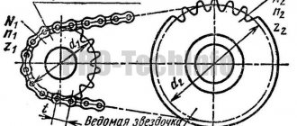
The chain consists of sprockets and a chain with rollers. The transmitted speed, force and direction of rotation do not change. Chain drives are widely used in transport mechanisms and on conveyors.
Gear Characteristics
In a gear drive, the driving and driven parts interact directly through the meshing of teeth. The basic rule for the operation of such a node is that the modules must be identical. Otherwise, the mechanism will jam. It follows that the diameters increase in direct proportion to the number of teeth. Some values can be replaced by others in calculations.
Modulus is the size between identical points of two adjacent teeth.
For example, between axes or points on an involute along the center line. The module size consists of the width of the tooth and the gap between them. It is better to measure the module at the point of intersection of the base line and the axis of the tooth. The smaller the radius, the more the gap between the teeth along the outer diameter is distorted; it increases towards the top from the nominal size. Ideal involute shapes can practically only be found on a rack. Theoretically, on a wheel with a maximally infinite radius.
The part with fewer teeth is called a gear. Usually it is leading, transmitting torque from the engine.
The gear wheel has a larger diameter and is driven in a pair. It is connected to the working unit. For example, it transmits rotation at the required speed to the wheels of a car or the spindle of a machine tool.
Typically, gearing reduces the number of revolutions and increases power. If in a pair there is a part with a larger diameter, the drive gear, at the output, the gear has a greater number of revolutions and rotates faster, but the power of the mechanism decreases. Such gears are called downshifts.
Why do we need a parasite?
When the gear and wheel interact, several quantities change at once:
- number of revolutions;
- power;
- direction of rotation.
Only in planetary units with teeth cut along the inner diameter of the ring, the direction of rotation is maintained. With external gearing, two identical gears are placed in a row. Their interaction does not change anything except the direction of movement. In this case, both gear parts are called gears, the wheel is not. The second, intermediate, is called “parasitic”, since it does not participate in the calculations and only changes its sign.
Types of gear connections
Gearing can have different tooth shapes on parts. This depends on the initial load and the location of the axes of the mating parts. There are types of gear movable joints:
- straight teeth;
- helical;
- chevron;
- conical;
- screw;
- worm
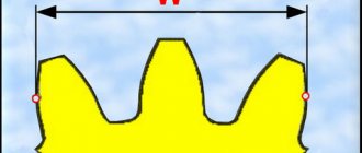
The most common and easiest to perform is spur gearing. The outer surface of the tooth is cylindrical. The arrangement of the gear and wheel axes is parallel. The tooth is located at right angles to the end of the part.
When it is not possible to increase the width of the wheel, but a large force must be transmitted, the tooth is cut at an angle and thereby increases the contact area. The calculation of the gear ratio does not change. The unit becomes more compact and powerful.
The disadvantage of helical gearing is the additional load on the bearings. The force from the pressure of the leading part acts perpendicular to the contact plane. In addition to the radial force, an axial force appears.
The chevron connection allows you to compensate for the stress along the axis and further increase the power. The wheel and gear have 2 rows of oblique teeth directed in different directions. The transmission number is calculated similarly to a spur gear according to the ratio of the number of teeth and diameters. Chevron gearing is difficult to implement. It is installed only on mechanisms with a very heavy load.
In a bevel gear transmission, the axes are located at an angle. The working element is cut along a conical plane. The gear ratio of such pairs can be equal to 1, when it is only necessary to change the plane of action of the force. To increase power, a semicircular tooth is cut. The transmitted number of revolutions is calculated only by tooth; the diameter is mainly used when calculating the dimensions of the unit.
The helical gear has a tooth cut at an angle of 45⁰. This allows the axes of the working elements to be positioned perpendicularly in different planes.
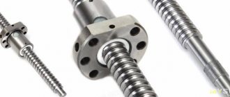
A worm gear does not have a gear; it is replaced by a worm. The axes of the parts do not intersect. They are located perpendicularly in space, but in different planes. The gear ratio of a pair is determined by the number of thread starts on the worm.
In addition to those listed, other types of gears are also produced, but they are extremely rare and are not standard.
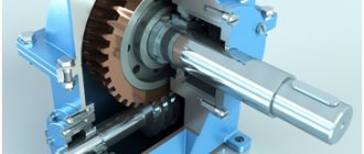
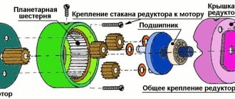
Multi-stage gearboxes
How to choose the right gear ratio. The engine usually produces several thousand revolutions per minute. At the output - the wheels of the car and the spindle of the machine, such a rotation speed will lead to an accident. The power of the actuating mechanism is not enough for the working tool to cut metal and the wheels to move the car. One pair of gears will not be able to provide the required reduction, or the driven part must be of enormous size.
A multi-stage knot with several pairs of gears is created. The gear ratio is calculated as the product of the numbers of each pair.
Uр = U1×U2 × … ×Un;
Where:
Uр – gear ratio;
U1,2,n – each of the pairs.
Before choosing the gear ratio, you need to decide on the number of pairs, the direction of rotation of the output shaft, and do the calculation in reverse order, based on the maximum permissible wheel dimensions.
In a multi-stage gearbox, all the gear parts located between the drive gear at the input to the gearbox and the driven ring gear on the output shaft are called intermediate. Each individual pair has its own gear, gear and wheel.
Gearbox and gearbox
Any gearbox with gears is a gearbox, but the reverse is not true.
The gearbox is a gearbox with a movable shaft on which gears of different sizes are located. Shifting along the axis, it includes first one or another pair of parts in the work. The change occurs due to the alternate connection of various gears and wheels. They differ in diameter and transmitted number of revolutions. This makes it possible to change not only the speed, but also the power.
Car transmission
In the machine, the translational movement of the piston is converted into rotational movement of the crankshaft. The transmission is a complex mechanism with a large number of different components interacting with each other. Its purpose is to transmit rotation from the engine to the wheels and regulate the number of revolutions - the speed and power of the car.
The transmission includes several gearboxes. This is, first of all:
- gearbox - speeds;
- differential.
The gearbox in the kinematic diagram is located immediately behind the crankshaft and changes the speed and direction of rotation.
By switching - moving the shaft, the gears on the shaft are connected alternately to different wheels. When the reverse gear is engaged, the direction of rotation changes through the parasite, and as a result the car moves backwards.
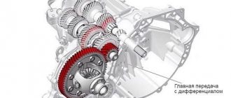
The differential is a bevel gear with two output shafts located in the same axis opposite each other. They look in different directions. The gear ratio of the gearbox - differential is small, within 2 units. It changes the position of the axis of rotation and direction. Due to the arrangement of bevel gears opposite each other, when engaged with one gear, they rotate in one direction relative to the position of the vehicle's axle, and transmit torque directly to the wheels. The differential changes the speed and direction of rotation of the driven tips, and behind them the wheels.
Gear Equation
It trades high input speed for greater output torque. This exchange occurs according to a very simple equation, which can be written as follows:
Input torque * Input speed = Output torque * Output speed
The input speed can be found by simply looking at the drive motor nameplate. The input torque can be easily determined by this speed and mechanical power from the same plate. Then we simply plug the output speed or required torque into the right side of the equation.
For example, let's say that your induction motor has a speed of 50 rps with an output torque of 0.5 N∙m, but you only want 5 rps. Then your equation will look like this:
0.5 N∙m * 50 r/s = Output torque* 5 r/s.
Your torque output will be 5 Nm.
Now let's say that with the same motor you need 5 Nm, but a minimum speed of 10 rps is required. How would you know if your motor and gear train (that is, essentially a geared motor) is capable of this? Let's look again at our equation
0.5 N∙m * 50 r/s = 5 N∙m * Output speed,
Output speed = 5 rps.
So, you have determined, using a simple equation, that with the indicator Output torque = 5 N∙m, your gear transmission is not capable of providing an output speed of 10 rps. You just saved yourself a ton of money because you didn't spend it on a machine that would never work.
How to calculate gear ratio
The gear and wheel have a different number of teeth with the same module and proportional diameters. The gear ratio shows how many revolutions the driving part will make to turn the driven part a full circle. Gears have a rigid connection. The transmitted number of revolutions in them does not change. This negatively affects the operation of the unit under conditions of overload and dust. The tooth cannot slip like a belt on a pulley and breaks.
Calculation without resistance
When calculating the gear ratio, the number of teeth on each part or their radii are used.
u12 = ± Z2/Z1 and u21 = ± Z1/Z2,
Where u12 is the gear and wheel gear ratio;
Z2 and Z1 are the number of teeth of the driven wheel and drive gear, respectively.
The “+” sign is placed if the direction of rotation does not change. This applies to planetary gearboxes and gears with teeth cut along the inner diameter of the wheel. If there are parasites - intermediate parts located between the drive gear and the ring gear, the direction of rotation changes, as with an external connection. In these cases, “–” is placed in the formula.
When two parts are externally connected by means of a parasite located between them, the gear ratio is calculated as the ratio of the number of teeth of the wheel and gear with the “+” sign. The parasite does not participate in the calculations, it only changes the direction, and accordingly the sign in front of the formula.
Typically, the clockwise direction of movement is considered positive. The sign plays a big role in the calculations of multi-stage gearboxes. The gear ratio of each gear is determined separately according to the order in which they are located in the kinematic chain. The sign immediately shows the direction of rotation of the output shaft and the working unit, without additional diagramming.
Calculation of the gear ratio of a gearbox with several gears - multi-stage, is defined as the product of gear ratios and is calculated by the formula:
u16 = u12×u23×u45×u56 = z2/z1×z3/z2×z5/z4×z6/z5 = z3/z1×z6/z4
The method of calculating the gear ratio allows you to design a gearbox with predetermined output values of the number of revolutions and theoretically find the gear ratio.
The gearing is rigid. The parts cannot slide relative to each other, as in a belt drive, and change the ratio of the number of rotations. Therefore, the output speed does not change and does not depend on overload. The calculation of the angular speed and the number of revolutions turns out to be correct.
Gear efficiency
To actually calculate the gear ratio, additional factors must be taken into account. The formula is valid for angular velocity; as for the moment of force and power, they are much less in a real gearbox. Their value is reduced by the resistance of transmission moments:
- friction of contacting surfaces;
- bending and twisting of parts under the influence of force and resistance to deformation;
- losses on keys and splines;
- friction in bearings.
Each type of connection, bearing and assembly has its own correction factors. They are included in the formula. Designers do not make calculations for the bending of each key and bearing. The directory contains all the necessary coefficients. If necessary, they can be calculated. The formulas are no different from simplicity. They use elements of higher mathematics. The calculations are based on the ability and properties of chromium-nickel steels, their ductility, tensile strength, bending, fracture and other parameters, including the dimensions of the part.
As for bearings, the technical reference book from which they are selected contains all the data for calculating their operating condition.
When calculating power, the main indicator of gearing is the contact patch, it is indicated as a percentage and its size is of great importance. Only drawn teeth can have an ideal shape and touch throughout the entire involute. In practice, they are manufactured with an error of several hundredths of a mm. When the unit operates under load, spots appear on the involute in places where the parts interact with each other. The more area on the tooth surface they occupy, the better the force is transmitted during rotation.
All coefficients are combined together and the result is the gearbox efficiency value. The efficiency is expressed as a percentage. It is determined by the ratio of power on the input and output shafts. The more gears, connections and bearings, the less efficiency.
Gear efficiency
Unfortunately, in a gear train you have certain energy losses. This is due to obvious reasons such as friction, pressure angle mismatch, lubrication, clearances (the distance between the meshed teeth of two gears), and angular momentum, etc. Different types of gears, different types of gears, different materials and wear of gears, - all this will affect the transmission efficiency. Their possible combinations will give too large a list, so you can find the exact value of the efficiency of the gear you are using in the documentation for it.
Let's assume you are using two spur gears. The typical efficiency of such a transmission is approximately
90%. Multiply this number by your output speed and output torque to get the true transmission output values.
If (from the previous example):
Gear ratio = 2/3
Output torque = Input torque * 2/3 = 1 N∙m,
Output speed = Input speed * 3/2 = 150 rps,
True output torque = 1 N∙m * 0.9= 0.9 N∙m,
True Output Speed = 150 rps * 0.9 = 135 rps.
Cylindrical helical gears (efficiency
They work in the same way as spur gears to transmit torque between parallel shafts, but this gear engages more smoothly. As a result, they create less noise during operation and have smaller dimensions. They have a large load capacity. Unfortunately, due to the complex tooth shape, they tend to be more expensive.
Worm gears (efficiency
This is a transmission with a worm screw on one shaft and a worm wheel on a second, perpendicular to the first, shaft. They have a very high gear ratio. The calculations take into account the fact that the worm (single-threaded) has only one tooth (turn).
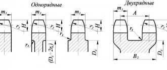
To perform calculations, drawings and sketches of gears and other gear parts, you need to know the basic elements and parameters of gears and conventions adopted for depicting a ring gear.
Rice. 17. Gears with elements of fixation on the shaft
The main element of a gear is the tooth.
The initial surface divides the tooth according to its height into two unequal parts - the head and the stem.
The part of the tooth located above the dividing surface is called the tooth head, and the part located below the dividing surface is called the tooth stem. The teeth with the rim make up the crown of the gear, which is connected through a disk or spokes to a hub that has a hole for the shaft, often with elements for fixing the wheel on the shaft, for example, using a key (Fig. 17, a
) or spline (Fig. 17,
b) )
connections.
Read also: How to make a chuck for a mini drill
Types of gears
Any gear, regardless of its type, is made and operates according to the same principles above. However, their different types allow you to perform different tasks. Some types of gears have either high efficiency, or a high gear ratio, or work with non-parallel axes of gear rotation, for example. Below are the main common types. This is not a complete list. A combination of the following types is also possible.
Note: Only typical gear efficiencies are shown. Due to many other possible factors, the efficiencies given should be used as reference values only. Manufacturers often list expected efficiencies in data sheets for their gears. Remember that wear and lubrication will also significantly affect the efficiency of the gears.
Gear design and parameters
It contains a ring with teeth, a disk and a hub. There are three most important parameters: module, pitch circle diameter and number of teeth. What pitch circle does a gear wheel have? A drawing of a spur wheel with typical involute teeth is shown below.
Read also: How much gold is in microcircuits
For example, a gear with 22 teeth and a diameter of 44 mm has a module m = 2 mm. The meshed gears must both have the same module. Their values are standardized, and it is on the pitch circle that the module of a given wheel takes on its standard value.
The height of the tooth head of one wheel is less than the height of the tooth foot of the second one, which engages with it, due to which a radial clearance c is formed.
To ensure the lateral clearance δ between two meshed teeth, the sum of their thicknesses is taken to be less than their circumferential pitch p. Radial and lateral clearances are provided to create the necessary conditions for lubrication, normal operation of the gear in case of inevitable inaccuracies in manufacturing and assembly, thermal increase in the size of the gear, etc.
Cylindrical spur gears (efficiency
A spur gear has teeth arranged on a cylindrical surface. Gears with them are the most commonly used types due to their simplicity and maximum efficiency among all others. Gear ratio for one pair u ≤ 12.5. Not recommended for very high loads as straight gear teeth break quite easily.