Grinding speed. Grinding depth (cross feed). Longitudinal feed.
Grinding speed.
The rotation speed of the workpiece is very small compared to the speed of the grinding wheel, so it is neglected and the grinding speed is called the grinding wheel speed.
The rotation speed of the wheel is of great importance for the grinding process. The productivity of the grinding process increases with increasing wheel speed.
Speeds must be selected according to the highest permissible values specified in GOST 4785-64 (depending on the shape of the wheel, bond, material being processed, type of grinding, machine design).
Example. Determine the speed of the grinding wheel vк, if Dк = 600 mm and nк = 1100 rpm are known.
Therefore, they try to use a circle of the largest diameter that can be installed on the machine, and choose the largest possible number of spindle revolutions. The limitation on the speed of a circle is, as has already been said, its strength and the rigidity of the machine, fixture, and part. With low system rigidity, high speeds lead to vibrations that reduce accuracy, the roughness class of the machined surface, and increase wheel wear.
There is such a relationship between the speed of the part vd, the material being processed, the life of the wheel, the transverse and longitudinal feeds
where vд is the speed of the part during external cylindrical grinding, m/min; Cv is a coefficient depending on the material of the part, heat treatment, and grinding wheel; d—diameter of the treated surface, mm; T — wheel life, min; st—cross feed, mm/stroke; spr — longitudinal feed in fractions of the wheel width; ρ, m, x, y are exponents.
The values of Cv, ρ, m, x, y are given in reference books.
Having received the calculated value vd, find the corresponding number of revolutions, parts nd
Using the machine's passport, the nearest lower number of revolutions nst is found and processing is carried out at these revolutions. In this case, the actual rotation speed of the part will be slightly less than the calculated one. It is determined by the formula
Grinding depth (cross feed). When rough grinding, it is advantageous to work with the greatest depth of cut (grinding) allowed by the grain of the wheel, the part and the machine. In this case, the cutting depth should not exceed five hundredths of the transverse grain size. So, for a 50-grit wheel it should be less than 0.025 mm. When the cutting depth increases beyond the permissible limit, the pores of the wheel are quickly filled with metal shavings and the wheel becomes greasy.
The grinding depth should be reduced when processing a non-rigid part that is poorly secured to the machine, and when burn marks occur. When finishing grinding, the grinding depth should be small, which increases the accuracy and roughness class of the processing.
Hard and durable materials are ground to a shallower depth. As the grinding depth increases, the power spent on friction and chip crushing increases.
Longitudinal feed. Longitudinal feed is measured in fractions of the wheel width. For rough grinding, it is 0.4-0.85 wheel widths per revolution of the part. A larger feed value than 0.9 cannot be accepted, because with a larger feed, a helical, unpolished strip will remain on the surface of the sanded part.
During finishing work, the longitudinal feed ranges from 0.2 to 0.4 of the wheel width per revolution of the part. The higher the feed, the higher the productivity, but the higher the surface roughness. The most rational cutting modes (vк, vд, spр) are selected according to the standards given in reference books.
When determining cutting modes according to standards, first determine the speed of the part vd (at the accepted speed of the circle, dimensions of the part), then the longitudinal feed spr and transverse feed st (Tables 7 and 8).
7. External cylindrical grinding modes
Parameters taken into account when performing calculations
When calculating the cutting conditions of tools, the following indicators are used.
- Cutting depth. The distance to which the tool is immersed during processing of the workpiece.
- Innings. The degree of movement of the tool within one working stroke.
- Cutting speed. The ratio of the speed of movement of the cutting edge to the time spent processing the part.
- Design dimensions. Workpiece parameters. These include the diameter, length and width of the surface being processed.
When selecting metal cutting conditions, processing allowances, time spent and number of passes are taken into account.
Example of calculation of cutting conditions (cylindrical external grinding)
Grind the shaft journal made of steel 40X (hardened) HRC
>50 with diameter d=45k6, machined surface roughness
Ra
=0.63 microns, side allowance
t
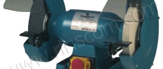
=0.2 mm. The equipment is a cylindrical grinding machine model 3A151 (Fig. 2.7).
Machine specifications: Maximum diameter and length of the grinding surface: 200x700 mm. Wheel head motor power N
m=7 kW; Machine efficiency η=0.8.
Rotation speed of the workpiece (min -1): 63…400 (steplessly adjustable). The rotation speed of the grinding wheel is 1112 min -1. The longitudinal speed of the table is 0.1…6 m/min (steplessly adjustable).
Periodic feed of the grinding wheel (mm/table stroke): 0.0025; 0.005; 0.0075; 0.01; 0.0125; 0.015; 0.0175; 0.02; 0.0225; 0.025; 0.0275; 0.03; 0.0325; 0.035; 0.0375; 0.04; 0.0425; 0.045; 0.05. Grinding wheel dimensions (new): D
k=600mm;
B
k=63mm.
1. Select the characteristics of the grinding wheel (Table 2.31) 24A16…25S1K. The shape of the PP circle is a rectangular profile; abrasive grain material – white electrocorundum; grain size 16...25; ligament hardness – medium; the bond is ceramic.
2. Grinding speed for a wheel of this type V
kr=35 m/s On the machine, the circle rotates with a rotation speed
n
= 1112 min -1.
4. Accepted grinding wheel life in minutes (usually 15 minutes).
Processing with cutters
When assigning cutting modes, the order of material processing is determined, and the specific impact of the tool on the workpiece is taken into account.
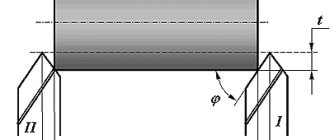
Rice. 1 Metal processing with a cutter (schematic diagram)
Figure 1 shows the indicators that affect the turning cutting mode:
- t – cutting depth;
- s – feed;
- f – area of the nominally cut layer;
- H – height of the residual section;
- ϕ – main angle;
- ϕ1− auxiliary angle.
The selection of feeding modes is carried out according to special tables.
Table 1. Calculation of feed for non-hardened steels and cast irons
Table 2. Feed calculation for hardened steels
The following link will help you get acquainted with the range of turning tools used in calculating the cutting conditions of metals.
Rice. 2 Work of a metal cutter
Milling
When calculating general machine cutting conditions using cutters, the geometric parameters of the cutting part of the tool are taken into account:
- back and front corner;
- angle of inclination of the helical groove of the teeth;
- main and auxiliary angle in terms of the corner edge;
- additional angle in the lead, in case of double sharpening of edges;
- cutting edge angle.
Additional information about the characteristics of milling tools can be obtained through reference books and production documents. The latter are provided by the manufacturer at the buyer's request.
The following table will help you calculate the cutter feed when working with steels, steel castings and cast irons.
Table 7. Calculation of cutter feed when working with various materials
The durability indicators of cutters are also presented as reference values.
Table 8. Durability of cutters in minutes
In the case of high-speed milling on mechanized equipment, additional values and coefficients are applied.
Table 9. Average cutting speeds when working with cast iron, carbon and alloy steels
When determining the parameters of the cutting mode, the design power, force and cutting torque, as well as the main technological time are taken into account.
The article “Milling with end mills” will help you obtain additional information regarding working with milling tools. To get acquainted with the list of cutters for metal, go to the appropriate section of the catalog.
Rice. 6 Work of a cutter for metal
Drilling
Operating modes with drills are determined taking into account the configuration of the tool, the parameters of the workpieces and the specifics of the equipment used. Typically, formulas and table values are used. They allow you to select the cutting mode for drills with high accuracy.
To calculate the drill feed, the formula s = C x D0.6 is used, in which:
- s – feed;
- D – diameter of the drill used;
- C – standard coefficient.
The coefficient values are presented in the table.
Table 3. Values of coefficient C for drills
Force, feed and cutting torque are calculated using standard formulas using the appropriate coefficients.
Table 4. Coefficients allowing to calculate cutting conditions for drills
Correct use of cutting calculation tables and formulas will allow you to select the optimal mode. It will ensure high tool efficiency and minimal costs for subsequent processing of the part.
To familiarize yourself with drills involved in various steel cutting modes, visit the metal drills section.
Rice. 3 Work of a drill for metal
Working with sweeps
Reamers are used for preliminary and final processing of workpieces. They allow you to create holes of the required quality and shape. The tool is in demand in production and at home.
The calculation of cutting mode parameters is carried out taking into account the following reaming indicators:
- groove angle;
- rear corner;
- front corner;
- cone angle of the fence part.
When working with carbide inserts, the feed is determined according to the table.
Table 5. Feed of reamers with carbide inserts
Standard values also help determine the durability of products.
Table 6. Durability of sweeps in minutes
A complete list of sweeps used in organizing technological operations is presented in the corresponding section. Specialists have access to tools for manual and mechanized work. The range includes solutions working with cast iron, non-ferrous metals, structural and alloy steels.
Rice. 5 Sweep operation