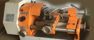
Table-top machines TV-9 and TV-7M are multifunctional, small-sized equipment that is designed for turning operations using workpieces weighing no more than 5 kg. Ease of use, accessibility and reliability have made the products in demand in educational institutions and repair and installation organizations that use compact tools for fast and accurate grooving, boring, drilling, threading, trimming, and cutting parts. The machines have a traditional arrangement of the main elements and a well-developed kinematic diagram, thanks to which it is possible to process parts with accuracy class “H”.
Main technical characteristics of the TV-9 machine
* The TV-11 screw-cutting lathe is no longer produced by the plant
| Parameter name | TV-7M | TV-9 | TV-11* |
| Basic machine parameters | |||
| Accuracy class | N | N | N |
| The largest diameter of the workpiece above the bed, mm | 220 | 220 | 240 |
| The largest diameter of the workpiece above the support, mm | 100 | 100 | 110 |
| Height of centers above flat bed guides, mm | 120 | 120 | 130 |
| Maximum length of the workpiece at centers (RMC), mm | 275 | 525 | 750 |
| Maximum length of the workpiece in the chuck, mm | 250 | 500 | |
| Maximum height of the cutter holder, mm | 16 x 16 | 16 x 16 | 16 x 16 |
| Maximum mass of workpiece processed, kg | 5 | 10 | |
| Spindle | |||
| Threaded end of spindle, mm | M45 x 4.5 | M45 x 4.5 | M45 x 4.5 |
| Diameter of standard cartridge, mm | 125 | 125 | 125 |
| Diameter of through hole in spindle, mm | 18 | 18 | 18 |
| Morse taper spindle | №3 | №3 | №3 |
| Number of speed steps for direct spindle rotation | 6 | 6 | b/s |
| Spindle direct rotation frequency, rpm | 60, 105, 185, 315, 555, 975 | 60, 105, 185, 315, 555, 975 | 40..2000 |
| Number of spindle reverse rotation frequency steps | 6 | 6 | b/s |
| Spindle reverse rotation frequency, rpm | 60, 105, 185, 315, 555, 975 | 60, 105, 185, 315, 555, 975 | 40..2000 |
| Spindle braking | No | No | |
| Handle lock | No | No | |
| Caliper. Submissions | |||
| Maximum longitudinal movement of the caliper, mm | |||
| Longitudinal movement of the caliper by one dial division, mm | 0,25 | 0,25 | 0,25 |
| Maximum lateral movement of the caliper, mm | |||
| Transverse movement of the caliper by one division of the dial, mm | 0,025 | 0,025 | 0,025 |
| Maximum movement of the upper (incisor) slide, mm | 85 | 85 | 85 |
| Movement of the cutting slide by one division of the dial, mm | 0,025 | 0,025 | 0,025 |
| Angle of rotation of the cutting slide, degrees | ±40° | ±40° | ±40° |
| Number of stages of longitudinal feed of the caliper | 6 | 6 | |
| Limits of longitudinal working feeds of the caliper, mm/rev | 0,1; 0,12; 0,16; 0,20; 0,24; 0,32 | 0,1; 0,12; 0,16; 0,20; 0,24; 0,32 | 0,04..0,31 |
| Limits of working cross feeds of the caliper, mm/rev | No | No | No |
| Number of metric threads to be cut | 6 | 6 | |
| Limits of pitches of cut metric threads, mm | 0,1; 0,12; 0,16; 0,20; 0,24; 0,32 | 0,1; 0,12; 0,16; 0,20; 0,24; 0,32 | 0,8..2,5 |
| Tailstock | |||
| Morse taper tailstock | №2 | №2 | №2 |
| Maximum movement of the quill, mm | 65 | 65 | 65 |
| Electrical equipment | |||
| Main drive electric motor, kW | 0,75 | 1,1 / 380 | 1,1 / 380 |
| Dimensions and weight of the machine | |||
| Machine dimensions (length width height), mm | 1120 x 640 x 680 | 1405 x 620 x 730 | 1600 x 650 x 690 |
| Machine weight, kg | 220 | 230 | 245 |
Bibliography:
Screw-cutting lathe TV-9. Passport, 2013
Acherkan N.S. Metal-cutting machines, Volume 1, 1965
Batov V.P. Lathes, 1978
Beletsky D.G. Handbook of a universal turner, 1987
Denezhny P.M., Stiskin G.M., Thor I.E. Turning, 1972. (1k62)
Denezhny P.M., Stiskin G.M., Thor I.E. Turning, 1979. (16k20)
Lokteva S.E. Computer controlled machines, 1986
Modzelevsky A. A., et al. Lathes, 1973
Pikus M.Yu. A mechanic's guide to machine repair, 1987
Skhirtladze A.G., Novikov V.Yu. Technological equipment for machine-building industries, 1980
Tepinkichiev V.K. Metal cutting machines, 1973
Chernov N.N. Metal cutting machines, 1988
Related Links. Additional Information
- Classification and main characteristics of turning machines
- Selecting the right metalworking machine
- Multi-start thread. Methods for cutting multi-start threads on a lathe
- Graphic signs for lathes
- Friction clutch of a screw-cutting lathe
- Lathe repair technology. Repair of bed and support guides
- Lathe repair technology. Repair of headstock and tailstock
- Lathe spindle repair
- Methodology for checking and testing screw-cutting lathes for accuracy
- Directory of lathes
- Manufacturers of lathes
Home About the company News Articles Price list Contacts Reference information Interesting video KPO woodworking machines Manufacturers
Specifications
Tabletop lathes 16T02P have several design features that determine the nuances of technical characteristics.
Common parameters
Main technical characteristics of the equipment in question with accuracy class P:
- the size of the workpiece being processed above the bed is 12.5 cm;
- above the caliper – 5 cm;
- workpiece length at centers – 250 mm;
- the height of the centers above the flat controls of the bed is 68 mm.
There are also certain differences for individual design elements, which determine higher accuracy and other advantages of the equipment.
Spindle
The spindle is located in the headstock housing and is mounted on three ball bearings. The front support has angular contact bearings. Spindle Specifications:
- direct rotation frequency stages – 6;
- direct rotation frequency – 400-4000 rpm;
- through hole diameter – 10.2 mm.
On the headstock body there are two special eyes for monitoring the oil level and filling the bearing grooves with oil.
Caliper and feed
The longitudinal movement of the caliper is carried out manually. The caliper has the following technical specifications:
- maximum lateral movement of the caliper – 60 mm;
- per one division, the transverse movement of the caliper is 0.01 mm;
- the upper incisor slide moves 65 mm;
- The upper carriage rotates in the range of +- 30°.
A cross-mounted support in a machine with the possibility of longitudinal and transverse movement of the slide. Both types of movement are performed manually.
Attaches to the frame using an eccentric clamp. The maximum movement of the quill at the tailstock is 4 cm.
Electrical equipment
The machine is equipped with a main drive electric motor with a power of 0.25 kW. Main characteristics of electrical equipment:
- network power – 380 V;
- power consumption – 11 kW;
- control network power – 110 V;
- frequency – 50 Hz.
The electric motor is started by pressing a button. To limit idle speed, there is a time relay; to protect the electric motor from overload, there is a thermal relay in the circuit.
Dimensions and weight
The tabletop machine is light in weight compared to its analogues. This creates convenience for small workshops and private workshops, including watchmakers. The total weight of the equipment according to the passport is 35 kg. The dimensions of the unit are as follows:
- length – 5 cm;
- width – 52 cm;
- height – 30 cm.
This allows you to place the machine in limited space.
Types of work carried out
The TV-9 screw-cutting lathe is designed for the following work:
- Creating a cylindrical and conical surface. The installed dial allows you to move the support with the cutting tool simultaneously in the longitudinal and transverse directions, due to which a conical surface is obtained.
- Also, when using special equipment, you can drill holes.
- Cutting of workpieces is carried out by installing a cutting cutter and transverse feed.
- The operating instructions provide for the possibility of performing work on cutting various threads on a cylindrical surface. To do this, you can adjust the guitar with replacement wheels, which is hidden in the headstock housing.
- End trimming.
Front headstock of the TV-9 machine
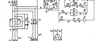
The electrical circuit of the TV-9 machine determines the presence of a fast feed function to speed up the processing process. The purpose of the TV-9 turning group determines its wide versatility in application. At the same time, it allows you to obtain parts with high-precision dimensions and roughness indicators. The tests carried out indicate that when installing a cutter with a diamond plate as a cutting edge when processing steel 45, the roughness index is no more than Ra 0.2 µm. When turning, a manual feed system can be used, the controls of which have a measuring scale.
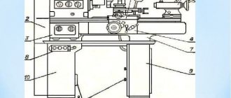
Structural elements of equipment
The TV-6 model lathe consists of the following components:
- feed control box;
- front and rear cabinets;
- protective screen;
- trough for supplying lubricating oil;
- headstock;
- device apron;
- tailstock;
- supporting frame;
- electrical system elements;
- guitar;
- protective casing.
Main components and controls of the TV-6 machine
The feedbox of the TV-6 lathe, driven by a gearbox using transmission gears, consists of:
- two shafts;
- five gears with different parameters;
- block gears;
- running roller;
- couplings;
- round nut;
- shift handles;
- drain plug.
The handle on the front side of the feed box allows you to determine the parameters of the thread cut on the workpiece.
Another handle, located on the feed box panel, is responsible for turning on the machine’s running roller. The design of this unit of the TV-6 machine makes it impossible to simultaneously turn on the lead screw and the lead roller. Models of lathes belonging to the category of industrial equipment are also equipped with a similar safety system. Lubrication of all feed box components (gears and rubbing surfaces) is ensured by oil supplied from the trough using special wicks.
Headstock device
Tailstock device
The front cabinet has a U-shaped configuration, and to enhance its rigidity, there are special ribs in its upper and lower parts. On its back side there is a drive electric motor of the unit, and on the front side there is a button that controls its reversing switches. The rear TV-6 cabinet has a similar design; a panel with electrical equipment is mounted on it.
The tailstock, which has a mounting hole for Morse taper No. 2, includes the following elements:
- base;
- unit body;
- connecting screws;
- quill;
- key screw;
- flywheel to control the movement of the quill;
- handles for fixing the quill and the tailstock itself.
The tailstock design allows the quill to be moved up to 65 mm.
The frame of the device, due to which all its structural units are connected and supported in a given position, has a box-like structure with several windows. There are two prismatic guides on the frame, along one of which (front) the carriage moves, and along the second (rear) the tailstock of the unit moves. The load-bearing elements of the frame itself, in the front part of which a rail with a lead screw is attached, are two pedestals.
The most important mechanism of the TV-6 lathe is its apron, in which it is necessary to highlight the following elements:
- four gears (two worm and two rack and pinion);
- control handles;
- handwheel for manual feed control;
- queen nut;
- a running roller responsible for the longitudinal feed of the caliper;
- shaft.
The support of the TV-6 screw-cutting lathe is composed of four carriages. This piece of equipment is responsible for fixing the cutting tool and moving it during metal processing. The tool holder, in which the working tool is fixed, is located on carriage No. 4; it is capable of moving along the guides of carriage No. 3 only in the longitudinal direction. The rotating carriage is No. 3, which is mounted on the second carriage. Carriage No. 2 is mounted on carriage No. 1, it is capable of moving along its guides in the transverse direction. Carriage No. 1 moves along the frame guides - in the longitudinal direction.
In order to transmit rotation from the gearbox of the unit to the elements of the feedbox, a transmission mechanism, also called a guitar, is used. The main structural element of the guitar is the bracket on which the gears are mounted. There are no replacement gears for the TV-6 machine, so the gear ratio provided by the guitar is constant and amounts to ¼.
TV-6 machine gearbox
Features of the TV-9 model
TV-9 has successfully passed laboratory tests of the Russian Ministry of Defense, which determines high-quality assembly and proper reliability. TV-9 can be characterized as follows:
- Rational layout.
- Optimal, well-thought-out arrangement of main components and controls.
- Low maintenance frequency.
- Reliability of all installed components.
- Applicability in the manufacture of high-precision parts.
Mechanics of the TV-9 machine
You can also note the fact that angular contact bearings are installed in the spindle supports. The high rigidity of the entire structure with the above-mentioned bearings ensures damping of vibration loads, resulting in a reduction in the degree of scrap during turning. When creating the TV-9 design, the possibility of its additional equipment was taken into account to significantly expand the scope of application. The manufacturer's description indicates that the model can be confidently used for processing parts weighing up to 10 kilograms. Moreover, when installing a wear-resistant cutter and selecting optimal processing modes based on the workpiece material, it is possible to remove 4 mm per diameter in one pass.
Design and operation of the Universal-3 lathe
A hollow cylindrical guide is fixed to the machine bed. It is the common base for the main components of the machine: spindle head, caliper, tailstock. Another common base for these units is the flat bed guide.
In the front part of the frame, under the casing, there is a lead screw for longitudinal movement of the caliper.
A bracket is installed on the left wall of the headstock. The electric motor driving the machine is mounted on it.
Under the casing covering the bracket, there are spindle rotation drive pulleys and a feed drive mechanism.
The machine is supplied in a lathe version. The additional accessories included in the delivery set (see Table 7) are used to implement other versions of the machine with the help of simple changeovers: milling and drilling, grinding, jointing, etc.
The design of additional accessories is described below and methods for setting them up for various types of processing are given.
Tool holders
The delivery set includes two tool holders: movable and fixed.
Using a movable tool holder mounted on a carriage, conical surfaces can be processed. The fixed tool holder is attached to the slide of the caliper using a screw and a block that fits into one of the T-shaped grooves of the slide. There are two screws in the carriage, which, using the same crackers, secure the carriage to the caliper slider.
In general, the carriage can be installed in any of the grooves of the caliper slide in accordance with the adjustment requirements.
To process conical surfaces, the carriage should be installed on the slider so that the initial zero stroke of the carriage scale coincides with the mark on the left end of the slider. This installation is carried out using one screw in the base of the carriage, which is screwed into a threaded hole specially provided for this purpose, located on the upper plane of the slide between two T-shaped slots. The carriage scale division value is 1°.
ATTENTION! After turning the carriage to the required angle, it is necessary, in order to avoid an accident, to securely fix it with a fastening screw, as described above
Collet clamp
The clamp consists of a collet, a nut and a ring; the collet is inserted into the conical hole of the spindle, and the nut is screwed onto the spindle along the thread. With the help of this nut in the collet, moving along its axis, the workpiece or cutting tool inserted into its internal cylindrical hole is clamped.
The design of the unit, its main components
Description of the main components of the device:
- Peculiar cabinets. To increase the reliability of the unit’s design, the designers decided to make the lathe’s stand from a thick sheet of iron with transverse and longitudinal stiffeners. The front and back cabinets play the role of a support on which the device frame is installed. In such a structure, the unit control system and the main mechanisms of the device can be compactly placed. All the necessary equipment is installed in the rear part of the cabinet, including an asynchronous electric motor needed for the spindle head. The front panel houses the unit control system.
- Bearing frame. The main part of the structural elements of the device is fixed to this supporting base. The supporting structure has a box-like configuration and is equipped with two guides. The carriage moves on the front section, and the rear unit of the unit (headstock) moves on the back section.
- Tailstock. It is mounted on the left section of the main support. Various tools are attached to it.
- The screw cutting machine has an asynchronous motor and a feed unit. These nodes communicate the rotational movements of the spindle to the working shaft of the unit. The TV-4 equipment is equipped with a V-belt transmission unit. To control the degree of feed, use a special handle. The device excludes simultaneous rotational movements of the shaft and the working screw. The trough, located on top, is intended for the lubricant mixture to enter the working system of the machine.
- Headstock. This machine unit is considered the main mechanism of the unit. It contains an axis and a fastening system (three-jaw chuck), which places the workpiece in the desired position, which transmits the rotational movements of the drive to the product.
- Supporting unit of a metal-cutting device (caliper), holder, cutter. By means of these mechanisms, the parts installed in the headstocks of the machine are processed. The support is considered a unit for moving the cutter to the required position.
TV-4 lathe
Exploitation
The operating instructions draw attention, first of all, to the need to comply with safety measures. Basic Rules:
- Install the equipment on a rigid foundation; check the level of the installation with a level. The accuracy of the work largely depends on correct installation;
- reliably ground the machine in accordance with the requirements;
- use a wooden lattice as a stand;
- fasten the workpieces securely;
- use cutters with proper sharpening;
- secure the part in the chuck so that the cams grip it to the maximum possible extent;
Cartridge, the guides are clearly visible in the photo
- do not screw the cartridge by sudden braking;
- fasten in the chuck without emphasis on the center of the rear centered parts no more than two diameters long. For longer lengths, use the center;
- Having installed the parts in the centers, check the fixation of the tailstock;
- remove shavings in a timely manner using a crochet hook.
Machine care
For reliable and durable operation, the following rules must be followed:
- Before making switches, the machine must be completely stopped. If the gear pair does not engage or the gear clutch does not engage, turn the chuck by hand until the gears or clutch engage. Switching when the machine is not completely stopped leads to impacts, which causes rapid wear and breakage of gears and couplings.
- When installing the cartridge, clean the threads. Contaminated threads lead to chuck jamming and spindle breakage.
- Caliper seals require maintenance. Chips gradually accumulate in them, which damages the guides.
- Make sure that after the caliper there is no dirty mark on the guides. If a dirty mark becomes noticeable, it is washed off and the guides are lubricated with clean oil.
- The machine should not be overloaded. Overload causes increased noise, belts slip, bearings and the electric motor overheat.
- If the part is machined in the centers, the quill is extended to the smallest amount: the fastening will be secured more firmly, and the quill will last longer.
Lubrication
Timely lubrication guarantees trouble-free, long-lasting operation. Rubbing parts, screws, shafts, gears, bearings are subject to lubrication. The following components are lubricated:
- Headstock through the top cover. An oil level indicator is used to control the level.
- Reducing box through a plug. An oil level indicator is used to control the level.
- Feed box through the tray at the top. From there it is fed through wicks to the rubbing surfaces and gears. There should always be some oil in the trough. The accumulated oil is drained through the plug from below.
- Guitar: Grease is used to lubricate the gears and bushing.
- On the bed, all mechanisms, bearings, and guides are lubricated manually before starting work.
- Everything in the apron is lubricated through the hole at the bottom of the caliper. Lubrication is carried out every time before starting work.
- Everything in the caliper is lubricated by hand before work.
- Tailstock. Lubricate the quill and the screw support before work.
Screw-cutting lathe TV-7M
The model enjoys well-deserved popularity on the Russian market and in the CIS countries. Workshop owners consider the machine reliable, economical, undemanding to maintain and easy to repair. For the first time, consumers could take advantage of all the advantages of the equipment 35 years ago, when the Rostov plant launched the production of this model of small-sized, universal equipment. Production continues to this day, which is proof of the high popularity of the device.
Equipment Features:
- Unlike the TV-9 machine, it allows the use of workpieces no longer than 275 mm in the chuck.
- Suitable for creating holes, cutting off, grooving, boring, threading, trimming the ends of parts made of metal, wood, plastic.
- Has a six-speed gearbox.
- The spindle is mounted on three bearings. Two of them are located in the front and one in the rear support.
- The user can use 8 feeds and 6 thread sizes without first preparing the guitar for the task at hand.
The machine provides processing of materials with a high class of accuracy, which is maintained throughout the warranty period. The TV-7M machine is ideal for performing turning work in small production areas, as well as using it as an effective tool for teaching turning. The products are equipped with various accessories, operating instructions and devices that allow you to expand the functionality of the equipment.
Brief information about the manufacturer
The manufacturer of 16T02P machines is a plant in Vanadzor, Republic of Armenia. In the past it was the Kirovakan Precision Machine Tools Plant. The manufacturer produced 2 modifications of these machines: high precision and especially high precision. At the moment, the machines in question are no longer produced, but due to their durability and reliability they are still widely used.
Purpose
The main purpose of these machines is to use them in precision industries, as well as as educational material in schools and technical schools. Successfully performs fine and precise work on centers, collets, chucks and faceplates. The faceplate is used when working with large workpieces, and a collet chuck is used to secure thin parts.
The equipment is designed to perform all standard turning operations, including threading, boring holes, as well as milling and grinding operations on metal workpieces.
Industry
Thanks to its increased accuracy parameters, a table-top lathe is used in various industries that require fine processing of the workpiece.
Sentinel
This is the most commonly found machine in watch workshops; one might say it is a watch lathe. It is capable of accurately processing the smallest parts, with high precision requirements. Of all the possible analogues, this machine is the best option for small watch shops.
Radio engineering
This is another area of production that requires special precision in the processing of workpieces. In the radio engineering industry, 16T02P machines are used both in private workshops and in large-scale production.
Laboratories
The laboratories are also equipped with desktop machines for processing experimental workpieces. In terms of processing accuracy, the machines in question are the most optimal option.
Workshops
Small workshops do not require large, heavy machines. For production and work at such enterprises, standard desktop equipment is sufficient.
When teaching how to operate a lathe in schools, colleges and technical schools, desktop equipment is also used. Its performance and accuracy are enough to process training workpieces and learn how to carry out all the basic standard turning operations.
Classification of universal lathes
Types of screw-cutting lathes are distinguished depending on several parameters, which include:
- weight of equipment;
- the maximum length of the part allowed for processing on a screw-cutting lathe;
- the maximum diameter of such a part.
The length of a part processed on a screw-cutting lathe of one model or another depends on the distance maintained between its centers. If we consider the diameter of the workpiece, which can be processed by a specific universal screw-cutting lathe, then this parameter is in the range from 100 to 4000 mm. It should be borne in mind that machine models that can process parts of the same diameters may differ in the length of the workpieces processed.
Heavy screw-cutting lathe 1A670
Universal lathes can have different weights. So, according to this parameter, equipment is classified into one of the following categories:
- heavy machines, the weight of which can reach up to 400 tons (screw-cutting lathes of this category can process parts with a diameter of 1600–4000 mm);
- machines weighing up to 15 tons (such equipment can process parts with a diameter of 600–1250 mm);
- equipment weighing up to 4 tons (with a permissible diameter of processed parts of 250–500 mm);
- lightweight machines whose weight does not exceed 0.5 tons (such equipment can process parts with a diameter of 100–200 mm).
A lightweight universal lathe is a benchtop model that is typically used in home workshops or small businesses.
Screw cutting lathe CU500
The most common types of enterprises with such screw-cutting lathes are:
- experimental sites of enterprises in various industries;
- enterprises engaged in the production of watch movements;
- factories producing instruments and control equipment.
Enterprises in the energy and mechanical engineering industries are equipped with heavy-duty screw-cutting lathes. Devices of this type are also used for processing elements of special mechanisms and assemblies - parts:
- turbine mechanisms;
- for equipping railway transport (wheel sets, etc.);
- for completing heavy rolling equipment.
However, screw-cutting lathes belonging to the middle category are most widespread. It is through the use of such machines that it is possible to perform semi-finishing and finishing metalworking operations, as well as cut threads of various categories.
A universal lathe, which belongs to the middle category, has a number of significant advantages: a wide range of working tool feeds and spindle speeds, high structural rigidity and engine power, which allows you to perform a wide range of work with workpieces made of metal and other materials.
Medium-category screw-cutting lathes, in addition, are equipped with various mechanisms and devices that significantly expand their functionality, allow processing with greater precision, and make the work of operating personnel more comfortable and safe. Such elements of additional equipment, which is convenient, allow you to automate many processes of processing workpieces on screw-cutting lathes.
Separately, it should be said about screw-cutting lathes with numerical control (CNC), which in Soviet times were produced simultaneously by several enterprises. As a rule, enterprises that produced a large range of small-scale products were equipped with such machines. The design of a screw-cutting lathe of this type and the possibility of its quick changeover make it simply irreplaceable in situations where it is necessary to quickly switch to the production of parts of a different modification.
Screw-cutting lathe 1M63
Apron
An apron is necessary for feeding the caliper from the running roller (screw) mechanically or manually. If you need to feed manually, you should rotate the flywheel, which is located on the pinion shaft. The latter connects with the gear, which is located on the shaft of the rack and pinion gear.
A worm connected by a sliding key to a roller provides mechanical feed. It transmits the movement to the worm gear. From there, the movement is transmitted to the rack and pinion gear through the next gear and cam clutch. The jaw clutch is connected to a handle, the rotation of which leads to mechanical feed.