Information about the manufacturer of the screw-cutting lathe 16B05A
The manufacturer of the 16B05A screw-cutting lathe was the Odessa Machine Tool Plant .
Machine tools produced by the Odessa Machine Tool Plant (OSZ) and the Experimental Mechanical Plant (OMZ)
- 1P611
- high-precision screw-cutting lathe, Ø 250 - 16B05A
- especially high precision screw-cutting lathe, Ø 250 - 16B05P
- high-precision screw-cutting lathe, Ø 250, Kirovakan - 16M05A
- screw-cutting lathe of especially high precision, Ø 250 - 1601
— table lathe Ø 125 - 1604
— high-precision screw-cutting lathe, Ø 200 - 1613D
- precision screw-cutting lathe, Ø 240 x 270 - OT-4
- lightweight high-precision screw-cutting lathe, Ø 250 - OT-5
- high-precision, lightweight lathe-screw-cutting machine, Ø 250
16B05A screw-cutting lathe of particularly high precision. Purpose, scope
A particularly high-precision screw-cutting lathe 16B05A with a maximum processing diameter of 250 mm over the bed is designed to perform various high-precision turning operations performed in centers, collets, chucks and faceplates, as well as for cutting metric, inch and modular threads.
16B05A lathe provides high quality surface quality and work accuracy (accuracy of dimensions and geometric shapes).
16B05A machine is used at enterprises of the instrument-making, radio engineering, tool industries and precision engineering.
Operating principle and design features of the machine
16B05A lathe is hydrostatic spindle supports , which are activated by the machine’s hydrostatic unit.
The second feature is the fine feed drive in the machine feed box. During finishing, the feed box is driven by a belt drive from the variator to the feed box pulley. A lock in the control mechanism ensures that it is impossible to simultaneously turn on the feed from the belt drive and from the guitar.
Otherwise, the design of the 16B05A is identical to the design of the 16B05P
increased accuracy.
Installation of the variator on a special plate that does not have contact with the stand, as well as the independent suspension of the machine apron, reduces the level of vibration during processing and improves the quality of the machined surface.
The feed box provides the ability to cut a large number of metric, modular threads and obtain a wide range of longitudinal and transverse feeds without changing guitar gears. The spindle is mounted in original radial and thrust hydrostatic bearings, which, combined with the rigid design of the machine, allows for unique turning precision.
The machine is intended for use in climatic conditions UHL4.1 according to GOST 15150-69.
It is not built into an automatic line.
The accuracy class of the machine is A according to GOST 8-82E (especially high accuracy).
Developer: Odessa Design Bureau of Special Machine Tools.
Manufacturer: Odessa Machine Tool Plant.
Lathe designation
- 1
— lathe (group number according to ENIMS classification) - 6
– subgroup number (1, 2, 3, 4, 5, 6, 7, 8, 9) according to the ENIMS classification (6 - screw-cutting lathe) - B
– generation of the machine (A, B, C, D, K, L, M) - 0
– height of centers above the bed 135 mm - 5
- G
– machine with a recess in the bed - K
– machine with copying device - A
- machine accuracy - (n, p, v, a, s) according to GOST 8-82 (A - especially high accuracy) - F1
– machine with digital display device DRO and preset of coordinates - F2
– machine with CNC positional numerical control system - F3
– machine with contour (continuous) CNC system
Letters at the end of the model designation:
Electric scheme
The electrical equipment of the 16U04P lathe includes two asynchronous electric motors with three-phase power supply 380/220 V: the main drive and the cooling system pump, as well as starting, protective and lighting electrical equipment consisting of:
- input circuit breaker;
- circuit breakers;
- package cam switches;
- magnetic starters;
- bipolar thermal relays;
- step-down transformer with output voltages of 110 and 36 V;
- buttons with contact groups;
- Gooseneck luminaire powered by 36 VAC.
The 16U04 implements an induction-dynamic braking scheme for the main drive. When you press the “Stop Brake” button, the power supply circuit of the electric motor is broken and the contacts are turned on, one of which short-circuits the first stator winding, the other supplies a pulsating direct current to the second winding, and the third - an alternating voltage to the third winding.
The electrical circuit of the lathe provides three types of protection:
- from short circuit currents using automatic circuit breakers and fuse links;
- from overloads of electric motors through thermal relays;
- zero protection using magnetic starter coils.
In addition, when installing the machine at a workplace, it must be connected to a grounding circuit.
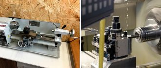
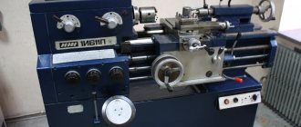
16B05A General view of a screw-cutting lathe
Photo of screw-cutting lathe 16B05a
Photo of screw-cutting lathe 16B05a
Photo of screw-cutting lathe 16B05a
Photo of screw-cutting lathe 16B05a
Specifications
One of the main features of the 16U04P screw-cutting lathe is stepless control of the spindle speed in forward and reverse directions, which is ensured by the use of a V-belt variator. Among the positive characteristics, the values of the maximum turning diameter and quill overhang are usually noted, and as a disadvantage, they indicate the small size of the spindle through hole. Main technical characteristics of 16U04P (linear dimensions in mm):
- height: center-to-center axis above the frame - 108, turning above the guides - 100, turning above the carriage - 59;
- center distance - 350;
- through hole in the spindle - Ø 20;
- quill stroke - 70;
- spindle speed range - 70÷3500 rpm;
- main drive power - 800 W.
- machine/stand weight - 360/390 kg;
In the 16U04P passports available for viewing, only one center-to-center distance size is indicated - 350 mm. However, it is absolutely known that the plant produced an extended modification of the lathe with an RMC of 450 mm.
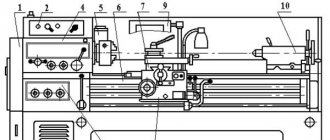
16B05A Arrangement of components of a screw-cutting lathe
Location of the main components of the screw-cutting lathe 16B05a
List of components of screw-cutting lathe 16B05A
- Bed - 16B05A.111.000
- Cabinet - 16B05A.121.000
- CVT - 16B05A.212.000
- Front headstock - 16B05A.221.000
- Guitar - 16B05A.311.000
- Feed box - 16B05A.321.000
- Apron - 16B05A.331.000
- Caliper - 16B05A.343.000
- Cooling - 16B04A.511.000
- Fencing - 16B04A.611.000
- Shield - 16B05A.621.000
- Hydrostatic unit - 16B04A.071.000
- Coolant pump unit - 16B04A.714.000
- Hydrocommunications - 16B04A.721.000
- Rear headstock - 16B05A.231.000
- Electrical equipment - 16B04A.811.000
- Switch - 16B05A.822.000
- Control and monitoring unit - 16B04A.715.000
Location of components
The delivery set of the 16U04P screw-cutting lathe includes the machine itself and a massive stand for its installation. In its left part on the lower frame there is a variator, in the right there is a cabinet with electrical equipment, and between them there is a coolant tank and an electric pump. On the upper surface of the cabinet there is a tray for collecting chips and cutting fluid. The coolant is drained into the tank through the sump filter. On the front top of the cabinet there is a machine control panel, next to which there is a drawer for tools. The cabinet is attached to the concrete floor with five anchor bolts.
In terms of the composition of the basic components, 16U04P is similar to other representatives of the family of universal turning equipment:
- bed;
- drive with variator;
- headstock;
- caliper;
- gearbox;
- guitar;
- apron;
- tailstock.
The 16U04P bed is a massive cast iron structure, which is secured to the stand with bolts. The undoubted advantages of this machine include a large through window in the bed, through which turning chips and coolant can easily fall onto the pallet. On its upper surface there are two pairs of guides: wide prismatic in the center, and narrow at the edges: flat and trapezoidal.
If you need metal mesh for concrete reinforcement, we recommend that you pay attention to the production of road mesh.
Central guides: the front headstock is installed on the left, the tailstock is installed on the right, and the lower carriage of the caliper is installed on the outer ones. A guitar with a snaffle is mounted on the headstock - a mechanism for changing the direction of the lead screw and moving its neutral position, and below there is a feed box, from which the movement is transmitted through the lead screw and the lead shaft to the apron and then to the caliper. The 16U04P caliper is traditional, cross-shaped, with two carriages and a cutting slide.
16B05A Location of controls for a screw-cutting lathe
Location of controls for screw-cutting lathe 16B05a
List of controls for screw-cutting lathe 16B05A
- 1. “Stop” button and spindle braking
- 2. Speed selector knob
- 3. “Start” button for direct spindle rotation
- 4. “Start” button for spindle reverse rotation
- 6. Thread pitch increasing link handle
- 7. Feed drive reverse handle
- 9. Handle for switching feeds and threads
- 10. Feed and thread switching handle
- 11. Handle for turning on the lead screw or lead shaft
- 12. Handle for switching feeds and threads
- 13. Handle for switching feeds and threads
- 14. CVT gear shift knob
- 16. Handwheel for changing spindle speeds
- 18. Handle for turning on the apron safety device
- 19. Handwheel for adjusting the amount of traction force
- 21. Handle for turning on the uterine nut
- 22. Button for switching longitudinal and transverse feed of the caliper
- 24. Handwheel for moving the tailstock quill
- 25. Tailstock clamp handle
- 26. Handle for moving the upper carriage
- 27. Tailstock quill clamp handle
- 29. Light switch
- 30. Tool holder clamp handle
- 31. Manual lateral movement handle
- 32. Handwheel for manual longitudinal movement
- 33. Button for turning on the handwheel and longitudinal feed dial
- 35. Cooling switch
- 38. Introductory machine
Location of controls
Top of the 16U04P cabinet: three buttons are located in a row: stop and brake, normal and reverse spindle rotation, and to the right of them there is a small speed control wheel and a variator shift lever. The left side surface of the cabinet is equipped with an automatic power supply and a switch for the pump of the tool cooling system.
On the machine itself, directly on the spindle assembly, there is a pull handle and a bit switch lever, and under them, on the feed box, there are two longitudinal feed switch handles. On the apron of the machine there is a steering wheel for manual longitudinal positioning and a handle for its activation, as well as a handle for mechanical longitudinal movement. Above it on the caliper there is a two-way rotating handle for manual transverse movement, and on the side of it is a positioning handle for the upper carriage. The tailstock is equipped with three controls: a mounting lever on the surface of the guides, as well as a steering wheel for extending the quill and a handle for clamping it.
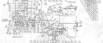
16B05A Kinematic diagram of a screw-cutting lathe and bearing arrangement
Kinematic diagram of a screw-cutting lathe 16B05a
The kinematic diagram of the machine allows the following operations:
- the main movement is spindle rotation
- feed movement - cutter movement
- rotation of the lubrication pump
16B05A Variator for screw-cutting lathe
Variator of screw-cutting lathe 16B05a
CVT (continuously variable gearbox)
The variator consists of the variator itself and a two-stage gearbox (range shift box).
The first (drive) shaft 2 of the variator is driven into rotation by a flanged electric motor through a gear coupling half. The second half of the coupling is made integral with shaft 2, on which a stationary (in the axial direction) disk 4 and a spring-loaded sliding disk 3 are installed, forming the variator drive pulley. From this pulley, rotation is transmitted through a wide V-belt to shaft 7 through the driven variator pulley, consisting of a fixed disk 5 and a controlled sliding disk 6.
In addition to the driven pulley, gears 8 and 9 are located on shaft 7. Gear 9 is equipped with an outer and inner ring gear and a half-coupling. Gear 8, moving along the splines along shaft 7, switches the speed ranges of the variator output shaft. The drive pulley of the V-belt drive, connecting the variator to the headstock, is mounted on this shaft. To tension the transmission, the housing 11 of the variator gearbox can be rotated on the glass 10, mounted on the housing 1 of the variator. The housing 11 is rotated using the coupling nut 21, after which the housing is secured with screws to the glass 10.
The control mechanism for the variator and gearbox is located on top of the variator body. Handwheel 12 controls the movement of sliding disk 6, handle 16 serves to switch gears in the gearbox. A planetary gear 20—19—18—17 connects the handwheel 12 with a disk 13, on which a ring 14 with a dial 15 is installed. There are two spindle speed scales on the dial, one for directly turning on the spindle, the second for turning on the spindle through overdrive.
To read the scales, two pairs of indicator strokes are used, printed on a transparent shield located above the dial. When switching variator speeds, the shield moves together with handle 16. For counting, use the pair of index strokes that is currently in the upper position.
16B05A Spindle head of screw-cutting lathe
Spindle head of screw-cutting lathe 16B05a
The headstock housing contains:
- spindle
- overkill
- drive of threads and feeds with bit
- control mechanism
The gear ratio of the headstock is 1/8. The control of the headstock 6, 7 and the direct clutch 10 is carried out with one handle. Next to the selection gear 11 on the spindle 4 there is a gear 3 for driving threads and feeds. The gear wheel 1, located on the first shaft 12 of the drive of threads and feeds, can be connected either to the gear wheel 11, or to the gear wheel 3 sitting on the spindle. This makes it possible to increase the thread pitch when enumeration is turned on.
Changing the direction of feed or cut thread is carried out by a snaffle consisting of a double gear wheel 13, a sliding gear wheel 15 and a parasitic wheel 16. The wheel 15 is seated on the splines of the output shaft 14, onto the end of which one of the replacement wheels of the guitar is put on.
The control handles for the headstock mechanisms are located on the front wall of the headstock. A cast casing is attached to the headstock body 5 in front, in which control buttons for the main electric motor are installed.
Lubrication of the headstock mechanisms is centralized, from a lubrication unit.
16B05A Feed box for screw-cutting lathe
Feed box for screw-cutting lathe 16B05a
The feed box of the machine (Fig. 6.6) in combination with the guitar allows you to set the required gear ratios for cutting threads with different pitches and obtaining different longitudinal and transverse feeds.
The feed box contains the following mechanisms:
- Main row mechanism (gears 1, 2, 3, 4, 18, 21, 22, 23)
- Multiplying mechanism (gears 5, 6, 14, 15, 16, 17, 26)
- Row shift mechanism (gears 19, 20, 22, 23)
- Mechanism for switching the transmission of motion to the lead shaft or to the lead screw (half-coupling 13, gears 11, 10, 9, 7)
- Mechanism for direct engagement of the lead screw (coupling halves 13, 17)
- Belt drive mechanism for fine feeds from a variator (pulley 24)
- Switching mechanism (not shown in figure)
The main series mechanism makes it possible to obtain four gear ratios proportional to the four pitches of metric or modular threads.
By multiplying these ratios by the multiplying gear ratios (1/4, 1/2, 1, 2) and by the row shifting gear ratios (1.1 1/4), metric and modular threads can be cut while constantly tuning the guitar.
The switching mechanisms are located on the plate under the feed box cover. The shift handles are located on the front cover.
Oil pressure from the unit is supplied to the front and rear support bearings and is regulated by two hydraulic pressure valves.
The hydrostatic unit also provides centralized lubrication of gears and bearings of the spindle head, feed box and variator.
Hydraulic system of machine 16B05a
The hydraulic system in the machine carries out:
- power supply for hydrostatic spindle supports;
- lubrication of gears of the headstock and gearbox;
- lubrication of variator gears;
- lubrication of gearbox gears.
16B05A machine consists of the following components and groups:
- hydrostatic unit;
- hydrocommunications;
- spindle load control unit.
The “Hydrostatic unit” group includes the following units:
- control and monitoring unit;
- pumping installation.
The “Hydrostatic unit” group is a complete installation, including a pumping unit, filtration, regulation and pressure control equipment.
Capabilities of screw-cutting lathes
Steel ball, completely manufactured on a 16B05a lathe
The photograph shows a steel ball that has been completely machined on a lathe.
From a solid workpiece, using a set of tools, it is possible to turn a ball in a ball , a cube in a cube in a cube and in a cube , a cube in a dodecahedron , which in turn is in a ball, a ring in a ring .
Overall dimensions of the workspace
The area of possible processing of turning equipment is determined by the maximum capabilities of its mechanisms directly involved in the processes of positioning and turning, as well as components and assemblies that limit their capabilities. The maximum turning length during turning is determined by the maximum center-to-center distance. The 16U04P lathe was produced with two RMC options: 350 and 450 mm. The maximum turning diameter above the guides and carriage is the same for both options and is 200 and 118 mm, respectively, and the maximum stroke of the transverse slide is 133 mm.
Main technical characteristics of the machine 16B05A
| Parameter name | 16M05A | 16B05A |
| Basic machine parameters | ||
| Accuracy class | A | A |
| The largest diameter of the workpiece processed above the bed, mm | 250 | 250 |
| The largest diameter of the workpiece installed above the bed, mm | 270 | |
| The largest diameter of the workpiece installed above the caliper, mm | 139 | 145 |
| Maximum length of the workpiece at centers (RMC), mm | 500 | 500 |
| Height of centers above flat bed guides, mm | 135 | 135 |
| The greatest distance from the axis of the centers to the edge of the tool holder, mm | 135 | 135 |
| Diameter of the workpiece installed in the chuck, mm | 5..160 | |
| Diameter of the workpiece installed in the collet, mm | 4..28 | |
| Diameter of the workpiece installed in the steady rest, mm | 5..50 | |
| Sample processing accuracy indicators: roundness, microns | 1,2 | |
| Roughness indicators for processing non-ferrous metal samples, microns | 0,04 | |
| Roughness indicators for processing steel samples, microns | 0,63 | |
| Productivity increase factor compared to the machine model 16B05A | 1,2 | |
| Spindle | ||
| Spindle hole diameter, mm | 32 | 26,5 |
| The largest diameter of the rod passing through the hole in the spindle, mm | 26 | |
| Spindle center according to GOST 13214-67 | Morse 4 | Morse 4 |
| Spindle end according to GOST 12593-72 | 4K | 4K |
| Number of speed steps for direct spindle rotation | b/s regulation | b/s regulation |
| Spindle direct rotation frequency, rpm | 25..2500 | 25..2500 |
| Spindle braking | There is | There is |
| Handle lock | ||
| Caliper. Submissions | ||
| Maximum longitudinal movement of the caliper, mm | 520 | 520 |
| Maximum lateral movement of the caliper, mm | 160 | 160 |
| Transverse movement of the caliper by one division of the dial, mm | 0,02 | 0,02 |
| Number of longitudinal feeds of the caliper | 28 | 28 |
| Number of cross feeds | 28 | 28 |
| Limits of longitudinal caliper feeds (in brackets - when using a pitch increasing link), mm/rev | 0,01..0,35 (0,01..2,8) | 0,01..0,35 (0,01..2,8) |
| Transverse caliper feed limits (in parentheses - when using a pitch increasing link), mm/rev | 0,005..0,175 (0,005..1,4) | 0,005..0,175 (0,005..1,4) |
| Steps of cut metric threads, mm | 0,2..28 | 0,2..28 |
| Steps of cut modular threads, mod | 0,1..14 | 0,1..14 |
| Steps of cut inch threads, threads per inch | 5..96 | 5..96 |
| Speed of rapid movements, mm/min | No | No |
| Cutting slide | ||
| Maximum length of movement of the cutting slide, mm | 150 | 150 |
| Movement of the cutting slide by one division of the dial, mm | 0,02 | 0,02 |
| Maximum angle of rotation of the cutting slide, degrees | ±45° | ±45° |
| Scale division of the tool slide rotation scale, deg | 1° | 1° |
| The largest cross-section of the cutter holder, mm | 16 x 16 | 16 x 16 |
| Height from the supporting surface of the cutter to the axis of the centers (cutter height), mm | 16 | 16 |
| Number of cutters in the cutting head | 4 | 4 |
| Tailstock | ||
| Quill diameter, mm | ||
| Tailstock quill hole cone according to GOST 2847-67 | Morse 3 | Morse 3 |
| Maximum movement of the quill, mm | 85 | 85 |
| Movement of the quill by one division of the dial, mm | 0,02 | 0,02 |
| Moving the quill by one ruler, mm | 1 | 1 |
| The amount of lateral displacement of the headstock body, mm | ±10 | ±10 |
| Electrical equipment | ||
| Number of electric motors installed on the machine | 3 | 3 |
| Main drive electric motor, kW | 1,5 | 1,5 |
| Hydraulic pump electric motor, kW | 2,2 | 0,75 |
| Coolant pump electric motor, kW | 0,12 | 0,12 |
| Total power of electric motors installed on the machine, kW | 3,82 | 2,37 |
| Dimensions and weight of the machine | ||
| Machine dimensions (length width height), mm | 1550 x 1350 x 1400 | 1530 x 910 x 1385 |
| Machine weight, kg | 1400 | 1365 |
- Extra high precision screw-cutting lathe 16B05A. Operating manual, Odessa, 1984
- High-precision screw-cutting lathes 16B04P, 16B05A. Operating manual, Odessa, 1976
- Acherkan N.S. Metal-cutting machines, Volume 1, 1965
- Denezhny P.M., Stiskin G.M., Thor I.E. Turning, 1972. (1k62)
- Denezhny P.M., Stiskin G.M., Thor I.E. Turning, 1979. (16k20)
- Batov V.P. Lathes., 1978
- Modzelevsky A. A., Muschinkin A. A., Kedrov S. S., Sobol A. M., Zavgorodniy Yu. P., Lathes, 1973
- Tepinkichiev V.K. Metal cutting machines, 1973
- Skhirtladze A.G., Novikov V.Yu. Technological equipment for machine-building industries, 1980
- Chernov N.N. Metal cutting machines, 1988
Bibliography:
Related Links. Additional Information
- Classification and main characteristics of turning
- Selecting the right metalworking machine
- Multi-start thread. Methods for cutting multi-start threads on a lathe
- Graphic signs for lathes
- Friction clutch of a screw-cutting lathe
- Methodology for checking and testing screw-cutting lathes for accuracy
- Directory of lathe manufacturing plants
- Directory of lathes
Home About the company News Articles Price list Contacts Reference information Interesting video KPO woodworking machines Manufacturers
I bought a pig in a poke, it turned out to be 16B05P
I have been looking for a machine for a garage for a long time, since the capabilities of the “Universal-2” machine have been lacking for a very long time, and the opportunity to buy and install a heavy machine has only appeared now. I was looking for a machine of the Izhey class 1i611p - RMC from 500, turning diameter from 250, but I didn’t want a very large “crocodile”. I liked the Hungarian E3N-01 with RMC 750, but I never got around to this machine, and the seller turned down a decent price.
When I saw an advertisement on Avito for the sale of a machine that was facing the wall, I initially mistook it for an E3N, which I happily informed the seller about. In response, I heard that the machine was domestic, especially precise, and its name was not known at all. I became curious and decided to go and look at the machine.
When I saw the machine, I liked it. Well, I just liked it, it happens. A fresh, not hackneyed machine. I also liked the fact that they gave the equipment with the machine - reamer, taps, dies, cutters and something else. When I saw WHAT they were giving away with the machine, I realized that I just needed to grab it before it was intercepted. I couldn't give away this pile of tools. I still remember how I ordered tools one at a time from different cities of our Motherland, but this machine, which was in pilot production, came with a lot of tools. Probably, like Vitaly107 - you can hang the entire ceiling with tools if you hang only drills and reamers individually. Plus some dies - a couple of buckets. I named the price, the seller was satisfied with it, and they shook hands. I went, withdrew money, found a manipulator with the help of the owner, persuaded me to work overnight and take the tool out of the city to the Moscow region, loaded the machine (1 ton according to the passport) and the tool (half a ton according to the sensations) into the body of the manipulator, brought it to my city, unloaded it and I was home at two o'clock in the morning.
I went and looked at the machine, damn it 
The machine turned out to be Kirovkan 16B05P. feed accuracy - 0.02 ("P"), bearings - roller and ball (without a high-pressure oil station, which is needed for a machine with the index "A"). In general, after the “Universal-2” the machine looks like a “Boeing” next to a “Zhiguli”. There are no tool holders, there are only a couple of replaceable modules from tool holders type 200-100, or whatever they are called. There are no gears.
There is still no steering wheel for selecting the variator speed and engine speed. Can anyone tell me where I can buy one or tell me the dimensions of the steering wheel? Maybe I'll make the steering wheel myself. Also, the cross feed handle is bent.
I would also be happy to meet with the owner of such a machine - to learn how to correctly turn on the feeds and so on - there are really a lot of handles.
Modified April 24, 2013 by hof