Information about the manufacturer of the screw-cutting lathe 1m63mf101
Manufacturer of the lathe model 1m63mf101 - Tbilisi Machine Tool Plant named after. CM. Kirov .
Machine tools produced by the Tbilisi Machine Tool Plant named after. Kirov
- 1D63A
- universal screw-cutting lathe Ø 615 - 1M63D
- universal screw-cutting lathe Ø 630 - 1M63M
universal screw-cutting lathe Ø 630 - 1М63МФ101
screw-cutting lathe with digital display Ø 630 - 9M14
– pipe cutting machine Ø 630
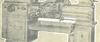
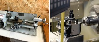
General view of the screw-cutting lathe 1m63mf101
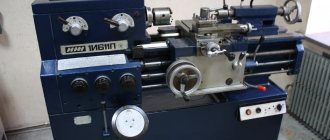
Photo of screw-cutting lathe 1m63Bf101
Photo of screw-cutting lathe 1m63mf101
Photo of screw-cutting lathe 1m63mf101
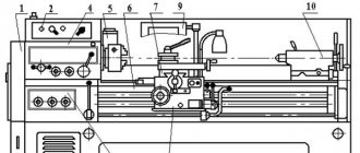
Location of the main components of the screw-cutting lathe 1m63mf101
Location of the main components of the screw-cutting lathe 1m63mf101
- Replacement gears - М63Б.08.000
- Front headstock - М63М.20.000
- Cartridge guard - М63Б.19.000
- Apron - М63М.60.000
- Caliper - М63М.40.000
- Electrical equipment - М63М.18.000
- Fencing – М63М.81.000
- Fencing – М63М.81.000
- Rear headstock - М63М.30.000
- Bed - М63М.16.000
- Electric motor - М63М.17.000
- Feed box - М63Б.70.000
- Protective casing - М63Б.95.000
- Movable steady rest - М63М.10.000
- Fixed steady rest - M63M.11.000
Location of controls for screw-cutting lathe 1m63mf101
Location of controls for screw-cutting lathe 1m63mf101
Controls of the 1m63mf101 screw-cutting lathe and their purpose
- Spindle speed setting handle
- Handle for setting normal and increased thread pitch and division into multi-start threads
- Handle for setting right and left threads and feeds
- Chuck guard lock button
- Spindle speed setting handle
- Handle of the plunger pump for lubrication of the guides of the longitudinal movement of the caliper and the lead screw
- Pull button for turning on the mechanical cross feed of the caliper
- Toggle switch for local lighting
- Pull button for turning on the mechanical cross feed of the caliper
- Handle for turning on the mechanical movement of the upper support (cutting slide)
- Handle for turning and fastening the cutting head
- Head for clamping and releasing the carriage fastening block
- Upper slide manual cross feed handle
- Button for enabling rapid movement (rapid strokes) of the caliper
- Toggle switch for turning cones and cylinders
- Cooling pump switch
- Remote control feed switch
- Tailstock quill fastening handle
- Tailstock quill movement flywheel
- Handwheel handle
- Clutch control handles
- Lead screw nut engagement handle
- Push-button stations for turning on and off the main drive
- Flywheel for manual longitudinal movement of the caliper
- Push-button stations for turning on and off the main drive
- Clutch control handles
- Adjustment handle for adjusting the thread pitch and turning off the rotation of the lead screw
- Adjustment handle for thread pitch and feed
- Thread selection knob
- Handle for selecting feed rates and thread pitch
- Pulley shaft square for dividing into multi-start threads
- Input switch
- Load indicator
- Signal lamp for turning on the electromagnetic brake
- Signal lamp for voltage presence
- Warning light - emergency
Kinematic diagram of a screw-cutting lathe 1m63mf101
Kinematic diagram of a screw-cutting lathe 1m63mf101
Bearing arrangement diagram for screw-cutting lathe 1m63mf101
Bearings for lathe spindle support 1M63MF101
The spindle of the 1M63MF101 machine is mounted on 2 bearings:
- 91. Front bearing No. 2-697928L angular contact roller, conical (with tapered rollers), double row, wide series.
- 90. Rear bearing No. 2-17722L angular contact roller, conical (with tapered rollers), single row.
Application area
The buyers of the 1M63 screw cutting machine were often machine-building plants with fairly large production volumes. This is due to the fact that the model’s lead screw allows processing of workpieces with a length of 750-10000 mm, depending on the RMC. However, today this screw-cutting lathe is significantly inferior to modern screw-cutting models in terms of productivity and processing accuracy. Purpose: you can sharpen cylindrical and cone-shaped parts, cut threads.
The 1M63 model lathe can be used to work with complex shapes and rounded types of workpieces. An additional purpose is cutting various standard threads. The equipment drawing assumes a very convenient design of the main spindle and the cutter itself; in addition, the following tools can be installed for operation: countersinks, drills, taps and dies. The workpiece itself for subsequent processing can be fixed directly in the chuck or supported by fasteners in the centers.
The main advantages of the machine are attributed to:
- ease of performing any operation;
- uncomplicated design of the machine's key elements;
- the bed of the 1M63 lathe is characterized by sufficient rigidity, and the standards of temperature stability and processing accuracy have also been increased;
- the characteristics of the installation’s engines have high power ratings, which facilitates metal processing;
- the wear resistance of each individual component unit is high;
- thread cutting speed is very high;
- the kinematic diagram is characterized by a certain rigidity, which has a positive effect on the overall performance of the installation;
- The 1M63 package includes electrical and standard mechanical interlocks, which provide maximum safety when performing any operation.
Description of the design of the main components of the screw-cutting lathe 1m63mf101
Gearbox for screw-cutting lathe 1m63mf101
Gearbox for screw-cutting lathe 1m63mf101
The gearbox is attached to the left head of the frame. Drive pulley 6 (Fig. 5) of the gearbox receives movement from the electric motor through a V-belt drive.
The regulation of the main movement mechanism is stepwise. The rotation of the pulley sets in motion a whole series of gearbox gears, by sequential switching of which you can obtain 24 spindle rotation speeds, two of which overlap. The spindle receives the highest six speeds directly from shaft 7, which contributes to a sharp increase in the efficiency of the machine when operating at high speeds, as well as a significant reduction in noise.
Setting certain spindle rotation speeds is carried out by moving gears along the shafts using two handles 2 and 1, located on the front of the gearbox. All gears are made of high-quality steel with appropriate heat treatment and sit on spline rollers rotating in ball and roller bearings. The front support of the steel hollow spindle 9 is a radial double-row adjustable roller bearing 10 with short cylindrical rollers, and the rear support is an angular contact ball bearing 4. The axial load on the spindle is perceived by a thrust ball bearing 3 located at the rear spindle support.
To start, stop and engage quick reverse, there is a friction plate clutch 5. The clutch is activated by handles located on the frame at the headstock and on the apron.
The spindle is braked automatically when the friction clutch is turned off using an electromagnetic clutch 8.
The gearbox contains mechanisms that make it possible to reverse the movement of the caliper and increase the pitch of the cut thread by 4 or 16 times.
Apron for screw-cutting lathe 1m63mf101
Apron for screw-cutting lathe 1m63mf101
Closed apron with removable front wall. The apron receives movement from the feed box through the lead screw when cutting threads or through the drive shaft when performing other work (Fig. 7).
Thanks to the presence of electromagnetic couplings 4 and 5, control of the apron is concentrated in one rotary handle 7, located on the right side of the apron. The direction of rotation of this handle coincides with the direction of the required feed movement or rapid movement of the carriage and cross slide. In this case, to ensure rapid movement, you must press button 6 located on the handle itself.
Thanks to the presence of an overrunning clutch 8 in the apron, it is possible to turn on the rapid speed when the working feed is turned on.
To prevent simultaneous activation of the lead screw and the lead shaft, an electrical interlock is provided.
The electric motor for fast movement of the caliper is located on the right side of the apron. On the front of the apron there is a longitudinal turning dial 2 with a division value of I mm. In order to eliminate the influence of the apron mechanism when cutting threads, the roller of the longitudinal feed rack and pinion gear is disconnected from this mechanism by pushing the pull button I located inside the roller, which disengages the internal clutch 3.
Circulating apron lubrication system
The system includes a reservoir 23, a plunger pump 17, an oil distributor 21. The plunger pump is driven by a cam mounted on the rack and pinion gear shaft. The oil is supplied by a pump to the oil distributor, from which it is supplied to lubricate the apron parts. The presence of lubrication in the system and its level in the apron are monitored using oil indicators 20 and 25. The operation of the plunger pump is monitored during accelerated movements of the caliper.
Feed box for screw-cutting lathe 1m63mf101
Feed box for screw-cutting lathe 1m63mf101
Feed box is closed type, biaxial. By switching the appropriate handles and, if necessary, installing replacement gears, you can configure the feed mechanism for cutting a normal range of metric, modular, inch and pitch threads, as well as to obtain the necessary feeds for turning (Fig. 8).
To cut precise and special threads, you can use direct engagement of the lead screw (this will require making a special set of gears).
Support for screw-cutting lathe 1m63mf101
Support for screw-cutting lathe 1m63mf101
The support of the cross design has longitudinal movement along the guides of the frame and transverse movement along the guides of carriage I (Fig. 6). Both movements can be manual or mechanical, and mechanical - working or accelerated. The rotating part of the caliper 2 has guides for moving the upper part of the caliper 4 with the cutting head 3.
The upper part of the caliper can also be moved manually and mechanically. The cross screw nut 6 has a device for taking out the backlash. The axial forces of the transverse screw and the screw of the upper slide are perceived by thrust ball bearings 5.
Replacement gear wheels of the machine 1m63mf101
The machine is supplied with a set of replaceable gears for producing metric and inch or modular and pitch threads. Replaceable gear wheels are located on the left wall of the gearbox housing. The machine is equipped with a protective casing covering the left wall of the gearbox.
Tailstock of the machine 1m63mf101
The tailstock is a smoldering rigid structure. After installation on the bed guides, the tailstock is secured to it using two strips and four bolts.
The movement of the tailstock along the bed is facilitated by four spring-loaded ball bearings mounted in the bridge. To determine the amount of movement of the quill during drilling operations, a dial is installed on the screw near the flywheel.
Machine rests 1m63mf101
The machine is equipped with movable and fixed rests for processing round parts with a diameter of 20 to 150 mm.
Cooling system of the machine 1m63mf101
From the electric pump installed in the right cabinet, the coolant flows through a hose through a pipeline on the support to the tool, and then flows into two troughs installed in front and behind the machine, from where it enters the tank of the right cabinet and to the electric pump.
The troughs and tank should be cleaned at least once a month.
Design Features
The 1M63 has several qualities that distinguish it from other lathes:
- The 1M63 tool holder is designed so that tools made of special alloys and high-speed steel can be used. The tool holder is designed in such a way that it can be adjusted to fit the cutting tool and rotated to the desired angle.
- The 1M63 metal lathe belongs to the class of screw-cutting machines, which are responsible for the ability to carry out work on cutting threads. To do this, a guitar of interchangeable gears is installed. In addition, the gearbox has replaceable gears. By selecting gears, you can change the thread pitch.
- In order for the part to be turned at high speed and at high feed rates, the rigidity of the lower part of the support and the bed was increased.
- The 1M63 screw-cutting lathe is equipped with a special motor and feed box, which make it possible to speed up the movement of the support while turning the workpiece. The feed box also has hardened steel gears.
- When creating the upper part of 1M63, the possibility of movement was also provided. That is why, when installing a standard tool holder, it is possible to turn conical surfaces.
Guitar lathe 1M63
The passport of the 1M63 screw-cutting lathe indicates that the weight varies from 4200-13200 depending on the RMC indicator. Let's also review the main characteristics.
Download the passport (operating instructions) of the 1M63 screw-cutting lathe
A wide range of work performed on turning equipment of this model is ensured by individual design upgrades. Any operation of turning, creating cones and cutting threads is carried out quite easily, without fine scrupulous adjustments. Additional design features of the 1M63 installation are:
- the diameter of the workpieces has been increased to 700 mm;
- the permissible diameter of parts above the caliper is 350 mm;
- the permissible weight of workpieces has been increased, now you can work with parts up to 3.5 tons;
- the diameter of the cylindrical hole in the main spindle is 105 mm;
- there is a function of cross-shaped displacement of the calipers in the longitudinal plane – 5.2, in the transverse plane up to 2 m/minute;
- the power of the power unit was increased to 15 kW;
- The weight of the model is 5750 kg.
Lathe support 1M63
Large dimensions and increased functionality allow the 1M63 model to be installed in large workshops, where the emphasis is on the quantity of products produced. At the same time, the accuracy and efficiency of the machine also remains at a sufficient level.
Adjustment of screw-cutting lathe 1M63MF101
During the operation of the machine, there is a need to regulate individual components of the machine in order to restore their normal operation.
Adjusting the friction plate clutches of the gearbox (Fig. 25)
Adjusting the friction clutches of the gearbox of the machine 1m63mf101
If slippage occurs, the friction clutches must be adjusted immediately, otherwise the increased friction will cause the discs to overheat and the clutch may fail. Adjustment of the friction clutches of both forward and reverse strokes is carried out using clamping nuts 1. The clamping nut can be rotated after the protruding hook 2 is recessed into the ring 3. The correctness of the adjustment is determined by the force of engagement of the clutches using the control handle 21 (see Fig. 6).
Access to the clutch is provided through a lockable window in the rear wall of the gearbox housing.
Simultaneously with adjusting the friction clutches, it is necessary to adjust the brake clutch control cam.
The acceleration time of a spindle with a three-jaw chuck Ø 400 mm at 1600 rpm with forward stroke should be 4...6.5 s, with reverse stroke 7...10 s. Checked at idle.
Under these conditions, the braking time should not exceed 10 seconds.
Aligning the spindle axis (Figure 26)
If the parallelism of the spindle axis relative to the frame guides is not correct, loosen all the bolts securing the gearbox to the frame, using screws 1 screwed into block 2, which is installed under the spindle head, align the spindle axis and tighten the fastening bolts.
Installing the tailstock quill axis (Fig. 27)
Transverse displacement of the tailstock is carried out when setting up for turning cones using screws 1, loosening one of them and tightening the other. When installing the tailstock coaxially with the axis of the headstock spindle, align the marks marked on the plates of the headstock body and the bridge at the right end.
Adjusting the tailstock support spring bearings (Fig. 28)
During operation or after repair, it may be necessary to regulate the degree of compression of the cylindrical springs 4 and 5 of the support spring-loaded bearings 6, mounted in the tailstock bridge in order to ensure ease of movement of the tailstock along the frame.
To do this you need:
- loosen the screws securing the headstock;
- Unscrew the top plugs 1 and, using screws 7, move the tailstock 2 along the bridge so as to gain access to the adjusting plugs 3. By turning the plugs, ensure that the headstock can easily move along the frame in the absence of a gap between the guides of the bridge and the bed.
Adjusting the gap in the cross slide guides (Fig. 29)
The gap between the guides of the carriage and the cross slide is adjusted by tightening the click 1 using two screws 2 located at both ends of the slide.
Adjusting the gap in the slide guides of the caliper (Fig. 30)
When a gap appears in the guides of the cutting slide, the wedge 1 is tightened with screw 3, after which the position is fixed with screw 2.
Eliminating the “backlash” of the caliper transverse movement screw (Fig. 31)
Elimination of backlash of the machine screw 1m63mf101
The “backlash” of the transverse support screw, which occurs when nuts 3 and 4 are worn, can be eliminated by turning worm 2 clockwise, for which it is necessary to first unscrew the locking screw 1. Adjustment is made if the handle lift exceeds 5 divisions of the dial.
Eliminating the “backlash” of the screw for moving the caliper tool slide (Fig. 32)
The “backlash” of the caliper tool slide screw, which occurs when half-nuts 4 and 5 are worn, can be eliminated by tightening screws 3, having previously loosened screws 1. Adjustment is made when the backlash of the handle exceeds 5 dial divisions. The adjustment is made through the threaded hole of the plug of 2 cutting slides, for which it is necessary to unscrew the plug and place the cutting slide in such a position that there is access to the adjusting screws.
Adjusting the axial clearance in the guide of the upper and lower halves of the lead screw nut (Fig. 33)
When a gap appears, the strip 1 is tightened with three screws 2 and secured with locknuts 3.
Adjusting the radial clearance between the lead screw and its nut (Fig. 34)
The amount of radial clearance between the lead screw 2 and the liners of its nut 1 is adjusted by screwing in or unscrewing screw 4 located under the apron. In the adjusted position, screw 4 is fixed with nut 3.
Coordination of the operation of the brake clutch with the operation of mechanical friction clutches (Fig. 3B)
To avoid failure of the electromagnetic brake clutch, it is necessary to check the position of cam 2 relative to the locking ball 1 and the limit switch located in the rear niche of the frame at least once a month.
With the friction clutch shift handle in a fixed middle position, the locking ball 1 and the pusher in the limit switch must be in the middle of their grooves. Regulation is carried out by installing the cam using screw 3.
At the same time, it is necessary to check the reliability of screws 4 and 5.
Adjusting the oil supply to the lead screw (Fig. 36)
Oil is supplied to the lead screw only when the lead screw is operating. To do this, you need to turn throttle 1 to open the gap to the required amount for oil to flow from the manual plunger pump.
Location of fittings for electromagnetic couplings of the apron and their regulation (Fig. 37):
- a brush holder that powers the electromagnetic clutch for the longitudinal movement of the carriage from right to left;
- a brush holder that powers the electromagnetic clutch for the longitudinal movement of the carriage from left to right;
- a brush holder that supplies the electromagnetic clutch for moving the cross slide and the upper support from the worker to the product;
- a brush holder that supplies the electromagnetic clutch for moving the cross slide and upper support from the product to the worker.
If the electromagnetic couplings of the apron fail to operate, it is necessary to turn off the machine and unscrew the brush holder of the faulty coupling.
Check the turned out brush holders for smooth movement of the brush in the holder, check the fit of the brush to the slip ring.
Adjusting the tension of the main drive belts (Fig. 38)
If a sensitive decrease in torque on the spindle is noticed with a normally adjusted friction clutch, the tension of the V-belt drive 2 of the main drive should be adjusted. To do this, it is enough to loosen four bolts 3 and rotate nut 1 to lower the main drive electric motor with plate 4 along the longitudinal grooves.
Secure the engine position by tightening all bolts 3.
Repair of equipment
Working on any equipment involves both scheduled and complex repairs. Measures to restore the functionality of individual mechanisms are required for the 1M63 model quite rarely. But a gradual loss of stability and loosening of individual structural components leads to a decrease in the accuracy of operations and a decrease in processing speed.
To carry out a comprehensive repair from the manufacturer, the customer must send the following documents together with the machine: a technical passport of the installation, special reports of previous technical inspections and a statement that reflects information about the assembly node modules.
Electrical equipment of screw-cutting lathe 1m63mf101
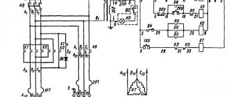
Electrical circuit diagram of screw-cutting lathe 1m63mf101
Electrical diagram of a screw-cutting lathe 1m63mf101
List of elements for the electrical circuit of the lathe 1m63mf101
Electrical equipment of a screw-cutting lathe 1m63mf101. General information
The electrical equipment of the machine operates at a voltage of 380 V and a frequency of 50 Hz.
The 110V AC control circuit is supplied from a step-down transformer.
The 24 V DC control circuits are powered from the rectifier bridge.
The voltage of the local lighting circuits is 24 V AC.
Alarm circuit voltage is 24 VDC.
Digital display device Ф5290
Digital display device Ф5290
Technical characteristics of digital display device Ф5290
The F5290 digital indication device (hereinafter referred to as the DRO) is designed to control linear or angular movements along one coordinate axis using a primary displacement transducer - the BS-155A selsyn (hereinafter referred to as the selsyn), indicating the position of the moving mechanisms of a machine tool or other machine in which it is applied and used as a specialized auxiliary component as part of information measuring systems, metalworking machines and other machines for measuring and controlling mechanical movements.
Areas of application: digital display systems.
F5290 digital indication devices (DID) are designed for processing electrical signals from primary measuring transducers and are used as specialized auxiliary components as part of information measuring systems, metalworking machines and other machines for measuring and controlling mechanical movements. The difference between the F5290 DRO and F5291 is that the F5290 DRO works with a selsyn-type displacement sensor, and the F5291 DRO works with a ruler-type or angular displacement sensor.
According to the main functional purpose, the DRO corresponds to type I according to GOST 27537.
The DRO provides:
The DRO provides automatic testing of the main components when the mains power is turned on.
The DRO provides an indication of the movement count in the range from minus 9999999 to plus 9999999 when monitoring linear movements, or from 0.00.00 to 359.59.59 when monitoring angular movements with an indication of the count in degrees, arc minutes and seconds, or from 0 to 359, or from 0.0 to 359.9, or from 0.00 to 359.99, or from 0.000 to 359.999 when monitoring angular movements with indication of the reading in degrees, tenths, hundredths, thousandths of a degree.
Unlike the 1M63M model machine, the 1M63MF101 machine is equipped with an F5290 digital display device.
The digital display device is installed above the gearbox and connected to a phase AC voltage of 220 V.
The feedback sensor is connected to the transverse lead screw and controls its rotation, located on the machine carriage and connected to the display unit via a flexible electrical connection.
The digital display device is powered from the control cabinet located on the headstock at the rear of the machine.
A digital display device (DDU) is designed to visually read the diameter of a part in digital form.
When the input machine is turned off, the DRO is de-energized.
The BS-155A selsyn sensor is connected to the digital display device with a flexible cable, and the sensor axis is connected to a transverse screw using a plate coupling.
The movement of the working tool by 5 mm corresponds to one revolution of the lead screw, and therefore the rotor of the BS-155A selsyn. The phase signal enters the display unit.
The digital readout on the unit’s indicator board, corresponding to one revolution of the synchronizer rotor, is 10 mm (i.e., double the movement—diameter) is automatically displayed.
The readout resolution of the DRO is 10 µm.
The instability of readings does not exceed ±2 µm.
Application of digital display device F5290
In the 1M63MF101 machine with a digital display device, it is recommended to use a combined mode for metalworking: ensuring the necessary manual movements using the DRO with the simultaneous use of universal measuring instruments.
In combined mode, the following submodes are possible:
- a) combined mode with constant use of universal measuring instruments. When processing all elements of a product, even with one tool, during a preliminary pass, the size of the product is determined for each element, and the movement to remove the allowance is carried out using the DRO;
- b) combined mode with one-time use of universal measuring instruments.
When processing all elements of a product, the size of the product is determined by one element, and the movement for processing the remaining elements is carried out using the DRO.
Carrying out measurements in metalworking using a DRO can be implemented in two ways.
The diameter measured by the universal instrument using decade switches is entered on the front panel of the device, then by pressing the “Record” key located there, it is recorded on the display. Next comes the metalworking process with observation of the current diameter using the DRO in an absolute coordinate system, where the zero point will be the spindle axis.
After measuring the diameter of the test pass with a universal measuring tool, the worker calculates the allowance that needs to be removed. It is defined as the difference:
Allowance = D meas. -d
Where:
D meas. - measured diameter,
d is the diameter of the finished part.
The worker enters the allowance into the DRO in the manner described in the previous subparagraph; Next, the part is processed until zero readings are shown on the device display for all digits.
In order to increase the processing accuracy, it is recommended to bring the cutting tool to the cutting point in the direction of the intended cutting, since it is necessary to select the backlash of the lead screw.
Main characteristics
The design of the clutch of the 1M63 lathe, as well as its other elements, complies with the established standards in 1982. The model belongs to accuracy class H and must meet the established standards. The technical specifications are as follows:
- 1M63 spindle bearings support rotation speeds ranging from 10 to 1,250 rpm.
- A lathe can have a very different RMC. During operation, both fixing elements are motionless.
- The model can be used for processing long and non-rigid parts with different RMC values. For this purpose, it is possible to install a steady rest. However, it is worth considering that the steady rest is not supplied. The steady rest for the 1M63 lathe is used to limit the deformation of parts when processing.
- The tool holder is made in a classic style: the tool itself is stationary, only the support moves. The distance between the axis of the centers and the edge of the tool holder is 32 cm. In the manufacture of the tool holder, durable material is used, which eliminates the possibility of deformation of the structure. Adjusting the tool holder allows you to select optimal turning performance.
- The holes in the spindle are 65 mm. The spindle is used to install workpieces with a diameter of 630 mm. A straight rod can be installed and fed as it is turned on the 1M63 screw-cutting lathe in question.
- The tailstock is installed on the screw-cutting lathe in question, and with its power, the rear end is fixed.
- The gearbox allows you to adjust the speed in 22 ranges.
- The support has longitudinal and transverse feed in automatic mode.
- The kinematic mechanism is quite complex. There is a front and back stock. There is a gearbox in the headstock. The tailstock allows you to fix the second end of the part. The position of the tailstock can be changed. Overrunning clutches 1M63 are also used, which are responsible for maintaining the accuracy of operation.
- When considering gearboxes and feeds, we note their high strength and reliability. The maintainability of the boxes makes the 1M63 screw-cutting lathe more attractive.
- The electrical cabinet is located in the headstock, which is confirmed by the drawing of the 1M63 lathe.
- The apron of the 1M63 lathe is controlled using a special switch.
- The characteristics of the replacement wheels allow you to cut inch, metric, modular and pitch threads. The technical potential of the model is quite large. You can install replaceable wheels for turning threads of various types
You should purchase a steady rest to improve the quality of processing when you need to carry out high-precision turning of deformable workpieces. Lunettes can be made from a wide variety of materials. If you do not use a steady rest, a strong feed will lead to deformation of the workpiece. Steady rests can be installed and removed depending on the tasks assigned.
Technical characteristics of the universal lathe 1m63mf101
| Parameter name | 1m63f101 | 1m63Bf101 | 1m63Mf101 |
| Basic technical data of the machine | |||
| Accuracy class according to GOST 8-82 | N | N | N |
| The largest diameter of the workpiece processed above the bed, mm | 630 | 630 | 630 |
| The largest diameter of the workpiece processed above the support, mm | 350 | 350 | 350 |
| Center height, mm | 315 | 315 | 315 |
| Maximum length of the installed RMC part, mm | 1400 | 2800 | 1500 |
| The greatest distance from the axis of the centers to the edge of the tool holder, mm | 320 | 320 | 335 |
| Maximum processing length of a part (without rearranging the cutting slide), mm | 1260 | ||
| Height of the cutter installed in the tool holder, mm | 32 | 32 | 32 |
| Maximum mass of the workpiece, kg | 2000 | ||
| Spindle | |||
| Spindle forward/reverse rotation frequency, rpm | 10…1250 18…1800 | 10…1250 18…1800 | 12,5..1600 22,4..2240 |
| Number of forward/reverse spindle speeds | 22/ 11 | 22/ 11 | 22/ 11 |
| Spindle hole diameter, mm | 70 | 70 | 80 |
| Center in the spindle according to GOST 13214-79 | Morse 6 | Morse 6 | Morse 6 |
| Spindle end according to GOST 12593-72 | 8m | 8m | 8m |
| Spindle inner taper size | Metric 80 | Metric 80 | Metric 100 |
| Maximum torque on the spindle, kNm | 3,3 | ||
| Spindle braking | There is | There is | There is |
| Caliper. Submissions | |||
| Maximum longitudinal/transverse movement, mm | 1260/ 400 | 2520/ 400 | 1360/ 400 |
| Number of feeds of longitudinal/transverse/cutter slide | 44/ 44/ 44 | 32/ 32/ 32 | 32/ 32/ 32 |
| Limits of working feeds of longitudinal/transverse/cutting slides, mm/rev | 0,064-1,025 0,026-0,38 0,028-0,34 | 0,06-1,4 0,024-0,518 0,019-0,434 | 0,06-1,4 0,024-0,518 0,019-0,434 |
| Limits of increased feed rates of longitudinal/transverse/cutter slides, mm/rev | 1,07-3,2 0,039..1,18 0,336..1,0 | 0,24-5,6 0,096-2,072 0,076-1,736 | |
| Limits/number of pitches of metric threads, mm | 1-192/ 56 | 1-224 | 1-224/ 46 |
| Limits/number of pitches of inch threads, threads/inch | 24-0,25/ 33 | 56-0,25 | 28-0,25/ 31 |
| Limits/number of modular thread pitches, module | 0,5-48/ 55 | 0,5-112 | 0,25-56/ 37 |
| Limits/number of pitch thread pitches, diametric pitch | 96-7/8/ 52 | 112-0,5 | 112-0,5 /30 |
| Speed of rapid movements longitudinal/transverse, m/min | 4,5/ 1,6 | 4,5/ 1,6 | 4,5/ 1,6 |
| Maximum cutting force allowed by the feed mechanism, kN | 2,22 | 2,22 | |
| The price of dividing the dial for longitudinal/transverse movement by diameter, mm | 1/ 0,05 | 1/ 0,05 | 1/ 0,05 |
| Movement per dial revolution during longitudinal/lateral movement, mm | 300/ 5 | 300/ 5 | 300/ 5 |
| Cutting slide | |||
| Maximum movement of the cutting slide, mm | 220 | 220 | 220 |
| Maximum angle of rotation of the cutting slide, degrees | ±90° | ±90° | ±90° |
| The cost of dividing the dial when moving the cutting slide, mm | 0,05 | 0,05 | 0,05 |
| Displacement per revolution of the dial when moving the cutting slide, mm | 5 | 5 | 5 |
| Tailstock | |||
| Maximum movement of the quill, mm | 240 | 240 | 240 |
| Transverse displacement of the tailstock, mm | ±10 | ±10 | ±10 |
| Cone for center in quill | Morse 5 | Morse 5 | Morse 5 |
| Digital display device (DRO) | |||
| DRO model | F5071 | F5071 | F5290 |
| Sensor type | Selsin BS-155A | Selsin BS-155A | Selsin BS-155A |
| Displacement measurement range, mm | 0,01…9999,99 | 0,01…9999,99 | 0,01…9999,99 |
| Readout resolution, µm | 10 | 10 | 10 |
| The instability (temporary drift) of the block readings together with the synchro does not exceed, µm | ±2 | ±2 | ±2 |
| The mass of the digital display does not exceed, kg | 8 | 8 | 5 |
| Electrical equipment of the machine | |||
| Number of electric motors on the machine | 3 | 3 | 3 |
| Main motion electric motor, kW (rpm) | 13 (1460) | 15 (1460) | 18,5 (1465) |
| Electric motor for fast movements, kW (rpm) | 1,1 (1400) | 1,1 (1400) | 1,1 (1400) |
| Coolant pump electric motor, kW (rpm) | 0,12 (2800) | 0,12 (2800) | 0,12 (2800) |
| Dimensions and weight of the machine | |||
| Machine dimensions (length, width, height), mm | 3530 x 1680 x 1290 | 4950 x 1780 x 1550 | 3655 x 1590 x 1420 |
| Machine weight, kg | 4300 | 5620 | 4400 |
- Screw-cutting lathes models 1m63m and 1m63mf101. Operating manual, Tbilisi, 1983
- Acherkan N.S. Metal-cutting machines, Volume 1, 1965
- Batov V.P. Lathes, 1978
- Beletsky D.G. Handbook of a universal turner, 1987
- Denezhny P.M., Stiskin G.M., Thor I.E. Turning, 1972. (1k62)
- Denezhny P.M., Stiskin G.M., Thor I.E. Turning, 1979. (16k20)
- Modzelevsky A. A., Muschinkin A. A., Kedrov S. S., Sobol A. M., Zavgorodniy Yu. P., Lathes, 1973
- Pikus M.Yu. A mechanic's guide to machine repair, 1987
- Skhirtladze A.G., Novikov V.Yu. Technological equipment for machine-building industries, 1980
- Tepinkichiev V.K. Metal cutting machines, 1973
- Chernov N.N. Metal cutting machines, 1988
Bibliography
Related Links. Additional Information
- Classification and main characteristics of turning
- Selecting the right metalworking machine
- Multi-start thread. Methods for cutting multi-start threads on a lathe
- Graphic signs for lathes
- Friction clutch of a screw-cutting lathe
- Methodology for checking and testing screw-cutting lathes for accuracy
- Directory of lathe manufacturing plants
- Directory of factories producing metal-cutting machines
- Directory of lathes
Home About the company News Articles Price list Contacts Reference information Interesting video KPO woodworking machines Manufacturers
Specifications
- The height of the centers is 31.5 cm;
- Dimensions: length - 3.53 m,
- width - 1.68 m,
- height - 1.29 m;
- main - 13 kW,
- main - 1460 rpm,
- bed - 63 cm,
- bed - 70 cm,
- direct rotation - 10-1250 per minute,
- longitudinal - 126 cm,
- metric - from 1 to 192 mm,
- metric - 56,
- in the longitudinal direction - 4500 mm/min,