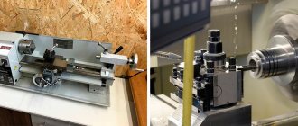
Device mechanisms
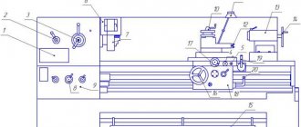
Universal lathes consist of mechanisms and standard units, which include :
- The lead screw is the main element of the device, which distinguishes it from a simple turning model.
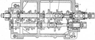
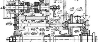
- A box that provides change and choice of feeds.
- Device apron. It converts the rotation of the roller or screw into the translational movement of the support with the tool.
- Running roller.
- Gear guitars. This is a module that is necessary to transmit rotational motion from one machine unit to another.
- Equipment cabinets. They act as supports. Thanks to them, the main control units of the equipment and the element being processed are at a convenient height for visual inspection.
- Electrical equipment.
- The spindle is the main component of a lathe. It clamps the workpiece and rotates with it. In this case, the cutting tool moves in two independent coordinates - across and parallel to the axis of rotation. The more powerful the spindle design and its wired motor are, the higher the equipment’s performance in terms of the speed of removing metal chips from the workpiece and the more massive the elements it can process.
- Bearing frame. All equipment mechanisms are mounted on it.
- A box that provides speed control.
- Back and front headstock. The headstock is a unit of turning equipment that is necessary to rotate and support the element being processed. The tailstock is needed to support the other end of the element being processed. Can be used to install a tap, reamer, drill and other tools.
- The machine support is necessary to secure the cutting tool and transmit feed movements to it. It includes carriages - lower slides that move along the bed guides. Transverse slides move perpendicular to the axis of rotation of the element along the guides of the lower slide, on which the tool carriage and tool holder are located. The cutting carriage can be rotated to the axis of rotation of the element at different angles.
A characteristic feature of this equipment is that the structural elements of different models have the same name and location. Machines in this category, which are produced by different manufacturing plants, are almost identical in design (including those with numerical control).
To control working systems, lathes are equipped with various levers and handles. In particular, these include:
- Control element for the direction of spindle movement and its stop.
- The element that is responsible for fixing the tailstock.
- Control element for caliper movement parameters.
- Feed parameters control body.
- The steering wheel is responsible for the movement of the quill.
- An element that is responsible for automatically starting the longitudinal feed and fixing the quill.
- Switching off and on the main engine.
- A control for selecting the direction of the thread to be cut.
- Control element for turning off and on the rotation of the lead screw.
- A handle that is designed to control the upper slide.
- A control element that determines the direction of movement of the slide (transverse or longitudinal).
- The handle that is responsible for selecting the thread pitch category.
- A control element that is responsible for selecting the parameters of the thread being cut (feed or pitch).
- A handle used to change the spindle rotation speed.
Processing schemes on standard metal-cutting machines
Processing schemes on standard metal-cutting machines
Turning schemes
Basic shaping movements: rotation of the part and translational movement of the tool. There may be several schemes depending on the equipment used.
Depending on the level of mechanization and automation, lathes are divided into:
- single-spindle lathes - universal, turret, hydrocopying,
— multi-spindle: horizontal turning, vertical turning.
Let's consider processing schemes on universal machines
when processing NCP.
1. In a three-jaw chuck (two options) at l/ d
≤3.
Option 1: used in single production (Fig. 11, a
).
Option 2: used on customized machines for serial and mass production (Fig. 11, b
).
a) b)
Rice. 11. Processing schemes on universal machines when processing NCP in a three-jaw chuck: a
– the part is oriented in the radial direction, but not in the axial direction:
1
– part,
2
– fixture,
3
– tool;
b
– the part is oriented in both radial and axial directions
2. Schemes for processing a part in a chuck with preloading by the rear center at 3< l
/d£5 (Fig. 12).
a) b)
Rice. 12. Schemes for processing a part in a chuck with preloading at the rear center: a
– in single production;
b
– serial and mass production;
4
– rear center
3. Scheme of processing a part in centers at 5< l
/
d
£ 10 (Fig. 13).
a) b)
Rice. 13. Schemes for processing parts in centers: a
– using a rigid front center;
b
– using a floating front center;
5
– driving device
4. Scheme of processing a part in the centers using a steady rest at l
/d > 10 (Fig. 14).
Rice. 14. Scheme of processing a part in the centers using a steady rest
The cartridges can be:
a) three-jaw self-centering;
b) two- and four-jaw non-self-centering. Used in single production. When installed in them, the part is verified.
When processing the outer cylindrical surfaces of a part, mandrels are often used. The mandrels can be rigid or expandable. Processing schemes are shown in Fig. 15.
a) b)
Rice. 15. Schemes for processing a part on a mandrel: a
– on a rigid frame;
b
– on an expanding mandrel;
1
– part,
2
– mandrel,
3
– rod;
4
– spindle;
5
– collet bushing
A part on a rigid mandrel can be installed with a gap, without a gap and with an interference fit.
Schemes of processing on turret lathes.
Turret lathes can have a turret head with a vertical axis of rotation (VOV) and with a horizontal axis of rotation (HOV).
The part can be processed from a rod or from a piece workpiece. When processing a part from a rod, its orientation in the axial direction is made along the right end along the stop (Fig. 16, a
), when processing a part from a piece workpiece - along the left end (Fig. 16,
b
).
The part is installed when processing from a rod in a collet chuck (Fig. 16, a
), when processing a piece workpiece in a three-jaw chuck (Fig. 16,
b
).
a) b)
Rice. 16. Layout diagram for processing a part on a machine with a WWII turret head and installing the part: a
– in a collet chuck;
b
– in a three-jaw chuck
The main movements are rotation of the part and translational movement of the tool; longitudinal feed is carried out by the turret. Transverse feed on machines with VOV RG is a transverse slide, on machines with GOV RG - a turret, and the feed will be circular. The execution of positions on a turret lathe is carried out sequentially. The turret and cross slide can work in parallel.
Processing diagrams indicating the tool at the end of the working stroke are drawn for each working position separately. For example, when processing a piece workpiece in a chuck (Fig. 17).
| Pos. I | Pos. II |
a) b)
Rice. 17. Processing schemes for installing a part in a chuck: a
– first working position;
b
– second working position
On machines with VOV RG it is possible to perform four…six positions, on machines with GOV RG – 12…16 positions. Basic processing methods: turning, facing, drilling, countersinking, reaming, grooving, threading.
Scheme of processing on a hydrocopying machine.
The installation pattern is in the centers, the front center is always floating.
From a longitudinal support, several cylindrical surfaces are processed with one cutter. The ends and grooves are trimmed from the transverse support (see Fig. 18, a
).
Scheme of processing on a multi-cutter lathe.
Installation schemes: in the centers, in the chuck, in the chuck with rear center clamping.
Several turning cutters are installed on the longitudinal and transverse supports (Fig. 18, b
). The main processing methods: turning of the NC and cutting the ends of the NC.
a) b)
Rice. 18. Processing schemes: a
– on a hydrocopying machine;
b
– on a multi-cutter lathe
Schemes of processing on a horizontal multi-spindle lathe.
Multi-spindle horizontal lathes can be four-, six-, or eight-spindle.
Rice. 19. Layout diagram of processing on a horizontal four-spindle machine: 1
– fixture,
2
– tool,
3
– workpiece
a) b)
Rice. 20. Workpiece installation diagrams:
A
– for piece workpieces;
b
– when processing from a rod
Each working spindle rotates at the same frequency. For all tools – one longitudinal feed. The installation position is non-working; the working positions have transverse supports. To change the position of the part, the spindle head rotates.
Processing diagrams on such machines are drawn for each working position (the same as on a turret lathe).
Basic processing methods: turning, trimming, drilling, countersinking, reaming, threading, grooving.
Schemes of processing on a vertical multi-spindle lathe.
Multi-spindle vertical lathes can be four-, six-, or eight-spindle.
a) b)
Rice. 21. Layout of processing on a vertical six-spindle machine:
A
– single index;
b
– two-index;
1
– device;
2
– tool; 3 – detail
There is one support at each working position. This support can be made in three varieties: the first provides longitudinal feed (vertical), the second – transverse feed (horizontal), the third – both vertical and horizontal feeds. The latest type of caliper provides only rough processing, so it is used only when absolutely necessary. Installation scheme: in a chuck or in a special device such as a chuck, piece workpieces. These machines may have one or two mounting positions. Basic methods: turning, facing, boring, reaming. Processing diagrams on a vertical multi-spindle lathe are drawn for each working position. For a single-index machine, the first position is installation, the others are working. Examples of processing schemes are shown in Fig. 22.
| Pos. I | Pos. II | Pos. III |
Rice. 22. Schemes of processing on a vertical multi-spindle lathe: pos. I – installation; pos. II – working position with transverse (horizontal) supply of tools; pos. III – working position with longitudinal (vertical) feeding of tools
Machining on CNC lathes
. Basic methods: turning, facing, drilling, countersinking, reaming, boring, threading. Processing takes place in a coordinate system. These machines are equipped with special tool holders or turret heads, and tool change is automatic.
Rice. 23. Scheme of processing on a CNC lathe
Rice. 30. Scheme of processing a part on a CNC vertical milling machine
Such machines can process planes, ledges, grooves and shaped contours. The tool is changed manually. The processing scheme with one tool and one installation of the part is rational. The main processing method is milling.
Rice. 33. Scheme of processing on a CNC drilling machine
CNC drilling machines with turret head.
Tool change is performed automatically. Such machines are used in mass production (Fig. 34).
Rice. 34. Layout diagram of processing on a CNC drilling machine with a turret head
Processing diagrams are drawn in the same way as when processing on conventional CNC drilling machines, but taking into account processing positions.
Rice. 36. Scheme of processing on an aggregate boring machine
Rice. 40. Scheme of processing a hole by broaching
When pulling a hole, the part is not fixed; it is only supported by a special device - a cradle. During processing, the part self-aligns along the broach.
Processing schemes on standard metal-cutting machines
Turning schemes
Basic shaping movements: rotation of the part and translational movement of the tool. There may be several schemes depending on the equipment used.
Depending on the level of mechanization and automation, lathes are divided into:
- single-spindle lathes - universal, turret, hydrocopying,
— multi-spindle: horizontal turning, vertical turning.
Let's consider processing schemes on universal machines
when processing NCP.
1. In a three-jaw chuck (two options) at l/ d
≤3.
Option 1: used in single production (Fig. 11, a
).
Option 2: used on customized machines for serial and mass production (Fig. 11, b
).
a) b)
Rice. 11. Processing schemes on universal machines when processing NCP in a three-jaw chuck: a
– the part is oriented in the radial direction, but not in the axial direction:
1
– part,
2
– fixture,
3
– tool;
b
– the part is oriented in both radial and axial directions
2. Schemes for processing a part in a chuck with preloading by the rear center at 3< l
/d£5 (Fig. 12).
a) b)
Rice. 12. Schemes for processing a part in a chuck with preloading at the rear center: a
– in single production;
b
– serial and mass production;
4
– rear center
3. Scheme of processing a part in centers at 5< l
/
d
£ 10 (Fig. 13).
a) b)
Rice. 13. Schemes for processing parts in centers: a
– using a rigid front center;
b
– using a floating front center;
5
– driving device
4. Scheme of processing a part in the centers using a steady rest at l
/d > 10 (Fig. 14).
Rice. 14. Scheme of processing a part in the centers using a steady rest
The cartridges can be:
a) three-jaw self-centering;
b) two- and four-jaw non-self-centering. Used in single production. When installed in them, the part is verified.
When processing the outer cylindrical surfaces of a part, mandrels are often used. The mandrels can be rigid or expandable. Processing schemes are shown in Fig. 15.
a) b)
Rice. 15. Schemes for processing a part on a mandrel: a
– on a rigid frame;
b
– on an expanding mandrel;
1
– part,
2
– mandrel,
3
– rod;
4
– spindle;
5
– collet bushing
A part on a rigid mandrel can be installed with a gap, without a gap and with an interference fit.
Schemes of processing on turret lathes.
Turret lathes can have a turret head with a vertical axis of rotation (VOV) and with a horizontal axis of rotation (HOV).
The part can be processed from a rod or from a piece workpiece. When processing a part from a rod, its orientation in the axial direction is made along the right end along the stop (Fig. 16, a
), when processing a part from a piece workpiece - along the left end (Fig. 16,
b
).
The part is installed when processing from a rod in a collet chuck (Fig. 16, a
), when processing a piece workpiece in a three-jaw chuck (Fig. 16,
b
).
a) b)
Rice. 16. Layout diagram for processing a part on a machine with a WWII turret head and installing the part: a
– in a collet chuck;
b
– in a three-jaw chuck
The main movements are rotation of the part and translational movement of the tool; longitudinal feed is carried out by the turret. Transverse feed on machines with VOV RG is a transverse slide, on machines with GOV RG - a turret, and the feed will be circular. The execution of positions on a turret lathe is carried out sequentially. The turret and cross slide can work in parallel.
Processing diagrams indicating the tool at the end of the working stroke are drawn for each working position separately. For example, when processing a piece workpiece in a chuck (Fig. 17).
| Pos. I | Pos. II |
a) b)
Rice. 17. Processing schemes for installing a part in a chuck: a
– first working position;
b
– second working position
On machines with VOV RG it is possible to perform four…six positions, on machines with GOV RG – 12…16 positions. Basic processing methods: turning, facing, drilling, countersinking, reaming, grooving, threading.
Scheme of processing on a hydrocopying machine.
The installation pattern is in the centers, the front center is always floating.
From a longitudinal support, several cylindrical surfaces are processed with one cutter. The ends and grooves are trimmed from the transverse support (see Fig. 18, a
).
Scheme of processing on a multi-cutter lathe.
Installation schemes: in the centers, in the chuck, in the chuck with rear center clamping.
Several turning cutters are installed on the longitudinal and transverse supports (Fig. 18, b
). The main processing methods: turning of the NC and cutting the ends of the NC.
a) b)
Rice. 18. Processing schemes: a
– on a hydrocopying machine;
b
– on a multi-cutter lathe
Schemes of processing on a horizontal multi-spindle lathe.
Multi-spindle horizontal lathes can be four-, six-, or eight-spindle.
Rice. 19. Layout diagram of processing on a horizontal four-spindle machine: 1
– fixture,
2
– tool,
3
– workpiece
a) b)
Rice. 20. Workpiece installation diagrams:
A
– for piece workpieces;
b
– when processing from a rod
Each working spindle rotates at the same frequency. For all tools – one longitudinal feed. The installation position is non-working; the working positions have transverse supports. To change the position of the part, the spindle head rotates.
Processing diagrams on such machines are drawn for each working position (the same as on a turret lathe).
Basic processing methods: turning, trimming, drilling, countersinking, reaming, threading, grooving.
Schemes of processing on a vertical multi-spindle lathe.
Multi-spindle vertical lathes can be four-, six-, or eight-spindle.
a) b)
Rice. 21. Layout of processing on a vertical six-spindle machine:
A
– single index;
b
– two-index;
1
– device;
2
– tool; 3 – detail
There is one support at each working position. This support can be made in three varieties: the first provides longitudinal feed (vertical), the second – transverse feed (horizontal), the third – both vertical and horizontal feeds. The latest type of caliper provides only rough processing, so it is used only when absolutely necessary. Installation scheme: in a chuck or in a special device such as a chuck, piece workpieces. These machines may have one or two mounting positions. Basic methods: turning, facing, boring, reaming. Processing diagrams on a vertical multi-spindle lathe are drawn for each working position. For a single-index machine, the first position is installation, the others are working. Examples of processing schemes are shown in Fig. 22.
| Pos. I | Pos. II | Pos. III |
Rice. 22. Schemes of processing on a vertical multi-spindle lathe: pos. I – installation; pos. II – working position with transverse (horizontal) supply of tools; pos. III – working position with longitudinal (vertical) feeding of tools
Machining on CNC lathes
. Basic methods: turning, facing, drilling, countersinking, reaming, boring, threading. Processing takes place in a coordinate system. These machines are equipped with special tool holders or turret heads, and tool change is automatic.
Rice. 23. Scheme of processing on a CNC lathe
Equipment classification
The types of this equipment are divided based on several parameters, which include:
- The maximum diameter of this part.
- The maximum length of a part that can be processed on this equipment.
- Weight of equipment.
The length of the part that is processed on this equipment of one model or another completely depends on the distance between its centers. When considering the diameter of the workpiece that a certain type of lathe can process, this parameter ranges from 100 to 4 thousand millimeters. It is also necessary to take into account the fact that equipment models that can process elements of the same diameter may have different lengths of the processed workpiece.
Universal lathes can have different weights. According to this parameter, equipment is divided into the following categories:
- Lightweight machines. Their weight does not exceed 0.5 tons. It processes elements with a diameter of 100-200 millimeters.
- The weight of the equipment does not exceed 4 tons. The permissible diameter of processing elements is 250−500 millimeters.
- Equipment weight up to 15 tons. The diameter of the processed elements ranges from 600-1250 millimeters.
- The machines are heavy. Their weight can reach 400 tons. The diameter of the processed elements is 1600-4000 millimeters.
Types of chips during turning
The technology for using a lathe involves removing the top layer from the workpiece, resulting in the formation of chips:
- fused - in the form of long sections of a twisted spiral, typical for high-speed processing of lead, copper, tin, and steel workpieces;
- elementary - represents short fragments that separate from the product in jerks, the result of working with parts made of low-viscosity and hard materials at low speed;
- fracture - small pieces scattering in different directions, appears as a result of processing metal with weak plastic properties;
- stepped - is a layered material reminiscent of stair steps, work is carried out at medium speed using parts made of medium-hard steel or aluminum alloys.
Chips are a natural waste product of the turning process. The chemical properties of the metal from which it consists are not affected, so it can be used for re-melting.
During turning work, it is important to ensure the timely removal of chips from the working surface. When using specialized turning equipment, this function is implemented automatically.
Performers from Moscow
There are many enterprises in Russia that are engaged in metal processing and can offer high-precision, high-quality turning and screw-cutting processing on favorable terms and at an affordable cost.
Thanks to their special production conditions, it is possible to process large batches and carry out large-scale as well as piece orders, taking into account the agreed deadlines. In order to select a company from Moscow that can complete your task, you just need to fill out a special form on the website, and then the search system itself will give you the most suitable results for your given request. The search is free.
Before starting work, the turner must:
- wear special clothes, button up sleeves and jacket, check for glasses;
-receive the machine from the replacement, check whether the machine and workplace are well cleaned;
- check the presence and serviceability of the protective casing and clamping chuck, protective screen, safety devices for protection against chips, coolants;
— adjust local lighting so that the work area is sufficiently illuminated and the light does not blind the eyes;
- check the presence of lubrication of the machine; when lubrication, you should use only special devices;
- before each switching on of the machine, make sure that its start-up does not endanger anyone.
Check with the machine idling:
— serviceability of the lubrication and cooling system;
- serviceability of controls;
— serviceability of the fitting of the switching and switching levers.
Triggering of protection:
- the cartridge should stop when the casing is folded back,
- the machine should not turn on until the casing is returned to its original position;
- immediately report a machine malfunction to the foreman;
- do not start work until the malfunction is eliminated;
- work with tools, devices and materials located in a designated place, in a convenient and safe manner for use.
Safety requirements in emergency situations:
- in case of a machine breakdown or failure of the control panel, the turner must turn off the machine and inform the foreman about it;
- in case of ignition of oily rags, equipment or a fire, it is necessary to immediately turn off the machine, inform the administration and other workshop workers about the incident, and begin to eliminate the source of fire;
- extinguishing should be carried out in accordance with the fire extinguishing instructions adopted by the organization;
- in the event of an emergency situation that is dangerous to your health or the health of others, you should turn off the machine, leave the danger zone and report the danger to your immediate supervisor.
Upon completion of work, the turner must:
- turn off the electric motor;
- tidy up the workplace, remove shavings and metal dust from the machine;
- clean the machine from dirt, carefully place the workpieces and tools in the designated place;
- put used cleaning materials in a special box.
- lubricate the rubbing parts of the machine;
-hand over the machine to a replacement or foreman and report any malfunctions of the machine.
- take off your overalls and hang them in the closet;
- wash your face and hands with warm water and soap or take a shower.
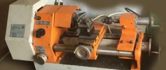
operating
principle of a screw
-
cutting lathe
is that the workpiece is clamped in a horizontal position by the jaws of a chuck mounted in the front “headstock”
of the machine
. A cutter fixed in a tool holder is brought to the rotating workpiece.
Assessment of professional risks in an organization
Occupational safety management system at the enterprise