Scope of application
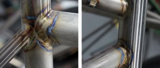
The high pressure welding machine is used as a current source to ignite and maintain the arc for the process of welding, surfacing and gouging of steel. It is used when laying pipelines and steel structures:
- low carbon;
- structural;
- corrosion resistant.
The bath is protected by hydrocarbon . On units of the VD-306 series, welding is performed with electrodes of various brands, including non-consumable ones under argon.
Related Posts via Categories
- Resanta SAI 160 – for welding in domestic conditions
- Resanta SAI 250PROF – inverter for professional welding
- Semi-automatic welding machine of inverter type - welding without difficulty
- Do-it-yourself welding machine – is this possible?
- How to weld with a welding inverter - it’s really simple!
- Forsazh 161 – Russian inverter for high-quality electric arc welding
- EWM PICO 162 – true German quality
- How to choose a welding inverter - selecting equipment for welding
- Blueweld Prestige 164 – reliable and easy-to-use welding inverter
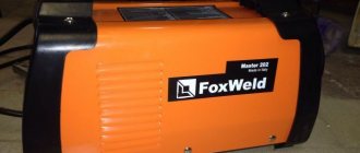
- Foxweld Master 202 – high-quality MMA welding without problems
Specifications
The unit is designed for welding in MMA and TIG modes. The welding transformer VD 306 has the following technical characteristics and positive qualities:
- works from 3 phase current and generator;
- smooth adjustment of settings;
- operation in the temperature range from – 40⁰ to + 60⁰;
- not sensitive to voltage surges and decreases;
- the level of stabilization is high;
- easy ignition.
Most models in this series have an operating mode of 60%. They work equally well at equipped posts and in field conditions far from power lines.
Appendix 3
Cleaning welds from slag should be done only after the seam has completely cooled, and always while wearing glasses with plain lenses. The windings are made of aluminum winding wire of the APSD brand.
The external characteristics are shown in Figures 5, 6 and 7. In manual arc welding mode, the voltage at the working clamps is 40 V. A stable arc, high-quality seam and reliable design make this device an ideal machine for any enterprise.
The current adjustment range depends on external characteristics.
A rectifier control unit is installed in the upper right part of the front wall. Claims about inconsistency of the used configuration with the diagrams and lists of the passport by the manufacturer will not be accepted. Precious materials specified in GOST 2.
Read more: Estimate for installation of electrical equipment sample
The electrical circuit diagram is shown in Fig. When operating the rectifier on a PC, the mode is selected by test welding. When welding on a PC with straight polarity, connect the cable connected to the electrode to the “—” connector. All repair and maintenance work should only be carried out after disconnecting from the mains.
Ground one of the output terminals of the rectifier depending on the welding polarity. To do this, you need to: - make a bracket according to the drawing given in Appendix 5; — make 3 pieces of cable with a cross-section of at least 10 mm2; — dismantle the cover covering the window for installing the circuit breaker; — install the switch in the window and secure it with a bracket; — connect the cables to contacts 1, 3 and 5 of the starter pos. In manual arc welding mode, the voltage at the work clamps is 40 V. Operation without a protective casing is prohibited. The appearance of the external characteristics is shown in Figures 5,6 and 7.
File information
If ventilation is disrupted, the KM2 starter, in the circuit of which there are KVZ relay contacts, disconnects transformer T1 from the network. To do this, you need to: - make a bracket according to the drawing given in Appendix 5; — make 3 pieces of cable with a cross-section of at least 10 mm2; — dismantle the cover covering the window for installing the circuit breaker; — install the switch in the window and secure it with a bracket; — connect the cables to contacts 1, 3 and 5 of the starter pos. The electrical circuit diagram is as follows: By its design, the VDU welding machine is a step-down transformer with a semiconductor block that rectifies the incoming current. When servicing and operating the rectifier, it is necessary to comply with the requirements of regulatory documents on occupational safety in force in the region where welding work is performed.
Each rectifier is designed for only one of those indicated in the table. Precious materials specified in GOST 2. The power rectifier unit consists of six thyristors VS1-VS6 7 type T-T, assembled according to a six-phase rectification circuit with an equalizing reactor. When the rectifier is properly cooled, air should be drawn in from the valve side. VDU 506 in real factory conditions - repair (spontaneous shutdown).
Design features and operating principle
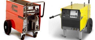
The rectifier VD-360 is relatively small in weight and dimensions. For ease of movement, many models have wheels. Built-in grounding. A three-phase step-down transformer provides a falling external characteristic .
Unstable voltage does not affect the output current. The rectifier consists of units and parts:
- frame;
- control Panel;
- winding;
- rectifier;
- stabilizer;
- circuit breakers;
- fan.
The cooling system is forced, the fan turns on automatically along with the equipment. On the body of the device there are:
- push-button switch;
- control panel with digital display and adjustment knobs;
- ammeter;
- network connector;
- welding cable connectors;
- warning lamp;
- ground bolt.
Rotating handles allow you to smoothly adjust the current strength and other parameters. In case of overheating, the rectifier automatically switches off.
Contents of delivery
The VD series welding rectifier is supplied complete with:
- current converter;
- passport;
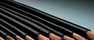
- power cable.
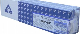
The new device is packaged in cardboard boxes. They indicate the model and technical characteristics of the rectifier. Additionally, holders for coated and non-consumable electrodes may be included .
Varieties
Welders of the VD-306 series are presented in modifications: ST, B, Sh, M1 and special versions for a specific climate, for example UZ.
Comparative characteristics of the welding machine VD 306 in various design changes.
| Options | VD-306B | VD-306M UZ | VD-306 UZ |
| Dimensions, mm | 690×360×640 | 1 040×360×315 | 660×565×510 |
| Weight, kg | 87 | 65 | 104 |
| Rated current, A | 300 | 315 | 315 |
| Operating mode, % | 25 | 55 | 65 |
| Current regulation limits, A | from 25 | from 30 | from 30 |
| No-load current, A | 70 | 75 | 80 |
All rectifiers listed in the table have the same indicators:
- 3 phases;
- industrial voltage 380 V;
- working – 32 V;
- smooth adjustment.
The digital display and stepless control allow you to precisely adjust the equipment to the required mode.
Unacceptable operating conditions
Considering the design of the device, the welding transformer VD 306 is prohibited from operating in rooms where the atmosphere contains:
- dust;
- vapors of caustic substances;
- fire hazardous atmosphere;
- substances that destroy insulating materials.
Important! Working in conditions harmful to the machine leads to the destruction of the equipment and endangers the health of the welder.
For modifications
Model VD-306 is a mobile all-body welding machine and consists of:
- transformer;
- rectifier;
- magnetic shunt;
- emergency shutdown system;
- fan;
- casing
The VD-306 rectifier feeds the electric arc and operates with a direct current output. Performs surfacing and welding . Connects to industrial current 380V.
Operating parameters of VD-306:
- current 315 A;
- mode 60%;
- voltage from 32 V;
- welding current limits 30 – 315 A;
- the adjustment is smooth.
The rectifier is packaged together with a 3 m cable and a passport in the usual version and with ultrasonic climate protection. Protection degree IP22 . The ground clamp is located on the base of the chassis.
The presence of a welding choke in the design of the rectifier makes it possible to weld high-alloy steels with a non-consumable electrode in an argon environment with or without the use of filler wire.
Setting modes and circuit
Opening and closing the magnetic shunt changes the inductive leakage. The shift is made by rotating the handle on the top of the body. The current value required for operation is set depending on the electrodes used and the type of metal being welded.
Current is supplied to the primary winding, then the inductor forms a saturated electromagnetic field. It creates an excitation current, which stabilizes and passes through the rectifier to the holder, forming an arc.
Another rectification circuit is also used, using diodes or thyristors in continuously variable welding machines
VDU-306MT “Track”
The welding rectifier with universal characteristics VDU-306MT is intended for use as a direct current power source for one welding station when:
- manual arc welding, cutting and surfacing of metals (MMA) with coated piece electrodes;
- mechanized welding with a consumable electrode in an environment of protective inert or active gases (MIG/MAG) gases, or using self-shielding flux-cored wire when the unit is equipped with an appropriate semi-automatic device;
- manual welding with a consumable electrode in an inert gas environment (TIG).
Design "Track" - on a platform with shock absorbers of increased vibration resistance - for work in harsh climatic conditions as part of mobile welding units.
The VDU-306MT rectifier is the latest development and differs significantly from all known rectifiers of the VDU series in its welding properties. The use of reliable power thyristors controlled by a microcontroller ensures the formation of external characteristics for various types of welding.
When performing manual arc welding with a coated electrode, VDU-306MT provides:
combined external current-voltage characteristic; smooth regulation of welding current in the range from 30 to 315A without intermediate switching; remote control of welding current at a distance of up to 30m; selection and installation of the slope of the working area of the external characteristic. This makes it possible to obtain both high current stability and the ability to quickly change it when manipulating the arc length, for example, to hold the pool when welding in vertical and ceiling positions; “hot start” mode - an adjustable increase in current when igniting the arc, which ensures almost perfect ignition, as well as high quality of the initial section of the seam; short circuit current boost mode
Depending on the type of electrode coating and the spatial position of the weld, on the one hand, low spattering is ensured, and on the other, energetic droplet transfer without sticking of the electrode to the pool, which is especially important when welding vertical and ceiling seams; anti-stick protection function, which limits the long-term short circuit current, thereby reducing the adhesion strength of the electrode to the part, preventing peeling of the electrode coating and facilitating re-ignition; limiting the open circuit voltage to a safe value of 12V;
Mechanized welding ensures:
- smooth, including remote, welding voltage adjustment;
- optimization of dynamic parameters when welding with short circuits, reducing spatter;
- the ability to connect and work with various types of feed mechanisms, including those intended for welding in installation conditions with self-shielding flux-cored wire.
Certified by AC Gazprom, included in:
|
| Certified by JSC VNIIST, included in: RD 08.00-60.30.00-KTN-050-1-05 “Welding during construction and major repairs of main oil pipelines.” |
For any welding method, operating parameters are specified digitally in absolute values. The current and voltage values characterizing the welding mode are displayed on digital indicators. Storage in memory and reproduction of preset modes, including those selected by the welder, are provided.
Operating temperature from -40 to +400С.
| Specifications: | MMA | MIG/MAG | TIG |
| Rated welding current, A (at PN-100%) | 315 | ||
| Rated arc voltage, V | 32 | 29 | 22 |
| Welding current control limits, A | 30 — 350 | 50 — 350 | 30 — 350 |
| Operating voltage regulation limits, V | 21 — 34 | 15 — 32 | 11 — 24 |
| Slope coefficient of external characteristics, V/A | 0,4 — 2,0 | ∞ | |
| Open circuit voltage, V | 12 | 85 | |
| Rated supply voltage, V | 380 | ||
| Rated frequency, Hz | 50 | ||
| Number of power supply phases | 3 | ||
| Power consumption, kVA | 23 | ||
| Overall dimensions, mm | 710 x 670 x 750 | ||
| Weight, kg | 182 |
The lineup
Marking VD-306 means arc rectifier, 30 A rated current, model version 6. The unit has been operating for several decades in various conditions where other welding machines cannot withstand and quickly break down. Therefore, modernized devices have been created on its basis. The VD-306 series has many modifications . The most popular models among welders:
- VD-306D for large-scale production and work in field conditions;
- rectifier VD-306Sh operates from a network of 380 W and consumer 220 W;
- the improved VD-306M1 allows you to cook additionally with alternating turns;
- VD-306I is an upgraded modern inverter device based on a rectifier.
In addition, there are models made in various climatic versions for work in northern and tropical conditions.
DIY welding rectifier
A rectifier for a welding machine is built around semiconductor elements, the essence of which is to pass electrical currents in only one direction. Today, three devices can be used in rectification circuits:
- diode (the best because it is the simplest; when using it, there is no need to introduce control units into the rectifier circuit);
- thyristor (for current to flow, it must receive a signal from the control system; when the passing current drops to zero or the voltage across it becomes less than in the next phase, the valve closes);
- transistor (a fully controllable “valve”, to open and close which you need to send a signal to the control electrode, and also the most expensive element).
It is best to use a diode, you might think, it is simpler and more convenient to use. However, there is one feature: when using diodes, the electrical circuit will require the introduction of a resistor to regulate the current. When using a transistor or thyristor, voltage regulation can be carried out by the control unit, through a delay in the opening and closing of the “valves,” reducing the voltage at the output of the rectifier and thereby reducing the current.
It is very important to choose any of the above elements with a margin. The actual current flowing through the circuit should be 1.5-2 times less than the rated current for which the semiconductor is designed. The maximum reverse voltage of the “valve” should be 2 times higher than the voltage on the secondary winding of the transformer
Otherwise, breakdowns of elements or failure due to overheating are possible.
The maximum reverse voltage of the “valve” should be 2 times higher than the voltage on the secondary winding of the transformer. Otherwise, breakdowns of elements or failure due to overheating are possible.
Using a diode bridge involves the use of a powerful resistance to regulate the welding current. The ideal option is to use a ready-made rheostat in the form of nichrome or nickel wire wound on a heat-resistant dielectric. You can choose a fechral acceleration stage for electric motors, or, as a last resort, steel wire, again wound on a dielectric. When choosing a resistance, you should assume that a fully introduced resistance into the circuit will reduce the current to zero. The length of the rheostat is calculated using the following formula:
- L=R/r*S;
- where R is the total resistance value required to reduce the welding current to zero;
- r is the resistivity of the material, taken from the reference book, optionally Wikipedia;
- S – section of the wound wire.
Another element that is sometimes used in a rectifier circuit is a choke. Calculating its parameters is quite difficult and time-consuming; determining a simple inductance value will not help. Even if you know the number of turns, the density of copper winding on the magnetic circuit, as well as the presence of a gap between the wire and the steel core, can have a significant impact on the inductance.
The way out of this situation is an experimental determination: we wind the choke in several layers with five or six taps, perform test welding and select the inductance based on the characteristic crackling sound, as well as splashes of molten metal. The less splashing and less crackling, the better. However, the introduction of inductance is not always required, since the inductance of the transformer windings may be sufficient to ensure the falling Volt-Amp characteristics of the welding machine.
Preparing the device: rules of use
Before starting work, you should inspect the integrity of the housing, insulation of cables and hoses. Check all contacts, terminals, clamps. After this, you should connect the case grounding and turn on the device.
Before starting work, you should set the settings and make a test seam. after that you can start working.
Welder of the 5th category of the central steelworks plant of Large-sized metal structures Bogdanov S.D.: “Dust settles on the windings and microcircuits of the equipment and leads to overheating and disruption of operation. If there is a compressor on site, the rectifier should be blown with a stream of compressed air through the air intake slots before operation. If work is carried out outdoors with normal dustiness, cleaning should be done once a week. Welding in an industrial enterprise with a large number of stations requires daily maintenance of the device. After this, you can begin checking connections and terminals. If there is no compressor, the dust is removed with a soft brush.”
general information
AC or DC - which is better? In the 21st century, this question haunts many welders. Previously, the welding machine would work intermittently in any case, and the master actually had no choice. But with the advent of rectifiers and inverters on the market, the choice has increased hundreds of times. And now it’s no longer easy to figure out which device to choose.
We decided to help you and tell you about the features of both alternating and direct current.
Let's start with a break. Alternating current is the basis. This is what we get from the outlet when we connect a welding machine or any other electrical appliance. Welders of the old format (transformers) worked on alternating current. Such a device made it possible to obtain a welding current of several hundred Amperes from 220 Volts. Which is more than enough for manual arc welding.
But times have changed. Technological progress did not stand still, and over time, devices appeared that learned to convert alternating current coming from the network into direct current. Such devices include a rectifier and an inverter. Please note that when they say AC welding inverter, they mean that this device uses alternating current for power, but converts it to direct current.
What does all this mean in practice?
When DC machines went on sale, welders had a unique opportunity to compare them with traditional alternating machines. And they were surprised. Compared to modern inverters and rectifiers, transformers were much more difficult to use.
It's all about the AC characteristics. Because of them, the arc is ignited reluctantly and burns unstable. As a result, the seams are less even and durable. This is especially noticeable when the work is performed by a less experienced craftsman.
It also turned out that AC machines generate more noise, which affects the welder’s performance. In addition, a classic transformer consumes more welding electrodes, and metal is constantly splashed during work.
At this point, you probably thought: “Well, why then do we need AC devices if they have so many disadvantages?” In fact, it's not that simple. It’s not for nothing that the question “Which is better: direct or alternating current?” raises so many questions and discussions.
Alternating devices (transformers) are indispensable when you need an inexpensive, but at the same time powerful and reliable welder. Also, alternating current welding has proven itself to be excellent when welding metals with an oxide film on the surface. These are, first of all, aluminum and stainless steel. Transformers also cope well with welding contaminated parts, if there is no way to clean and grind them.
Also, AC machines can easily handle welding in the field, are unpretentious to storage and operation, and can weld even the thickest metal due to their large power reserve.
A few words about the welding arc
We mentioned above that when welding with alternating current, the arc burns unstable. This is true, and this problem requires special attention if you are a novice welder. When we talk about instability, we mean that the arc seems to “walk” when forming a seam. It deviates from the axis, and sometimes this is even noticeable to the naked eye.
Also, it is sometimes difficult for beginners to ignite an arc, since the alternating current apparatus does practically nothing to facilitate this. Beginners often strike the arc incorrectly, and it may go out during welding due to too much vibration.
These features discourage many newbies from purchasing a transformer because they are concerned about the quality of the work. But we believe that a transformer is, on the contrary, an excellent simulator for honing your welding skills. If you learn how to cook with a transformer, you can use any other device without any difficulties. In addition, the transformer is an excellent basis for rework and modification. It can be easily converted into a DC apparatus if you have knowledge of electrical engineering.
Work safety
The safety requirements state:
- The place for welding must be equipped with a fire shield;
- you cannot turn on the equipment without grounding;
- if the cable is damaged, it should be replaced;
- all contacts must be tightened;
- the part is placed on a special rack or plate and secured.
The welder must work in a special suit made of non-flammable material, leather boots, gloves and a mask. To preserve the equipment, it is imperative to maintain the operating mode and allow the device to cool.
General information
This device is characterized by a variety of work performed. Depending on the type of design, the rectifier can be used in the following types of welding work:
- Electric arc welding. Coated electrodes are used as filler material.
- Work in a protective gas environment. In this case, the equipment is equipped with a feeding mechanism of the PDGO-510 type.
- Submerged arc welding. For operation in semi-automatic mode. In these works, the filler material is flux-cored wire.
- Work as a manipulator. Some models are equipped with a rectifier as a current source.
Manufacturing companies
In the Russian Federation, several enterprises produce VD-306 rectifiers. Among them:
- LLC "RVS-Techno M" - Moscow;
- LLC "TDAvtomatika" Smolensk;
- JSC NTS St. Petersburg.
In specialized stores you can purchase products from other manufacturers. Rectifiers differ in the design of the housing and some characteristics .
For a long time, VD-306 rectifiers have proven that a simple device can guarantee high-quality welding. The equipment operates reliably in different conditions.
terms of Use
According to the instructions, operation of the welding rectifier is possible only if the following conditions are met:
- The work is carried out in enclosed spaces with a functioning ventilation system. Work outdoors is permitted only in normal weather conditions.
- The level of dust in the working area should not exceed the maximum permissible concentration adopted for industrial premises.
- The temperature range is from -10 to +40 Cº.
- The working area is located at an altitude of up to 1000 meters above sea level.
- The humidity level of the production area should not exceed 80%.
During operation, the device should not be subjected to external mechanical influences.