Measuring and marking workpieces using a height gauge
Let's talk about how workpieces are measured and marked when using a manual gage.
Measurements
Take measurements with a manual gage in this order.
- Place the foot holder onto the protrusion of the appliance frame.
- Install the leg into the groove of the holder. Secure it with the locking screw.
- Place the gage gauge on the reference reference plate.
- Make sure that the device is level.
- Holding the base of the tool with your left hand, move the frame up and fix the leg above the workpiece.
- Place the product under the height gauge leg.
- Lower the frame until the leg makes firm contact with the top surface of the workpiece.
- Secure the position of the frame with another locking screw.
- Take the readings.
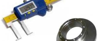
Photo No. 2: measuring the height of the product using a height gauge
Marking
Most often, using gage gauges, lines parallel to the horizontal reference plate are applied to the workpiece. For this:
- set the frame to the desired height (you can evaluate the correctness by the values on the scales of the device);
- fix the frame with the locking screw;
- install a scriber with a carbide tip into the groove of the holder;
- securely fasten it using the locking screw;
- Place the marking gauge and the workpiece on the measuring plate (the scriber should touch the workpiece with force);
- To obtain a horizontal line, move the device along the stove, holding the base.
As a result, a clearly visible line will appear on the surface of the workpiece at the desired height.
Photo No. 3: marking the workpiece with a height gauge
Tool checking
The technique for checking the height gauge provides the following. First, you should check the setting zero of the tool used. To do this, the device is placed on a reference plate and moved in the longitudinal direction. The control line should not have broken sections or other deviations that, in absolute terms, exceed the limits of accuracy. The digital height gauge is checked in the same way, only the indicators of the digital display are controlled.
The purpose of the gage gauge - accurate drawing of dimension lines and taking measurements - can be fully realized if the following rules and requirements are observed:
- Significant fluctuations in temperature and humidity during operation are unacceptable. In particular, the normalized temperature range is 20±10 °C, and the relative humidity is 70±5%.
- If the diameter or configuration of the measuring head changes, the verification must be performed again.
- Verification is always carried out several times (at least three), after which the vernier gage readings are compared with each other. The digital type instrument is verified by the deviation of the readings of the included display screen.
To check the results obtained, a reference micrometer is used, the accuracy of which must be no lower than the accuracy of the equipment being verified.
How it works and works
GOST 164-90 provides for the following standard gage device:
- base;
- yardstick;
- vernier (scale for counting additional readings in fractions of mm);
- frame with micrometric feed;
- holder for fastening replaceable tips;
- reading prism (or scriber, depending on the actions with the tool).
Device and main parts
In accordance with the methodology prescribed in GOST 164-90, the tool should be used in marking mode as follows. All measurements must be carried out on a solid and level slab with minimal surface roughness. A base is installed on this plate, after which, using a frame and a vernier, the required linear dimension is established, which must be reproduced on the surface of the workpiece or semi-finished product. A scriber is placed in the holder, which is rigidly fixed with a micrometer screw. The frame, which is pre-locked with a screw, is pressed together with the body to the surface to be marked. Next, the tool is moved to the required value of the linear dimension, while the tip of the scriber should leave a visible mark on the surface of the workpiece.
The height gauge, whose purpose is measurement, instead of a scriber in the holder, has a prismatic or conical pointer, which ends with a small radius head (according to current standards, this can be 50 or 100 microns).
Reading results
It is not difficult to read the results obtained using a caliper. On the fixed frame (bar), where the main scale is located, determine the integer number (mm). The vernier scale shows hundredths of a millimeter. You need to find a stroke on the vernier scale on the caliper you are using that matches a certain number on the main scale. This indicator will be the value of the part size in millimeters.
Vernier scale
It happens that when measuring, a whole indicator is sufficient. If you want to set the value more accurately, you need to inspect the vernier scale. And on it you need to find the point of coincidence of the two marks. The number on the vernier scale will indicate the tenth value. By adding it to an integer, the user will receive the exact value of the part size.
By hourly indicator
When using a dial caliper, the whole number in millimeters can also be seen on the main scale. As on an analog device, it is determined by the coincidence of marks on both scales. The number presented on the dial shows a value from 0.01 to 0.99 mm, this depends on the value of the scale division. A pointer or dial caliper is a more accurate device than a mechanical (analog) one. It should be used when it is necessary to obtain perfectly accurate data.
By digital display
High-precision (up to hundredths of millimeters) readings of the results obtained when working with a digital caliper are presented on the liquid crystal display of the scoreboard. It is necessary to remember that it has different modes that show measurement results in both millimeters and inches. Such devices are also equipped with a vernier scale. It can be used if, for example, the battery runs out.
Classification
In accordance with the specified standard, the tool in question - height gauge GOST 164-90 - can be classified according to the following parameters:
- According to the method of reading - manual with linear readout, manual with circular readout and automated (digital).
- According to the maximum length of the product being measured (for manual devices), which is indicated in the designation. According to the 1st row of preferred numbers, a manual gage gauge GOST 164-90 type ShR with linear reading can be of the following types: gage gauge ShR-250, gage gauge ShR-400, gage gauge ShR-630 and so on, up to ShR-2500.
- By accuracy class. In particular, according to GOST 164-90, the first class corresponds to an accuracy of 0.05 mm, and the second - 0.10 mm. As the limits of the measuring range increase, the accuracy decreases. For example, if for the ShR-250 type only the upper limit of accuracy is required, then the height gauge ShR-630 GOST 164-90 can have an accuracy of 100 microns. For the least precise instruments, the accuracy is correspondingly reduced to 150 ... 200 microns.
- Along the length of the scale. For instruments of the 1st class it can be 19 and 39 mm, and for the 2nd - 9, 19 and 39 mm.
- The electronic height gauge additionally differs in the display resolution step: 0.03...0.07 mm for the 1st accuracy class and 0.05...0.09 mm for the 2nd accuracy class.
The standard designation of the instrument in question includes all of the above factors. For example, a hand tool with a reading range of 60-630 and a reading accuracy of 0.10 is designated as follows: height gauge ShR-630-0.10 GOST 164-90.
Purpose.
1.1. The height gauge ShR is intended for marking work, drawing marks, transferring dimensions from a scale ruler to a workpiece, and measuring linear dimensions (height). It is used to draw parallel horizontal and vertical lines on parts installed on the slab, as well as to check the correct installation of products. The instrument consists of a frame with a vernier with a hardened measuring surface and a rod with a measuring surface. The frame is equipped with a vernier. The rod is made with a recessed scale, which prevents wear of the scale when moving the rod in the frame. The rod and vernier scales have a matte chrome finish to prevent glare. Used for measurements that do not require high accuracy using the absolute method.
1.2. An example of a symbol for a height gauge with a measurement range of 0-200 mm and a vernier reading value of 0.05 mm:
Shtangenreysmas ShR-200-0.05.
Electronic (digital) height gauges
Today, electronic (digital) height gauges ShRC are most widely used due to their ease of use and greatest accuracy. Let's consider the capabilities of a device of this type using the Mahr height gauge as an example.
The instrument is equipped with an ABS function for switching between relative and absolute measurement methods (to facilitate the use of the first mode, the device has a Reset function to reset the readings and a Preset function to preset values). The maximum measurement speed is 1.5 m/s, the device has a fine-tuning function.
The Reference-Lock/Unlock functions allow you to lock and unlock readings. The data transfer mode is activated by the DATA button. Automatic shutdown of the device after a set waiting time has elapsed significantly saves power on the power supply.
The battery life is close to the life of the device and is about 3 years. Measurement information is displayed on an LCD display, the height of the numbers is 1.2 cm.
The frame of the height gauge and its rod are made of stainless steel, ensuring smooth sliding of the moving surface.
Published 03/28/13.
Completeness
Table 5 — Completeness of measuring instruments
| Name | Quantity |
| height gauge | 1 PC. |
| battery (for height gauges with a digital reading device) | 1 PC. |
| case | 1 PC. |
| passport | 1 copy |
| verification method | 1 copy |
Device
The design of a conventional height gauge is quite simple. Its main parts are:
- massive base;
- a vertical rod on which a millimeter main scale is applied (sometimes it is called a ruler, since in appearance it resembles this particular instrument known from school years);
- main frame;
- vernier (additional micrometer scale on the main frame);
- measuring leg.
All other parts are auxiliary: fastening, adjusting. This:
- screw and nut for moving the main frame;
- micrometric feed frame;
- frame mounting screws;
- holder for replaceable measuring leg tips;
- scriber.
The rod with the main measuring scale is pressed into the base of the instrument strictly at a right angle (perpendicular) to its supporting plane. The rod has a moving frame with a vernier scale and a projection on the side. The protrusion is equipped with a holder with a screw into which a measuring or marking leg is attached, depending on the upcoming operation: measurement or marking.
History of creation
The history of the caliper is quite interesting.
The first such devices were made of wood and were used already at the beginning of the 17th century. But metal calipers appeared in the 18th century with a large scale of divisions. The first real devices with a vernier (an auxiliary scale, which is needed to more accurately determine the number of divisions on the main scale) appeared in London only at the end of the 18th century. Around the middle of the 19th century, calipers began to be produced in industrial quantities and an additional scale was installed on them to increase the accuracy of measurements. Calipers have hardly changed, but they differ from each other in the method and time of manufacture.
Such an ancient measuring device, in which the design has suffered virtually no measurements during all this time, has become the standard of technical excellence and deserves maximum respect to those who invented it. It is unlikely that you will be able to even approximately calculate how many of these tools are currently used by someone.
A type of device that is additionally equipped with a depth gauge is called in professional slang “Columbus”, or affectionately “Columbian”. The name comes from the manufacturer of the measuring instruments, which were supplied en masse under this brand to the former USSR.
Speaking about the aviation industry, such devices were called “Mausers”, and only because they supplied high-quality calipers to the USSR. Let us note the fact that modern calipers are only improved analogues of the very first tool using new technologies.
Interestingly, the vernier was invented by the Portuguese mathematician Pedro Nunes.
At that moment, the mathematician was working to create a navigation device, but the principle that was chosen was based on the fact that the human eye is much more capable of determining the coincidence of divisions on scales than the relative position of one division to two others. This formed the basis of the vernier, which was named after him.
Specifications
Metrological characteristics are indicated in tables 1, 2, 3.
Table 1 - Measuring range, reading value on the vernier, division value of the circular scale of the reading device___
| Modification | Measuring range, mm | Vernier reading value, mm | Dividing value of the circular scale of the reading device, mm |
| ШР 250 | from 0 to 250 | 0,05 | — |
| ShR 400 | from 40 to 400 | ||
| ShR 630 | from 60 to 630 | 0,05; 0,10 | |
| ShR 1000 | from 100 to 1000 | ||
| ШР 1600 | from 600 to 1600 | 0,10 | |
| ShR 2500 | from 1500 to 2500 | ||
| SRK 250 | from 0 to 250 | — | 0,05 |
Table 2 - Distance from the edge of the vernier to the surface of the scale bar of the ShR type gage, the roughness parameter of the measuring surfaces, the deviation of the actual size “g” of the measuring leg from the marked one, the width of the edge of the upper measuring surface of the measuring leg, the width of the arrow of the ShRK gage, the distance between the end of the arrow and the dial height gauges of the ShRK type, deviation from parallelism of the measuring plane of the legs relative to the base of the height gauges_
| Characteristic name | Meaning |
| Distance from the edge of the vernier to the surface of the rod scale of ShR type height gauges, mm, no more | 0,25 |
| The roughness parameter of the measuring surfaces of gage gauges with a reading value on the vernier or scale division value of no more than 0.05 mm according to GOST 2789-73, Ra, µm, no more: - measuring leg - marking leg and base | 0,16 0,32 |
| Roughness parameter of the measuring surfaces of gage gauges at a vernier reading value of 0.1 mm according to GOST 2789-73, Ra, µm, no more than: - measuring and marking legs - grounds | 2 3 m vo o" o" |
| Deviation of the actual size “g” of the measuring leg from the marked one, mm, no more | ±0,02 |
| Width of the edge of the upper measuring surface of the measuring leg, mm, no more: — gage gauges with a measuring range from 0 to 250 mm — gage gauges with other measurement ranges | ,5 ,2 |
| Width of the arrow gauge ShRK, mm | from 0.15 to 0.20 |
| Distance between the end of the pointer and the dial of height gauges type ShRK, mm, no more | 0,7 |
| Deviation from parallelism of the measuring plane of the legs relative to the base of the height gauges, mm, no more than: — gage gauges with a vernier reading value of 0.05 mm and scale divisions of 0.02 mm and 0.05 mm — gage gauges with a vernier reading value of 0.1 mm | 0,010 0,015 |
Table 3 - Limits of permissible absolute error both with loose and tightened frame clamps, at ambient temperature (20±10) °C_
| Measuring length, mm | Limits of permissible absolute error of height gauges, mm | ||
| with the division value of the circular scale of the reading device | with vernier reading value | ||
| 0,05 | 0,05 | 0,10 | |
| from 0 to 400 incl. | ±0,05 | ±0,05 | ±0,05 |
| St. 400 to 630 incl. | — | ±0,10 | |
| St. 630 to 1000 incl. | ±0,10 | ||
| St. 1000 to 1600 inclusive. | — | ±0,15 | |
| St. 1600 to 2500 | ±0,20 |
Table 4 - Main technical characteristics
| Modifi cation | Parallelism tolerance of the upper and lower measuring surfaces of the measuring legs, mm | Tolerance of straightness of measuring surfaces of marking and measuring legs, mm | Overall dimensions (length, width, height), mm, no more | Weight, kg, no more | Average service life, years, not less |
| ШР 250 | 0,006 | 0,004 | 160x70x375 | 1,8 | 5 |
| ShR 400 | 275x120x531 | 5,3 | |||
| ShR 630 | 275x120x761 | 5,7 | |||
| ShR 630 | 0,01 | ||||
| ShR 1000 | 320x155x1169 | 13,0 | |||
| ШР 1600 | 425x200x1770 | 32,0 | |||
| ShR 2500 | 460x200x2670 | 44,0 | |||
| SRK 250 | 0,006 | 160x70x375 | 1,6 |
Table 5 - Operating conditions
| Characteristic name | Meaning |
| Ambient air temperature, °C | from +10 to +40 |
| Relative air humidity at a temperature of 25 °C, %, no more | 80 |
ACCEPTANCE
3.1. To check the compliance of height gauges with the requirements of this standard, state tests, acceptance inspection, periodic tests and reliability tests are carried out.
3.2. State tests - according to GOST 8.383* GOST 8.001* ________________
* PR 50.2.009-94** applies on the territory of the Russian Federation. ** The document is not valid on the territory of the Russian Federation. The procedure for testing standard samples or measuring instruments for the purpose of type approval, the Procedure for approving the type of standard samples or the type of measuring instruments, the Procedure for issuing certificates of approval of the type of standard samples or the type of measuring instruments, establishing and changing the validity period of these certificates and the interval between verifications of measuring instruments are in effect. , Requirements for type approval marks of standard samples or type of measuring instruments and the procedure for their application, approved by Order of the Ministry of Industry and Trade of Russia dated November 30, 2009 N 1081. - Note from the database manufacturer.
3.3. During acceptance inspection, each height gauge is checked for compliance with the requirements of clause 1.5; 2.2-2.7; 2.8.1; 2.8.3; 2.9.3; 2.9.4; 2.11.2; 2.14; 2.15; 2.16; 2.21; 2.22.
3.4. Periodic tests are carried out at least once every 3 years on at least 3 height gauges of each type, from among those that have passed acceptance control, for compliance with all the requirements of this standard, except for paragraphs 2.17-2.20. The test results are considered satisfactory if all tested height gauges meet all tested requirements.
3.5. Confirmation of reliability indicators (clauses 2.17-2.20) is carried out at least once every 3 years according to reliability testing programs developed in accordance with GOST 27.410* and approved in the prescribed manner. It is allowed to combine reliability tests with periodic tests. ________________ * The document is not valid on the territory of the Russian Federation. GOST R 27.403-2009 and GOST 27.301-95 are in force. — Note from the database manufacturer.
What is it needed for?
This type of marking and measuring tools can be used in metalworking and turning workshops to determine the linear geometric dimensions of various parts, the depth of grooves and holes, as well as when marking blanks and parts during assembly and repair work in relevant industries (mechanical engineering, metalworking, automotive industry ). In addition, the height gauge is designed to accurately measure the height of parts placed on the marking area. At the same time, the metrological characteristics of the instrument are subject to periodic verification, the methodology of which is determined by the state standard.
They can make vertical, horizontal and even oblique measurements. True, the latter require an additional unit.
What it is?
First of all, it is worth providing general information about this plumbing tool.
- It also has another name - height gauge.
- It looks similar to a caliper, but is installed to determine dimensions on a horizontal plane in a vertical position.
- The principle of operation of a caliper is no different from the principle of operation of a caliper.
- Its purpose is to measure the height of parts, the depth of holes and the relative position of the surfaces of various body parts. In addition, it is used for marking operations.
- Since the instrument is, in fact, a measuring device, it has a certain verification and measurement methodology.
- The technical conditions of this tool are regulated by GOST 164-90, which is its main standard.
The accuracy of measurements and markings with a height gauge reaches 0.05 mm, even for workers who do not have special skills in working with it.
How to achieve maximum accuracy in operations
Observe the following rules.
- Touch the height gauges only at those points that are specifically designed for this purpose. These include:
pen;
- control reference plate;
- air bearing activating switch;
It is prohibited to touch other elements of the device during the measurement or marking process.
The accuracy of measurements and markings is greatly influenced by the ambient temperature. Due to this:
- carry out operations only at air temperatures from +10 to +20 °C;
- Make sure that the device is not exposed to direct sunlight;
- there should be no drafts in the room for measurements and markings;
- do not install height gauges near heating appliances;
- Do not measure parts that are too hot or cold;
- Before carrying out operations, give the instrument time to adapt if you brought it from somewhere.
Depending on the size of the workpieces, the adaptation period can vary from 15 minutes to 8 hours.
- When two bodies come into contact, vibrations that are invisible to the naked eye occur. Therefore, you need to wait a little before reading the results.
- Don't press too hard. The leg may bend. Even an imperceptible bend will lead to marriage.