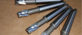
A centering drill is a special metal-cutting tool with a double-sided cutting part and, as a rule, a large diameter shank for clamping into a chuck. The drill has a main thin cutting part, as well as conical cutting edges for countersinking holes for drills of large diameters. Of all types of drills, it is the centering drill GOST 14952-75 that provides maximum quality and accuracy of drilling and strict perpendicularity, eliminating sliding on the surface, which is typical of conventional drills.
TEST METHODS
4.1. Testing of drills should be carried out on drilling, centering and turning machines using auxiliary tools, which must meet the standards of accuracy and rigidity established for them.
4.2. Drills should be tested on samples made of steel grade 45 according to GOST 1050-88 with a hardness of 187 - 207 HB.
(Changed edition, Rev. No.).
4.3. Durability tests are carried out on drills of type B, as well as type A, R or C with diameters of 0.5; 1.6; 2.0; 2.5; 4.0; 10.0 mm at the modes indicated in the table. 8.
4.3.1. Acceptance values of mean time to failure and 95% failure-free operating time should not be less than those indicated in table. 9.
(Changed edition, Rev. No.).
4.4. After performance tests, there should be no chipping on the cutting edges of the drills, and the drills should be suitable for further work.
4.5. A 5% (by weight) solution of emulsol in water with a flow rate of at least 5 l/min is used as a cutting fluid.
Table 8
| Diameter of the drill bit, mm | Feed, mm/rev, for types | Drilling depth, mm, for types | Cutting speed, m/min | Number of holes machined during performance tests | ||
| A, B, C | R | A, C, R | IN | |||
| 0,50 | 0,01 | 0,02 | 1,3 | — | 8 … 10 | 13 |
| 0,63 | 1,5 | — | ||||
| 0,80 | 1,9 | 2,1 | ||||
| 1,00 | 2,3 | 2,6 | ||||
| 1,40 | 0,02 | 2,8 | 3,2 | 25 | ||
| 1,60 | 3,5 | 4,0 | ||||
| 2,00 | 0,04 | 4,4 | 5,0 | |||
| 2,50 | 0,07 | 5,5 | 6,3 | 11 … 13 | 30 | |
| 3,15 | 7,0 | 8,0 | ||||
| 4,00 | 0,08 | 8,9 | 10,1 | 24 | ||
| 5,00 | 0,10 | 11,2 | 12,7 | 14 | ||
| 6,30 | 0,12 | 14,0 | 15,4 | 18 | ||
| 8,00 | 17,9 | 19,5 | 15 | |||
| 10,00 | 22,5 | 24,5 | ||||
Table 9
| Diameter of the drill bit, mm | Acceptance values of operating time for drill type | |||
| A, R, C | IN | |||
| average | 95% | average | 95% | |
| 0,5, 0,63, 0,8, 1,0 | 150 | 45 | 105 | 32 |
| 1,25, 1,6 | 190 | 56 | 140 | 42 |
| 2,0 | 270 | 77 | 170 | 50 |
| 2,5, 3,15 | 290 | 88 | 190 | 56 |
| 4,0, 5,0 | 175 | 53 | 120 | 35 |
| 6,3, 8,0, 10,0 | 150 | 45 | 95 | 28 |
(Changed edition, Rev. No.).
4.6. The hardness of drills is measured according to GOST 9013-59.
4.7. Appearance control is carried out visually.
4.8. The surface roughness parameters of drills should be checked by comparison with roughness samples in accordance with GOST 9378-75 or with standard tools, the values of the surface roughness parameters of which are not more than those specified in clause 2.3.
Comparison is carried out visually using a magnifying glass LP-2 - 4´ according to GOST 25706-83.
4.9. When monitoring drill parameters, control methods and means must be used, the error of which should not be more than:
when measuring linear dimensions - the values specified in GOST 8.051-81;
when measuring angles - 35% of the tolerance value for the angle being tested;
when monitoring the shape and location of surfaces - 25% of the tolerance value for the parameter being tested.
Sec. 4. (Changed edition, Amendment No. 2).
TECHNICAL REQUIREMENTS
2.1. Drills must be made of high-speed steel - in accordance with GOST 19265-73.
2.2. The hardness of the working part of centering drills should be: for drills with a diameter of up to 3.15 mm - 63...65 HRC; for drills with a diameter over 3.15 mm - 63...66 HRC. The hardness of the working part of drills made of high-speed steel with a vanadium content of 3% or more and cobalt of 5% or more should be higher by 1-2 HRC units.
2.3. The roughness parameters of drill surfaces according to GOST 2789-73 should not exceed the values specified in Table 5.
Table 5
µm
| Names of surfaces | Roughness parameters according to GOST 2789-73 | |||
| Version 1 | Version 2 | |||
| The rake surface of the drilling part and the surface of the flutes | — | 6,3 | — | 10,0 |
| Rear surface of drilling and countersinking part | — | 3,2 | — | 6,3 |
| Surface of the clamping cylindrical part | 0,63 | — | 1,25 | — |
2.2, 2.3. (Changed edition, Amendment No. 2).
2.4. Cracks, nicks, rough spots and tarnished colors are not allowed on the surfaces of centering drills (with the exception of grooves, where tarnished colors are allowed at the point where the wheel exits).
2.5. Maximum deviations in the dimensions of combined drills should not exceed: the diameter of the drill part. . . k12; diameter of the clamping cylindrical part. . . h9; cone angles 60° and 75°. . . minus 30′; cone angle 120°. . . ±1°. Note. The dimensions of the nominal diameters of the drilling part should be measured at the beginning of the cutting part. (Changed edition, Amendment No. 3).
2.6. Drills of types A, B and C must have a reduction in diameter on the drilling part towards the shank (reverse taper) within 0.05-0.10 mm per 10 mm of length. (Changed edition, Amendment No. 2).
2.7. The thickening of the core of combination drills towards the shank by 5 mm in length should be:
| for drills up to 3.15 mm diameter | 0.40 mm | ||
| » » St. 3.15 mm | 0.25 mm | ||
2.8. The tolerance for radial runout of the auxiliary edges of the drilling part relative to the axis of the clamping part should be no more than:
| for drills up to 3.15 mm diameter | 0.03 mm | ||
| » » St. 3.15 mm | 0.04 mm | ||
2.9. The axial runout tolerance, checked at the center of the cutting edges, should be no more than:
| for drills up to 6.0 mm diameter | 0.10 mm | ||
| » » St. 6.0 mm to 10.0 mm | 0.13 mm | ||
| » » St. 10.0 mm | 0.15 mm | ||
For drills with a diameter of up to 6 mm, instead of the tolerance of the end runout of the drilling part, it is allowed to check: the difference in half the angle at the tip of the drill, which should not be more than 1°30′; symmetry tolerance in radius expression of the transverse edge relative to the axis of the clamping part of the drill:
| for drills up to 3.15 mm diameter | 0.05 mm | ||
| » » St. 3.15 mm | 0.10 mm | ||
(Changed edition, Amendment No. 2).
2.10. The difference in the widths of the feathers on one drill should be no more than:
| for drills up to 3.15 mm diameter | 0.07 mm | ||
| » » St. 3.15 mm | 0.10 mm | ||
2.11. The values of average time to failure and 95% failure-free operating time of drills made of R6M5 steel, version 2, under the test conditions specified in Section 4, must be no less than those given in Table 6.
Table 6
| Diameter of the drill bit, mm | Operating time (number of holes machined) with drill type | |||
| A, R, C | IN | |||
| average | 95% | average | 95% | |
| 0,5, 0,63, 0,8, 1,0 | 130 | 39 | 90 | 27 |
| 1,25, 1,6 | 160 | 48 | 120 | 36 |
| 2,0 | 220 | 66 | 145 | 43 |
| 2,5, 3,15 | 250 | 75 | 160 | 48 |
| 4,0, 5,0 | 150 | 45 | 100 | 30 |
| 6,3, 8,0, 10,0 | 130 | 39 | 80 | 24 |
Note. For drills of version 1, the correction factor for the average and specified service life is 1.3. (Changed edition, Amendment No. 3).
2.12. The criterion for failure of centering drills with a diameter of up to 3.15 mm is breakage, and from 4 mm and above - wear on the rear surface in accordance with Table 7.
Table 7
mm
| Drill bit diameter | |
| 4,0, 5,0 | 0,4 |
| 6,3, 8,0, 10,0 | 0,5 |
2.11, 2.12. (Introduced additionally, Amendment No. 2).
2.13. On each drill the following must be clearly marked: the diameter of the drill part; manufacturer's trademark; drill designation (last four digits); steel grade. Notes:
1. On drills with a diameter of less than 10 mm, it is allowed not to mark the drill designation.
2. Steel grades R6M5 are allowed; R6AM5 should not be marked.
3. It is allowed to mark the letters HSS instead of the high-speed steel grade; for steel grades containing cobalt, the letters HSS C, while the grade is now indicated only on labels.
2.14. Packaging, marking of transport and consumer containers - in accordance with GOST 18088-83.
2.13, 2.14. (Introduced additionally, Amendment No. 3).
APPENDIX 1 (recommended)
APPENDIX 1 Recommended
The design, dimensions and geometric parameters of the drills are indicated in Figures 1-4 and Tables 1-4.
Damn.1. Type A
Type A
Form 1. Oblique flute drill
For diameters up to 0.8 mm
For diameters St. 0.8 mm
Form 2. Drills with helical flute
Damn.1
Note. The 100° angle and radius are given in a section perpendicular to the slope of the groove.
Table 1
Dimensions in mm
| (0,50) | 5 | 0,10 | 0,03 | 0,10 | — |
| (0,63) | 6 | 0,10 | 0,04 | 0,24 | |
| (0,80) | 7 | 0,15 | 0,05 | ||
| 1,00 | 8 | 0,20 | 0,06 | 0,30 | 15° |
| (1,25) | 9 | 0,25 | 0,07 | ||
| 1,60 | 11 | 0,30 | 0,10 | ||
| 2,00 | 12 | 0,40 | 12° | ||
| 2,50 | 15 | 0,45 | 0,16 | 0,50 | |
| 3,15 | 17 | 0,55 | |||
| 4,00 | 20 | 0,70 | 0,25 | 0,80 | |
| 5,00 | 24 | 0,85 | |||
| 6,30 | 27 | 1,10 | 0,40 | ||
| 8,00 | 34 | 1,40 | 1,00 | ||
| 10,00 | 38 | 1,70 | 0,60 |
Damn.2. Type B
Type B Form 1. Oblique flute drills
Form 2. Drills with helical flute
Damn.2
Note. The 100° angle and radius are given in a section perpendicular to the slope of the groove.
table 2
Dimensions in mm
| (0,80) | 9 | 0,15 | 0,05 | 0,2 | — |
| 1,00 | 10 | 0,20 | 0,06 | 0,3 | 28° |
| (1,25) | 11 | 0,25 | 0,07 | 26° | |
| 1,60 | 13 | 0,30 | 0,10 | 24° | |
| 2,00 | 16 | 0,40 | |||
| 2,50 | 19 | 0,45 | 0,16 | 0,5 | |
| 3,15 | 21 | 0,55 | 21° | ||
| 4,00 | 24 | 0,70 | 0,25 | 0,8 | 19° |
| 5,00 | 27 | 0,85 | |||
| 6,30 | 31 | 1,10 | 0,40 | ||
| 8,00 | 35 | 1,25 | 1,0 | ||
| 10,00 | 39 | 1,40 | 0,60 |
Damn.3. Type C
Type C For diameter =0.8 mm
For diameter St. 0.8 mm
Damn.3
Table 3
mm
| 0,8 | 8 | 0,15 | 0,05 | 0,2 |
| 1,0 | 0,20 | 0,06 | 0,3 | |
| 1,6 | 11 | 0,30 | 0,08 | |
| 2,0 | 14 | 0,40 | 0,10 | |
| 2,5 | 16 | 0,45 | 0,14 | 0,5 |
Marking and metal from which the center drill is made
Centering drills are also marked according to GOST 14952-75. As mentioned above, they have a letter in their designation (A, B, C or R).
A centering drill according to GOST 14952-75 is marked “A” and “B” if it is intended to create a hole at an angle of 60 degrees. The difference here is the presence of a safety cone (letter “B”) or its absence (letter “A”). The marking “C” is used for drills that make holes at an angle of 75 degrees (there is no safety cone), and the letter R is used for drills that make holes with arc-shaped walls.
For example, consider a centering drill with a diameter of 1.0 mm.
If the drill is type “A” and made in the first version, then it will be marked 2317-0101 GOST 14952-75, and if in the second version, then 2317-0001 GOST 14952-75. Here “2317” denotes the specific design characteristics of the drill necessary for its operation, and 0101 is the serial number of the standard size according to factory tables.
Instruments belonging to group “B” are marked differently (in particular, if they are made in the first version, then as “2317-0113”, and if in the second - “2317-00-12”). Type "C" drills are designated as "2317-0124" (in the first version) and as "2317-0022" (in the second version), and group R as "2317-0027". And let us remind you once again that this is all true if the drill diameter is 1 mm.
GOST 14952 75 also assumes that such tools will be made of R6M5 tool steel, its foreign analogue HSS or R9 high-speed steel. However, the steel grade may not be indicated in the marking of centering drills.
Features of different types of drill sharpening
The correctness of the chosen method depends on an accurate assessment of the wear of individual elements. The ones that suffer the most wear are:
- back or front surface;
- jumper;
- set angles;
- chamfered.
Depending on the degree of wear of one of the parameters or several simultaneously, a type of sharpening is selected that can eliminate these shortcomings.
To achieve a high-quality drilling result, it is necessary to correctly select the diameter of the drill and the shape of the cutting edge. To maintain it in working condition and give it the required shape, you should choose the right method (type) of sharpening.
The types used are designated by accepted abbreviations and are divided into the following categories:
- NP - involves consistent grinding of the transverse edge. This allows you to reduce its length, thereby reducing the magnitude of external loads and increasing the period of normal operation of the drill.
- NPL - this type involves processing the transverse edge and ribbon. Which leads to a decrease in the transverse size of the ribbon. This processing helps to obtain the required clearance angle. This reduces the friction force of the cutting edge on the metal surface;
- DP - belongs to the category of double sharpening. Correct application allows you to get one transverse and four additional cutting edges.
- DPL - this processing of metal drills involves sequential sharpening of the ribbon. As a result, better conditions are created for heat removal, reliability and durability are increased.
All types of processing are aimed at creating optimal conditions during drilling. Descriptions of the rules and characteristics of sharpening are established by the relevant standards. All parameters for sharpening a drill for metal are summarized in a single table. It shows the geometry of the cutting edge shapes used for various cutting conditions. The listed types of sharpening allow for high-quality restoration of the parameters of the cutting part of a tool with a diameter of up to 100 mm.
When applying the listed methods, it is very important to take into account the parameters of the metal from which the tool is made. This is necessary for the correct selection of a sharpening tool (grinding wheel)
For example, for high-quality restoration of drills made of high-speed steel, experts advise using an electrocorundum grinding wheel. If the drill is made of carbide materials, it is advisable to process it with a diamond-coated wheel. The operation of restoring parameters leads to significant heating of the part, especially its cutting edge. Therefore, this process must be carried out in stages using coolant.
Particular attention should be paid to restoring the basic parameters of the drill in a home workshop. It is necessary to ensure high quality of the following indicators:
- the same length of edges and ribbon (measurement can be made with an existing measuring tool);
- sharpness of both edges (check is carried out visually);
- values of both angles (front and back).
To simplify the latter task, many craftsmen make their own templates that provide the required sharpening angle. Exact observance of these parameters and correct pointing of the jumper significantly increases the service life of the drill.
However, there are certain types of drills, the specifics of which significantly complicate the sharpening process. Problems with sharpening a twist or step drill are associated with the complex geometry of their design. Therefore, sharpening of such tools is carried out on special machines using developed equipment.
Sharpening step drills for metal is particularly difficult. Such sharpening can only be carried out using special tools and extensive experience. However, it should be noted that the majority of such tools cannot be re-sharpened at all.
Neither method is applicable to diamond-coated drills or other hard bits.
We choose metal drills depending on their type and purpose
When choosing a drill for metal, the master, first of all, looks at its appearance.
Twist drills
The most popular type. These simple, cheap drills are designed to make blind and through holes of certain diameters. The working part is a cylindrical rod with two cutting edges. The grooves serve to remove chips.
Photo No. 1: twist drills for metal
Cone drills
The working parts are shaped like cones. In everyday life, such metal drills are rarely used. They are best suited for special machines and two-handed drills. They are used to make holes with diameters from 6 to 60 mm.
Photo No. 2: cone drill for metal
How to choose a step drill for metal
Tapered metal step drills are best suited for making holes in thin sheets. These tools look like this.
Photo No. 3: step drill for metal
As you can see, when making holes of different diameters in thin sheet metal, the tool does not need to be changed.
Center drills for metal
Centering drills for metal are designed for making centering holes in workpieces. They are necessary for fixing products on various special machines.
Photo No. 4: centering drills for metal
Left hand drills
Left hand metal drill bits are specifically designed for drilling out bolts and screws with broken heads. This cannot be done using ordinary drills. The bolt or screw will turn.
Photo No. 5: left-handed metal drill
Core drills for metal
Core drills or annular cutters are used to quickly drill large diameter holes (from 15 to 100 mm) in metal workpieces. The operating principle of such tools is based on core milling. It uses 4–12 times less energy than using conventional drills.
Photo No. 6: core drills for metal
These drills are designed for installation on drilling, milling and turning machines. For manual work, use special tools with QuickIN Plus type clamps.
Feather prefabricated drills
Spade drills are excellent for machining cast iron, structural steel and hard forgings. These tools are used to make shaped and stepped holes of large diameters. Feather prefabricated drills consist of holders to which pentagonal cutting inserts of various sizes are attached. They have special grooves to remove chips.
Photo No. 7: prefabricated feather drills with plates
Carbide drills
Carbide drills are made using particularly durable materials. There are the following types of such instruments.
- Monolithic.
- Welded.
- With special plates.
Photo No. 8: carbide drills with inserts
Such tools are purchased for processing workpieces made of heat-resistant steels and titanium alloys. Next, we’ll tell you how to choose a high-quality twist drill for metal.
Tips for choosing
The choice of center drill will depend on the size of the hole to be made
The weight of the workpiece, which is fixed in the metalworking machine, is also taken into account. Standard sizes depending on the weight of the workpiece are regulated by GOST - the greater the mass of the part, the larger the drill diameter required
Each drill diameter has 2 design options, so its type is selected depending on the requirements for the roughness of the hole walls.
The combined centering drill is selected according to the requirements for the type of holes specified in the design drawings. To determine the quality of a tool, there are a number of items by which it must be checked.
Compliance with Rockwell hardness standards. The centering drill data is indicated in its technical specifications. A high-quality tool has an indicator of at least 63-66 HRC. Exceeding these standards leads to the fact that the drill will be fragile and short-lived. Low standards will cause the tool to become dull very quickly.
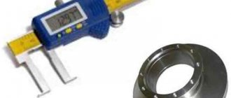
The drill corresponds to the declared diameter. You can check this with a micrometer. The elongated working blade of the drill is subject to measurement - and if its diameter exceeds the permissible error standards, it will not be possible to obtain a hole of a given size using this tool.
Determine the integrity of the product
This is especially important for its cutting part, as well as for the cone-shaped crown. There should be no cracks or gouges on the tool where the working surfaces are.
During operation, the drilling tool gradually changes the angle of the cutting inserts. This leads to a decrease in cutting speed and excessive heating of the drill. Over time, any drill requires sharpening, which must be done while maintaining the angle of inclination of the cutting part.
Recommendations for choosing a center drill
There are no universal centering drills. A centering drill must be selected based on a number of factors.
Let's list them:
- Firstly, you need to take into account the material with which you will be working, as well as the diameter and length of the working part, drill material, taper and type of centering hole.
- Secondly, if you plan to center the part before drilling it, the centering drill should be selected smaller in diameter than the size of the hole after final drilling. And vice versa, if you need to drill out a tightly stuck screw that cannot be removed with a screwdriver, then the drill must be selected with a diameter similar (or larger) to the screw that needs to be drilled.
- Many people use center drills to drill holes for threads. In this case, you need to select the diameter of the drill so that it is smaller than the diameter of the thread. Otherwise, it simply won’t be possible to cut it.
- It is also necessary to take into account the requirements for the roughness of the hole walls, since centering drills are available in two types.
Drill selection parameters according to GOST
Having looked at the GOST for a self-centering drill, it becomes obvious that you need to pay attention to a number of characteristics, such as:
- Appearance. It's simple: the instrument should never have scratches, dents or any externally noticeable mechanical defects.
- Accuracy. We look carefully at this indicator, because it determines what the tolerances for deviations in the diameter of the drilled holes will be. For example, if the diameter of the working area of the centering drill is less than 8 millimeters, then the deviation should not be higher than 0.05 millimeters.
- Hardness. If this parameter is deviated, the drill will not last long. If it is low, then the drill will not be resistant enough during operation, and if it is too high, then the drill will be fragile. The hardness should be between 63 and 66 HRC, according to the Rockwell hardness scale.
- Length. This parameter is responsible for the performance of the drill. It must be selected based on the length of the workpiece.
Tricks at work
If it was not possible to remove the pin fragment with an extractor, then it was removed using a tap. To do this, I drilled out the hole drilled along the axis of the stud a little more and restored the thread with a tap. If the diameter of the hole drilled along the axis of the stud was chosen correctly, then when the tap passes, the remnants of the threaded part of the old stud are chipped and removed. The main thing is to correctly calculate the diameter of the hole. This is easy to do if you know the diameter and pitch of the thread. So, for example, for a thread M8×1.5 mm, you need to subtract the pitch value from the diameter of the thread (8 - 1.5 = 6.5 mm) and reduce it by another 0.5...0 .6 mm. That is, the drill should have a diameter of approximately 6 mm so that when drilling it does not affect the ridges and valleys of the thread on the stud piece and leaves a minimum of metal that the tap can easily crumble and remove. We could go on and on about various examples of “inappropriate” use of a center drill – there are many of them. My advice to home craftsmen: get this useful tool in your workshop and you won’t regret it. It is not so difficult to purchase such drills in specialized tool stores and on the market; they are on sale quite often.