Cutting modes in machining are a set of operating parameters that determine the speed, force and depth to which the cutter is immersed into the part during the process of removing a layer of metal from its surface.
Their basic values are determined by calculation based on the geometry of the cutting edge of the tool and the workpiece, as well as the speed of their approach. Real metal processing processes are influenced by many factors related to the characteristics of the tool used, machine equipment and the material being processed.
Therefore, empirical formulas are used to calculate technological cutting conditions. And the basic values are included in their composition along with such reference values as groups of correction factors, durability values, parameters of processing conditions, etc.
Cutting modes affect not only the specified accuracy and processing class of the product. They determine the force with which the tool edge acts on the metal, which directly affects power consumption, the level of heat generation and the wear rate of the tool.
Therefore, the calculation of their parameters is one of the main tasks of technological services of enterprises. Despite the many varieties of metal-cutting equipment and tools, all machining is based on common principles.
Therefore, methods for calculating cutting modes are unified and systematized into three main groups: for turning, for drilling and for milling. All other types of calculations are derivative.
Parameters for calculating cutting conditions
The main calculation of machining modes is based on three parameters: cutting speed (V), feed (S) and depth of cut (t). To obtain practical values of these parameters that can be used in production, at the first stage their calculated values are determined.
Then, using empirical formulas, lookup tables and data from equipment data sheets, they are used to select technological cutting modes that will best suit the type of material being processed, the capabilities of the machine, as well as the type and characteristics of the tool.
Not only the quality of processing, but also indicators such as productivity, production costs and operating costs depend on the correct calculation and selection of these parameters. In addition, the force exerted on the tool during processing affects not only the rate of its wear, but also the condition of the equipment and fixtures.
The consequence of working at too high speeds and feeds is unacceptable vibration and increased load on the components and mechanisms of the equipment. And this can lead not only to loss of accuracy, but also to machine failure.
As a rule, cutting conditions are checked and adjusted during trial processing of the part. Therefore, their choice depends not only on the correctness of the calculations, but also on the experience of the technologist and machine operator.
Speed
The time cycle for processing a part consists of three basic components: preparatory-final, auxiliary and main time.
The latter includes all metal cutting operations at specified conditions. Due to the nature of machining, prime time is the most expensive component of the part processing cycle. Moreover, its value, and therefore the cost of the product, directly depends on the cutting speed. Therefore, the correct selection of this parameter is important not only from a technological, but also from an economic point of view.
In general, the formula for the calculated cutting speed looks like this:
In this formula, the value of parameter D depends on the type of processing. For turning, this is the diameter of the part; for other types, this is the diameter of the cutting tool (drill, cutter). Parameter n is the spindle rotation speed in revolutions per minute.
In this way, the theoretical value of the cutting speed is determined, which is the starting point for subsequent calculations. In particular, it is used to calculate the theoretical depth of cut, which is denoted by t. Due to the fact that the actual cutting speed depends on many factors, it is calculated using an empirical formula in which the only calculated value is t:
Here Cv is a dimensionless constant depending on various aspects of processing; T is the standard tool life time; t—cutting depth; So—feed; Kv is a summary coefficient, which is the product of eight correction factors.
Innings
Feed (denoted S) is the path that the cutting edge travels per unit. Depending on the type of machining, the feed may have different dimensions. The length of the traveled path is always measured in millimeters, but it can be correlated with either one revolution (in turning) or one minute (in drilling and milling).
Thus, during drilling, this is the amount of movement of the tip of the drill deep into the surface in one minute (mm/min), and during turning operations, the longitudinal or transverse movement of the cutter per revolution of the part (mm/rev).
Due to the specific nature of individual finishing operations, a parameter such as “feed per tooth” is used for them, which is measured in mm/tooth. It is used when working with a tool that has several blades, and its value shows which path the edge (tooth) of one blade has traveled in one revolution of the spindle.
The value of this parameter can also be calculated by dividing the tool feed per revolution by the number of cutting blades.
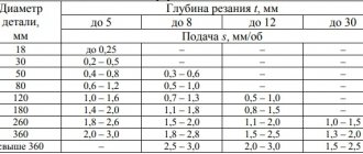
Since the feed directly depends on the passport parameters of a particular equipment, its value, as a rule, is not calculated, but is selected from tables in the relevant technological reference books.
The productivity of metal-cutting equipment directly depends on the feed rate. In addition, it is the basic parameter for calculating the main processing time. Theoretically, during machining it is necessary to set the maximum possible feed value.
But in this case, restrictions on the capabilities of machine equipment and requirements for the cleanliness class come into force.
The maximum feed values are used for roughing and roughing, and the minimum feed values are used for finishing operations.
Depth
The depth of cut is the thickness of the metal removed per unit stroke of the cutting edge.
Its value depends on the design of the cutting part of the tool and its strength parameters (including the maximum tangential force), as well as the power of the machine, the hardness of the material being processed and the requirements for surface cleanliness. This parameter is decisive when calculating the number of working strokes of the blade to completely remove the allowance. The cutting depth is designated by the Latin letter t and is measured in millimeters.
When turning, it is equal to the difference between the radii of the part before and after the working stroke, and when drilling, it is equal to half the diameter of the cutting part of the tool.
Force
The process of processing a part with a cutting tool is accompanied by the emergence of a pair of forces. With the first force, which is designated R, the tool acts on the surface of the workpiece, and the second force arises as a result of the counter resistance of the material being processed.
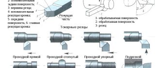
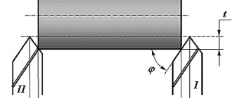
The force R is the vector sum of three forces: axial, tangential and radial. Their vectors are projections of the force vector R on the X, Y, Z axes. The figure below shows an image of the force vectors that arise during turning.
In technological calculations, it is not the force R itself that is used, but its components. Of these, the most significant and largest in magnitude is this tangential force Rz.
In practice, it is called cutting force, since it determines the power consumption and spindle torque. The cutting force is calculated using empirical formulas, data for which is taken from reference technological tables.
Calculation for turning is carried out using the following formula:
In addition to the constant Cp, power indices of feed, depth and cutting speed, the formula for calculating the cutting force includes a correction coefficient Kr. It is the product of five correction factors that take into account the processing characteristics of various materials.
Capacitive, inductive and strain gauge sensors are used to measure cutting forces in real time. The latter are the most compact and most accurate.
When used on CNC machines, the cutting force can be adaptively increased or decreased by automatically adjusting the feed rate and speed.
This allows continuous processing without operator intervention, and also prevents tool breakage and reduces tool wear.
Safety and tips
Before drilling a hole in metal, it is necessary to ensure safety measures. First of all, you need to pay attention to work clothes. It should not contain elements that could get under the rotating parts of the tool.
During operation, chips can fly in different directions. It is necessary to protect your eyes from it by wearing safety glasses. Before drilling itself, check how securely the part is secured in a vice or how tightly it fits to the surface of the workbench.
The drill, approaching the surface of the metal, should already be rotating. This avoids premature dulling. Also, do not stop the drill while removing the drill from the hole. You just need to slow down. Otherwise, the tool will either jam or break.
When the cutting edge penetrates into the metal with great difficulty despite the applied efforts, this indicates that the hardness of the machined surface is much greater than that of the tool. You need to take a drill with a carbide tip. And set the drill to the lowest speed.
Preparatory work
Preparatory work consists of eliminating some of the negative factors associated with drilling stainless steel. Let's look at what properties make this process difficult:
- The chemical composition of stainless steel grades helps to increase the ductility of the metal. When drilling such steels, chips stick to the drill, causing the cutting edges to be excluded from the process, and hardening forms on the walls inside the unfinished hole. Such surface hardening makes further processing difficult and changes the physical properties in this place.
- Heat is removed from the drill heated by rotation and cutting along the surface of the metal. Without taking preventive measures, you can end up with a tarnished area around the drilling. In addition to the damaged decorative surface, this reduces corrosion resistance and requires additional technological operations to restore the specified parameters.
To avoid the disadvantages described above, before drilling it is necessary to decide how the surface will be cooled and what to do to prevent chips from sticking. Among the effective methods, water is suitable. If the volume of metal being drilled is more than one hole with a diameter of 10 mm in a sheet of 2 mm thickness, then you should consider cooling with oil or a special emulsion.
Attention. Cooling with water when drilling stainless steel occurs during the process itself. Cooling by lowering a hot drill into a jar standing nearby leads to hardening and tempering of the metal and loss of basic properties. Coolant is supplied to the contact point when drilling. To reduce consumption, you can place a rubber ring on the surface, surrounding the contact point.
How to drill stainless steel at home?
When performing plumbing work on drilling stainless metal, professional drilling machines are not always at hand. Not every home master can boast of having specialized equipment. Therefore, below we will provide brief information on how to drill stainless steel at home.
The main disadvantage of working in such conditions is the impossibility of uninterrupted supply of lubricating fluid to the working area. Therefore, if it is necessary to obtain a hole on a horizontal surface, the following method is used. The workpiece is aligned strictly horizontally and secured. The location of the future hole is marked and marked to facilitate alignment. A piece of polymer or steel tube is installed on the hole. The internal diameter of such a tube should be slightly larger than the diameter of the drill. Then lubricating fluid is poured into the tube. If you do not have a special coolant, you can pour machine oil or even olive oil into the tube. Drilling must be done in this bath. If liquid splashes or spills, refill the bath.
If the hole needs to be made on a vertical surface, then liquid lubricant will not work. In this case, you can use a small piece of pork fat or paraffin, which I fix at the drilling site. When the drill and workpiece are heated, the lubricant will gradually melt and enter the drilling working area.