The main parameters defining cutting modes are:
-Spindle shaft rotation speed (n) -Feed speed (S) -Milling depth per pass
The required speed depends on:
-Type and characteristics of the spindle used -Cutting tool -Material being processed
The spindle speed is calculated using the following formula:
D – Diameter of the cutting part of the working tool, mm π – Pi number, 3.14 V – cutting speed (m/min) – the path traveled by the point (edge) of the cutting edge of the cutter per minute.
Cutting speed (V) is taken from reference tables (See below).
Please note that feed speed (S) and cutting speed (V) are not the same thing!!!
When calculating, for small-diameter cutters the value of the spindle rotation speed may turn out to be greater than the number of revolutions that the spindle is able to provide. In this case, the basis for further calculations of the value (n) is the actual maximum spindle speed.
Feed rate (S) – the speed of movement of the cutting tool (X/Y axis), calculated by the formula:
fz - feed per cutter tooth (mm) z - number of cutter teeth n - spindle speed (rpm) Feed per tooth is taken from reference tables for processing certain materials.
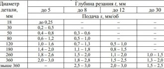
Table for calculating cutting conditions:
After theoretical calculations using formulas, it is necessary to adjust the value of the feed rate. The rigidity of the machine must be taken into account. For machines with high rigidity and mechanical quality, feed speed values are selected closer to the maximum calculated ones. For machines with low rigidity, lower feed rates should be selected.
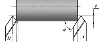
The milling depth per pass (Z axis) depends on the rigidity of the cutter, the length of the cutting edge and the rigidity of the machine. It is selected experimentally, during observation of the operation of the machine, by gradually increasing the cutting depth. If extraneous vibrations occur during operation and the resulting cut is of poor quality, the depth per pass should be reduced and the feed speed adjusted.
The vertical plunge speed (Z axis) should be selected at approximately 1/3 – 1/5 of the feed speed (S).
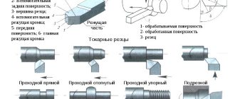
Brief recommendations for choosing cutters:
When choosing cutters, you need to take into account the following characteristics: -Diameter and working length. Cutter geometry. -Sharpening angle -Number of cutting edges -Material and workmanship of the cutter. It is best to give preference to cutters with a maximum diameter and minimum length for performing a specific type of work.
A short cutter with a large diameter has increased rigidity, creates significantly less vibration during intensive work, and allows for better quality of material removal. When choosing a large-diameter cutter, you should take into account the mechanical characteristics of the machine and the power of the spindle in order to be able to obtain maximum processing performance.
For processing soft materials, it is better to use cutters with an acute sharpening angle of the cutting edge; for hard materials, a more obtuse angle in the range of 70-90 degrees.
Plastics and soft materials are best processed with single-cut cutters. Wood and plywood - two-way. Ferrous metals – 3x/4x input. The material and quality of the cutter determine the service life, cut quality and modes. With low quality cutters it is difficult to achieve the calculated feed rates in practice.
Approximate cutting conditions used in practice.
This table is for informational purposes only. More precise processing modes are determined based on the quality of the cutters, the type of machine, etc. They are selected empirically.
Useful links:
Cutting modes
Milling business S. V. Avrutin
Creating a CP in the ArtCAM program
Choosing a cutter for a CNC machine
New items:
Flatbed plotters (vane, creasing, oscillating, tangential knife)
Machines with rotary spindle
Grinding
By means of a grinding tool, primary, secondary and finishing processing of workpieces is carried out. If the appropriate equipment is available, the master has access to a wide range of work:
- grinding the central part of the workpiece;
- internal and external grinding of centerless type;
- internal grinding using a chuck;
- flat grinding with the periphery or end of the tool;
- shaped grinding.
It is possible to sharpen cutting tools of various configurations.
When carrying out calculations, the rotation speed of the grinding wheels is taken into account. Incorrect use of this parameter will lead to the removal of excess material, premature tool wear and increased operation time.
Table 10. Rotation speed of the grinding tool during workpiece processing
The duration of operation of the wheels when performing various procedures also has a standardized value.
Table 11. Durability of grinding wheels
Cutting conditions depend on the grinding parameters and the specifics of the equipment used.
Table 12. Selection of cutting modes when working with abrasive tools
When working with threaded connections, special cutting conditions are used.
Table 13. Cutting conditions for thread grinding work
Sanding generates a lot of heat. Cooling liquids are used to disperse it. The use of 5 types of aqueous solutions is allowed:
- 1% soda ash and 0.15 sodium nitrite;
- 2-3% soda ash;
- 2% soap powder;
- 5-7% emulsol solution;
- 3.5% emulsol solution with the addition of oleic acid.
High-quality cooling will eliminate thermal deformation of the workpiece, prevent premature tool wear and disruption of processing technology.
Rice. 7 Operation of the abrasive wheel
For detailed information regarding abrasive tools, please visit the appropriate section of the catalog. It includes wheels, cloth- and paper-based abrasives, meshes and sanding accessories.
Influence of various factors on cutting forces
a) cutting conditions
Read also: Ice drill for fishing
As the cutting depth increases, the cross-sectional area of the cut layer increases, which causes an increase in all components of the cutting force. Moreover, the cutting depth has a stronger effect than the feed. The connection between Pz, Ru, Px иt, s is written in general form as follows:
, where xp > yp
Changing the cutting speed affects the cutting force components in the same way as it affects the chip shrinkage coefficient. When cutting materials that are not prone to build-up, cutting forces decrease monotonically with increasing speed; cutting (Fig. 31.).
b) geometric parameters
Rice. 31. Diagram of the influence of cutting speed on the build-up height H, chip shrinkage coefficient K and force P.
Cutting power and torque
Cutting power. The cutting work done in one second is called cutting power and is denoted by Np^.
In technology, power is expressed in kilowatts. In order for the machine to perform work, the power on the spindle L^shp must be equal to or greater than the power required for cutting, i.e. the condition must be met
The spindle receives power from the electric motor, while part of it is spent on overcoming frictional forces in the gearbox mechanism and is partially lost due to belt slippage. Therefore, the motor power is always greater than the spindle power.
The ratio of the spindle power A^ to the motor power NM is called the efficiency of the machine (Greek letter “eta”)
The efficiency factor (k, p.d.) shows what part of the electric motor power can be usefully used for cutting. For lathes with a gearbox, its average value is tj=0.7-0.8.
Efficiency is not a constant value for a given machine. With an increase in the number of revolutions, it decreases, so the power loss during idle operation of the machine increases. For specific calculations, the efficiency values should be taken from the machine’s passport.
When operating at low rpm, the power at the spindle is limited by the weak link in the transmission, which is usually one of the small gears, a slip clutch, or a V-belt drive. In this case, the cutting mode is checked by the power allowed by the weak transmission even.
Features of cutting hardened surfaces, as well as after surfacing.
Processing of restored parts. During the processing process, significant difficulties arise due to the special properties of the built-up layer (high hardness, uneven hardness along the length and depth of the layer, structural heterogeneity, the presence of non-metallic inclusions, etc.).
If the part is restored by various methods of automatic surfacing and remaining, then the material of the cutting part of the tool is made of hard alloys T5K10 and T15K6, the hardness of the pressed layer is less than 40 and VK8, VK6 and VK6M, NKS is more than 40. When processing the remaining surfaces, plates of hard alloy T30K4 are used The parts are treated using a coolant (emulsol 5...8%, technical soda ash 0.2%, the rest is water). Parts chrome-plated with smooth chrome are ground with electrocorundum wheels on a ceramic bond with a grain size of 40...50 and a hardness of C1...C2. The peripheral speed of rotation of the circle and the part is 30...40 m/s and 15...20 m/min, respectively.
After cooling, the parts are processed on lathes or grinders depending on the allowance, coating hardness, required accuracy and surface roughness. Coatings with a hardness HB < 200 are processed with conventional cutting tools, and with HB 400...450 - with carbide cutters and grinding. Coatings with a hardness of HB > 400...460 are ground with electrocorundum wheels on a bakelite bond with a grain size of 40...25 and a hardness of CM2...CM1.
In repair production conditions, in a number of cases it is necessary to sharpen parts made of hardened steel using carbide cutters of the VK and TK groups (VK8 and T15K6). For hardened steels, cutters with a negative rake angle (y = -10...-15°) and an inclination angle of the main cutting edge L = 5...10° are used. Sometimes the angle L reaches 45°. Cutting modes of hardened steels: V = 80… 120 m/min; 5″= 0.1…0.2 mm/rev., 1= 0.5…1 mm.
When turning parts made of hardened steel, they can take on a barrel-shaped shape due to the pressing of the caliper due to significant radial forces. Given the need to obtain greater accuracy, parts are processed in several passes. At the same time, the surface roughness is within the 7...8th class, therefore, this operation in some cases can be replaced by grinding.
As a result of the use of carbide coatings, the wear resistance of parts increases, but machinability also deteriorates significantly. Sometimes the coating cannot be used due to difficulties encountered during machining.
Rough boring of the PG-SR2 carbide coating is carried out with cutters with plates of VK6 and VKZ hard alloys. Their geometry: y = -8...-12°, main angle ph = 40...60°, auxiliary angle ph[ = 15...25″, rear angles a =a[= 13...15″ and A. = 0…10°. Rough boring mode: cutting depth 0.3...0.6 mm, feed 0.18...0.25 mm/rev., speed 25...35 m/min.
Calculation methods
Metal cutting conditions are calculated in one of two ways.
- Analytical. Calculations are made empirically. Specialists perform test operations based on cutting theory formulas. As a result, optimal processing modes are selected for a specific material or workpiece.
- Statistical. The processing method is selected according to the cutting modes directory. This approach does not involve conducting experiments and is focused on working with general industry standards.
The tool used must have a rational design, ensuring maximum use of all the capabilities of the equipment.
Countersinking
The geometry of the cutting part of countersinks is not standardized. Manufacturers use various technological solutions to improve efficiency and extend the service life of products.
When determining the cutting mode for steel with a countersink, specialists take into account the following parameters:
- back and front angle of the countersink;
- helical groove inclination angle;
- pommel angle;
- angle at which the cutting edge is inclined.
As is the case with other cutting tools, calculation procedures are performed according to basic formulas and recommendations of standards for cutting modes.
Rice. 4 Work of a countersink for metal
The section “Countersinks and countersinks” will help you become familiar with the tools for which technological cutting conditions are calculated. It offers a wide range of products and solutions for various processing options.