Information about the manufacturer of the 6P10 milling machine
The 6P10 milling machine was produced by the Vilnius Machine Tool Plant .
In 1947, the machine tool manufacturing plant produced its first products - 13 tabletop drilling machines.
In 1949, the development of more complex products began - cross-planing machines, followed by the production of horizontal, vertical and universal cantilever milling machines.
Machine tools produced by Vilnius Machine Tool Plant
- 6E80sh
- universal cantilever milling machine 200 x 800 - 6M80
- horizontal cantilever milling machine with rotary table (universal) 200 x 800 - 6N10
- vertical cantilever milling machine 200 x 800 - 6N80
- horizontal cantilever milling machine with rotary table (universal) 200 x 800 - 6N80G
- horizontal cantilever milling machine 200 x 800 - 6N80SH
- universal universal cantilever milling machine 200 x 800 - 6P80G
- horizontal cantilever milling machine 200 x 800 - 6Р10
- vertical cantilever milling machine 200 x 800 - 6Р80
- horizontal cantilever milling machine with rotary table (universal) 200 x 800 - 6R80G
- horizontal cantilever milling machine 200 x 800 - 6Р80Ш
- universal universal cantilever milling machine 200 x 800 - 6T10
- vertical cantilever milling machine 200 x 800 - 6T80
- horizontal cantilever milling machine with rotary table (universal) 200 x 800 - 6T80SH
- universal cantilever milling machine 200 x 800 - NS-12A
- tabletop drilling machine Ø 12 - SUS-1
desktop drilling machine Ø 12
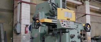
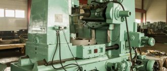
General view of the universal milling machine 6Р80Ш
Photo of milling machine 6р80ш
Photo of milling machine 6р80ш
Photo of milling machine 6р80ш
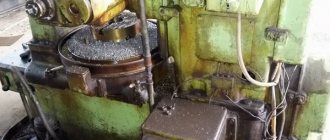
Photo of the console table of the milling machine 6р80ш
6P10 vertical cantilever milling machine for general purpose. Purpose, scope
The vertical cantilever milling machine 6P10 is designed for milling all kinds of parts from various materials.
The horizontal milling machine model 6Р80Г is the basic model, and the universal milling machine model 6Р80 and vertical milling machine model 6Р10 are its modifications.
Design features and operating principle of the machine
On a universal milling machine model 6P80, using a universal dividing head, you can mill spiral grooves on cylindrical parts, as well as perform various milling operations associated with rotating the part by a given amount.
The rotating milling head with a retractable sleeve of the vertical milling machine model 6P10 allows milling work on inclined surfaces of the part.
The overhead rotary milling head N80G.28 with a vertical spindle, available on special order for an additional fee, expands the technological capabilities of the 6R80G and 6R80 machines.
The machine is designed to perform various milling operations in single and batch production.
Roughness of the machined surface at finishing cutting conditions V 6.
Unlike previously produced machines of this type, the new machine is characterized by reduced noise, increased durability of the main components and preservation of accuracy standards for a longer period. The electrical equipment is mounted in a spacious niche and meets all modern requirements. Table feed control is separate. There are protective devices that protect the worker from chips and splashes of coolant. The cooling system is equipped with quick-release settling tanks. The appearance of the machine meets modern requirements of industrial aesthetics.
It is not possible to integrate the machine into an automatic line.
Machine accuracy class N.
6Р80Ш widely-universal console milling machine. Purpose and scope
The 6Р80Ш universal cantilever milling machine has been produced since 1972 of the last century. 6N80sh model in production
.
The 6Р80Ш milling machine belongs to the zero standard size of cantilever milling machines (the worktable size of the zero standard size is 200 x 800 mm) and is part of the series of milling machines: 6Р10
,
6Р80, 6р80г
.
6Р80Ш machine is designed for processing small parts made of steel, cast iron, non-ferrous metals and plastics.
A highly versatile console machine with a vertical rotating spindle, model 6Р80Ш, is designed to perform a variety of milling work in individual and mass production.
6Р80Ш machines are convenient for milling planes, ends, bevels, and grooves on small parts of various configurations.
Operating principle and design features of the machine
When delivering a machine model 6Р80Ш for export, the requirements for frequency, supply voltage and degree of automation must be taken into account in the design documentation and specified in the work order.
Type of climatic modification of the machine model 6Р80Ш УХЛ4 and Т according to GOST 15150-69.
The technical characteristics of the machines allow full use of the capabilities of tools made of high-speed steel, as well as tools equipped with carbide plates.
A rotating milling head with a retractable quill allows you to mill inclined surfaces of parts.
The use of a dividing head, a rotary table, a vice, and devices for linear division of the milling and slotting heads, supplied at the customer’s request for an additional fee, expands the technological capabilities of the machine mod. 6Р80Ш.
The machines operate on the principle of milling with a rotating cutter mounted in a horizontal or vertical spindle. The movements of the table (X coordinate), slide (Y coordinate), and console (Z coordinate) are used as working or installation movements.
The type of machine layout corresponds to the layout of cantilever milling machines of domestic and foreign production.
Design Features
The rack is the base unit on which all other units and mechanisms are mounted. The stand is rigidly connected to the plate (base), which is a coolant reservoir.
on the trunk of the 6Р80Ш , and hangers for working with long mandrels are attached to the trunk guides. The suspensions have a rolling support and a sliding support. The pendants on the machines are not interchangeable.
The horizontal spindle gearbox is mounted in a rack. The connection to the electric motor is via a poly-V belt drive.
The drive of the vertical spindle is carried out from an electric motor located on the top of the head, through a poly-V-belt drive, a roller clutch and a gearbox.
The spindle is mounted in a retractable sleeve.
The milling head of the machine is attached to the trunk with nuts and has the ability to rotate in the transverse and longitudinal directions of the table. The spindles contain ramrods for securing the cutting tool. Fastening is carried out mechanically from the clamping mechanism.
The feed drive is located in the console. The 18-speed feed box has an overdrive chain and a safety clutch, which eliminates the possibility of breakage of the feed drive due to overload.
The rear wall of the console is made in the form of dovetail guides.
The upper part of the console has rectangular guides along which the slide moves.
The slide moves laterally on the console and has table guides.
A longitudinal feed screw is connected to the table.
When working with the down milling method, a selection of gaps is provided between the threads of the lead screw and the nuts by turning the worm.
When working with the up-milling method, the lead screw wears out a lot. Therefore, when one job is being performed on the machine for a long time, the area of operation of the screw should be changed.
Machine accuracy class P according to GOST 8-77.
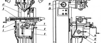
Location of components of the 6P10 cantilever milling machine
Location of components of the 6P10 milling machine
List of components of the 6P10 cantilever milling machine
- Console movement switching mechanism - 6Р80Г.42
- Slides of machines 6Р80Г and 6Р10 - 6Р80Г.50
- Table - 6Р80Г.51
- Bed of machines 6Р80Г and 6Р80 - 6Р80Г.10
- Trunk of machines 6Р80Г and 6Р80 - 6Р80Г.11
- Cooling of machines 6Р80Г and 6Р80 - 6Р80Г.60
- Cross feed nut - 6Р80Г.43
- Switching mechanism for moving the slide - 6Р80Г.42
- Electrical cabinet - 6Р80Г.70
- Main drive of machines 6Р80Г and 6Р80 - 6Р80Г.20
- Speed switching mechanism of machines 61Р80Г and 6Р80 - 6Р80Г.22
- Suspension of machines 6Р80Г and 6Р80 - 6Р80Г.16
- Suspension of machines 6Р80Г and 6Р80 - 6Р80Г.13
- Console - 6Р80Г.40
- Feed switching mechanism - 6Р80Г.32
- Feed box - 6Р80Г.30
- Machine bed - 6Р10 - 6Р10.10
- Cooling of the machine 6Р10 - 6Р10.60
- Main drive of the machine 6Р10 - 6Р10.20
- Machine speed switching mechanism 6Р10 - 6Р10.22
- Milling machine head 6Р10 - 6Р10.21
Description of the components of the milling machine 6Р80Ш
bed
The machine bed consists of a base, a stand and an electrical cabinet.
The following are installed on the base: a stand, a bracket with a nut for the console lifting screw and a cooling pump.
The internal cavity of the base is a reservoir for coolant.
On the right side of the rack there is an electrical cabinet, in the upper part there is a gearbox and a gear shift mechanism.
On the trunk of the 6R80G, 6R80 and 6R80Sh machines, hangers are attached (Fig. 17), which serve as supports for the milling mandrels. One of the 6R83G.13 suspensions has a rolling support, the second 6R80G.16 has a sliding support 1.
A special feature of the 6P10 machine bed is the presence of a flange in its upper part for attaching the spindle head.
Gearbox and spindle head
Gearbox for console milling machine 6р80ш
Vertical spindle head of console milling machine 6р80ш
The main drive chain of the 6R80G, 6R80, and 6R80Sh machines (Fig. 18) consists of an electric motor, a V-belt drive, a six-speed gearbox, a spindle and a gearbox built into the machine bed.
Double-row roller bearings with an inner ring seated on a cone are used as the front support of the spindle. To absorb axial forces, angular contact ball bearings are installed in the rear support. The gearbox of the 6P10 machine is shown in Fig. 19.
The spindle heads of the 6PI0 machine (Fig. 20) and the 6Р80Ш machine (Fig. 21) are mounted in retractable sleeves.
The adapter head of the vertical spindle of the 6Р80Ш machine is shown in Fig. 22.
Console and feed box
Feed box for console milling machine 6р80ш
A flange electric motor is built into the front, at the bottom of the console. On the left side of the console there is a feed box with a feed switching mechanism and a mechanism for turning on the vertical movement of the console, and on the right side there is a mechanism for moving the slide.
Twelve-speed gearbox (Fig. 23). In addition to the working feed chain, it has a rapid feed chain. The feed box contains a safety clutch 4, which eliminates the possibility of gear breakage during overload.
Electromagnetic clutch I and overrunning clutch 3 are mounted on the same shaft with the safety clutch. Rapid movements of the table, slide and console are activated by a button located on the front wall of the slide.
The handle and flywheel for manual movements of the table in the transverse and vertical directions are located on the front console (Fig. 24).
The console lifting mechanism is shown in Fig. 25.
The feed switching mechanism consists of a handle, a disk with profile grooves and levers. When the handle is moved up or down, the disc rotates and the levers move the forks and gears.
The mechanical movement of the console and slide is activated using handles located on the left and right sides of the console.
The direction of movement of the handles is mnemonically linked to the direction of movement of the console and slide.
The rear wall of the console is made in the form of dovetail profile guides.
On the right side behind the console there is a handle for securing the console to the stand.
The upper part of the console has rectangular guides along which the slide moves.
Table and slide
The slide moves laterally on the console and has table guides.
Screw 2 (Fig. 26) for longitudinal feed is connected to the table. The slide contains bevel gears 5 that rotate the screw, handle and mechanism for turning on the longitudinal feed of the table.
To work using the down milling method, a selection of gaps is provided between the threads of the lead screw 2 and nuts 3, 4 by turning the worm I.
When working with the up-milling method, the lead screw wears out a lot. Therefore, when one job is being performed on the machine for a long time, the area of operation of the screw should be changed.
The rotary slide on the 6P80 machine makes it possible to rotate the table within ±45° in the horizontal plane.
Trunk of the machine 6P80Ш
Speed switching mechanism of the vertical head of the 6р80ш cantilever milling machine
An electric motor and a gearbox (Fig. 27) with a gear shift mechanism (Fig. 28) are mounted in the trunk of the machine. The adapter head is attached to the trunk flange (Fig. 22) and the spindle head is attached to the latter (Fig. 21).
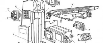
Location of controls for the 6P10 cantilever milling machine
Location of controls for the 6P10 milling machine
List of controls for the 6P10 cantilever milling machine
- Handle for manual console movement
- Handle for manual movement of the slide
- Vertical feed switch handle
- Button for enabling rapid movement of the table, slide and console
- Flywheel for manual table movement
- Backlash sampling worm in a table screw-nut pair
- Cooling tap
- Load indicator
- Power switch handle
- Light switch
- Signal lamp
- Stop button
- Slide Clamp Handle
- Cross feed switch handle
- Start button
- Console Clamp Handle
- Feed motor activation handle
- Electric cooling pump activation handle
- Spindle rotation direction switch
- Spindle Jog button
- Spindle override handle
- Spindle speed setting handle
- Trunk Clamp Screws
- Trunk movement shaft
- Longitudinal feed switch handle
- Table Clamp Screws
- Screws for clamping the rotary slide of the machine 6Р80
- Feed rate setting handle
- Machine spindle sleeve clamping handle 6P10
- Handle for moving the spindle sleeve of the machine 6P10
Technical description of vertical milling machine 6Р12
The technical description of the 6P12 vertical milling machine contains information necessary both for the operating personnel of this machine and for the employee directly involved in working on this machine. This manual is an electronic version in PDF format of the original paper version with some chapters missing.
You can download the “Technical description of the 6P12 vertical milling machine” for free in good quality from the link below:
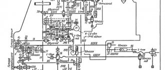
Kinematic diagram of the 6P10 cantilever milling machine
Kinematic diagram of the 6P10 milling machine
Limits of use of 6P10 machines
Limits of use of machines The full value of the strokes indicated in the passport can be used only if there are no parts or devices on the machine table that limit the movement of the table. For example, when using a round rotary table and installing a mandrel with a cutter in the spindle, the vertical stroke of the table is reduced; when installing a dividing head with a guitar, the longitudinal travel of the table is reduced; When installing workpieces between the table and the frame mirror, the transverse movement of the table is reduced.
To use full mechanical movements of the table, it is necessary to set the switch stops to their extreme positions. In this case, it is necessary to monitor the operation of the moving parts of the machine to eliminate the possibility of their breakdown.
When working with a mechanical drive, the dividing head is installed at the right end of the table. The dividing head spindle receives rotation from the table lead screw through the guitar's replaceable gears, for installation of which it is necessary to remove the protective bracket at the right end of the table.
Operating mode of the machine 6Р10
At high and medium spindle speeds, the limits of machine use are limited mainly by the permissible cutting speeds for cutters and the power of the main motion electric motor.
If vibrations occur in some modes, it is recommended to change the feed rate per tooth or use cutters with an uneven pitch and a large angle of inclination of the chip flutes.
Working with end mills on steel
- Cutter diameter - 80 mm
- Number of cutter teeth - 16
- Milling width - 40 mm
- Milling depth - 3 mm
- Spindle speed per minute - 140 rpm
- Cutting speed - 35 m/min
- Feed – 280 mm/min
- Feed per tooth - 0.12 mm
To achieve high surface cleanliness and high dimensional accuracy when working with high-speed steel cutters, it is recommended to work at a feed per tooth S = 0.02..0.03 mm, with a milling depth t = 0.3..0.5 mm and cutting speed V = 17..25 m/min.
Kinematic diagram of the 6Р80Ш milling machine
Kinematic diagram of the milling machine 6р80ш
Kinematic diagram of the milling machine 6р80ш
Kinematic diagram (Fig. 14, 15, 16)
The main movement is driven by an electric motor through a V-belt transmission and a gearbox. By moving the gear blocks on shaft II and switching the selection gears on the spindle, we obtain 12 speeds.
The feed is driven by an electric motor mounted in the console.
Rotation from the feedbox shaft XIII is transmitted to the console shaft XIV.
The kinematic chain of accelerated movements of the table comes from the electric motor through shafts VIII, IX, X, XIII, electromagnetic clutch, overrunning clutch and console shaft XIV.
The inclusion and reversal of longitudinal, transverse and vertical feeds is carried out by double-sided cam clutches 25, 32, 39.
List of kinematic diagrams (see Table 4).
Design and operation of the 6P10 machine
Main drive of the 6P10 machine
The kinematic diagrams of the main drive of the 6R80G and 6R80 machines are the same. The spindle rotates from an electric motor through a V-belt transmission and a gearbox. When moving gear blocks on shaft II-II and switching gears on the spindle, 12 speeds are obtained.
The kinematic diagram of the main drive of the 6P10 machine is similar to that of the 6P80G and 6P80 machines, only the drive is located on a separate shaft and, together with the spindle, is built into the milling head.
Feed drive of the machine 6Р10
The kinematic diagram of the feed drive is the same for all machines. The rotation of the feed drive shafts VIII, IX, X, XI, XII, XIII is carried out by an electric motor.
Working feed is carried out with the electromagnetic clutch turned off. The rotation from the feed box is transmitted through the overrunning clutch to the XIV console shaft.
The kinematic chain of accelerated movements of the table comes from the electric motor through shafts VIII, IX, X, XIII, electromagnetic clutch, overrunning clutch and console shaft XIV.
The inclusion and reversal of longitudinal, transverse and vertical feeds is carried out by double-sided cam clutches 25, 32, 39.
Machine bed 6Р10
The machine bed consists of a base, a stand, an electrical cabinet, a casing and a trunk with hangers (on the 6P10 machine there is no trunk and hangers).
The following are installed on the base: a stand, a bracket with a nut for the console lifting screw and a cooling pump.
The internal cavity of the base is a reservoir for coolant.
An electrical cabinet is attached to the right side of the rack, and a gearbox and gear shift mechanism are located in the upper part.
Suspensions are attached to the trunk of the 6R80G and 6R80 machines, which serve as supports for the milling mandrels. One of the suspensions has a rolling support, the other has a sliding support.
A special feature of the 6P10 machine bed is the presence of a flange in its upper part for attaching the milling head.
Gearbox and spindle of the 6P10 machine
Gearbox for console milling machine 6р10
The spindle drive of the 6R80G and 6R80 machines consists of an electric motor, a V-belt drive, a six-speed gearbox, a spindle and a gearbox, built into the machine assembly.
Double-row roller bearings with the inner ring seated on a cone are used as the front support of the spindle. To absorb axial forces, angular contact ball bearings are installed in the rear support.
The spindle drive of the 6P10 machine is distinguished by the presence of a bust shaft and a retractable sleeve located in the milling head housing.
Console and feed box of the 6P10 machine
Feed box for console milling machine 6р10
The feed drive is located in the console. A flange electric motor is built into the front, in the lower part of the console; a feed box with a feed switching mechanism and a mechanism for enabling vertical movement of the console is mounted on the left side of the console, and a mechanism for moving the slide is mounted on the right side.
In addition to the working feed chain, the 12-speed gearbox has a rapid feed chain. The feed box contains safety clutch 1 (Fig. 15), which eliminates the possibility of gear breakage due to overload.
An electromagnetic clutch 2 and an overrunning clutch 3 are mounted on the same shaft with the safety clutch. The fast movements of the table, slide and console are activated by a button located on the front wall of the slide.
The handle and flywheel for manual movement of the table in the transverse and vertical directions are located on the front console.
The feed switching mechanism consists of a handle, a disk with profile grooves and levers. When the handle is moved up or down, the disc rotates and the levers move the forks and gears.
The mechanical movement of the console and slide is activated using handles located on the left and right sides of the console. The direction of movement of the handle is mnemonically linked to the direction of movement of the console and slide.
The rear wall of the console is made in the form of dovetail profile guides.
On the right side behind the console there is a handle for securing the console to the stand.
The upper part of the console has rectangular guides along which the slide moves.
Table and slide of machine 6Р10
The slide moves laterally on the console and has table guides.
Screw 1 (Fig. 18) for longitudinal feed is connected to the table. The slide contains bevel gears 2 that rotate the screw, handle and mechanism for turning on the longitudinal feed of the table.
To work with the down milling method, a mechanism is provided for sampling the gaps between the threads of the lead screw 1 and nuts 3 and 4.
When working with the up-milling method, the lead screw wears out a lot. Therefore, when one job is being performed on the machine for a long time, the area of operation of the screw should be changed.
The rotary slide on the 6P80 machine makes it possible to rotate the table within ±45° in the horizontal plane.
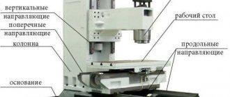
Design and overall dimensions
This device consists of several working elements, among which are:
- gearbox;
- bed;
- trunk;
- table with slide;
- brackets with nuts;
- machine dimensions mm – 1600x1875x2080.
Description and location of components
The bed is the main part of the device, which is mounted on the base and other mechanisms are fixed to it. The stand is connected to the base, which in turn acts as a reservoir for coolant. The cutting head is installed on the trunk, and the trunk itself is attached to the table.
The hangers have a support, and to install the head, you need to unfold the mount. The gearbox is located in the frame itself. It is connected to the engine via a belt drive. For inspection and maintenance of the unit there is a window on the left side of the frame. The vertical spindle drive is powered by an electric motor, which is located at the top of the head. Torque is transmitted through a clutch and belt drive, and the user can select speeds. The table is installed on a retractable slot.
Controls
On the left side of the machine there is a gearbox control lever, as well as a button to turn the device on/off. In the same part of the body there are levers for controlling the movement of the table and cutting head.
Kinematic diagram
Electrical diagram
Electrical equipment
Depending on the voltage in the network to which the equipment is connected, it can be designed for use in networks with a frequency of 50-60 Hertz and a voltage of 220-500 V.
Important!
The choice of the operating voltage of the network, as well as equipping the device with the appropriate components, is made by the customer. Information about this is additionally provided when accepting an order for the manufacture of equipment or its stand.
The device can be equipped with asynchronous electric motors:
- M1.
- M2.
- M3.
Electrical equipment of milling machine 6Р10
The electrical equipment installed on the machine is designed for a power circuit voltage of 380 V, 50 Hz three-phase alternating current. The following voltages are used in the control circuit:
- magnetic starter circuit ~ 110 V
- electrodynamic braking circuit ~ 55 V
- electromagnetic clutch circuit - 24 V
- local lighting circuit ~ 36 V
- signal lamp circuit ~22 V
The machine is equipped with three three-phase squirrel-cage asynchronous electric motors. Technical data of electric motors are given in the list of electrical devices attached to the circuit diagram.
Description of the operation of the electrical circuit of the 6P10 milling machine
By turning on the input circuit breaker A1, mains voltage is supplied to terminals A10, B10, C10, i.e., to the primary windings of control transformers TU1, TU2, TUZ and to the input contacts of the magnetic starter CL.
The machine is put into operation by pressing the KU2 button (symbol !). In this case, the CL magnetic starter is triggered, which, having closed its closing contacts in the power circuit, turns on the electric motors of the spindle drive DS, feed drive DS and electric pump BS.
For separate operation of electric motors ДШ, ДП, ДО there are, respectively, switches ПШ, ВП, ВН. In addition, the PSh switch is designed to change the direction of rotation of the DSh electric motor.
The machine is stopped by pressing the KU1 button (symbol O). By pressing the latter, the CL magnetic starter is turned off, which, in turn, turns off all electric motors.
When the KU1 button is pressed, the magnetic starter CT is turned on by the closing contact, which, together with the intermediate relay RP, by closing its closing contacts in the braking circuit, supplies direct current to the electric motor stator circuit. Electrodynamic braking of electric motors occurs. The duration of braking is determined by the pressed state of the KU1 button.
To turn on the accelerated movement of the table, there is a button KU4 (symbol), by pressing which, when the magnetic starter CL is turned on, the electromagnetic clutch MBH is turned on.
For short-term activation of electric motors there is a KUZ button (symbol T).
To turn on local lighting, switches B01, B02 are installed on the lamps.
Protection, blocking and signaling of the 6P10 milling machine
Protection of the electrical equipment of the machine from short circuits in the power circuit is carried out by automatic switches A1, A2 and in control circuits - by automatic switch A3 and fuses Pr1 - PrZ.
Overload protection of the spindle drive electric motors and the electric pump is carried out, respectively, by thermal relays RT1 and RT2. Overload protection of the DP feed drive electric motor is carried out by automatic switch A2.
Minimum protection of electric motors is provided by a CL magnetic starter.
The inability to turn on the electric motors when the rear door of the machine is open is ensured by the VK limit switch.
When the handle of the input switch is in the on position, it is impossible to open the door of the electrical cabinet, and when the door is open, the handle of the input switch cannot be turned on. This blocking is ensured by the design of the input switch handle. If it is necessary to turn on the input switch with the electrical cabinet door open for repair purposes, you must press rod E (Fig. 5 and 6), which extends when the door is opened.
The presence of mains voltage in the electrical circuits of the machine when the input circuit breaker A1 is turned on is indicated by the LS signal lamp.
After the input switch automatically turns off, its handle remains in the “on” position. The signal lamp then goes out. To turn it on again, you need to move the handle to the “Off” position and then switch it to the “on” position.
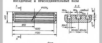
Technical characteristics of the cantilever milling machine 6P10
| Parameter name | 6Р80г | 6Р80 | 6Р10 | 6Р80Ш |
| Basic machine parameters | ||||
| Accuracy class | N | N | N | P |
| Dimensions of the working surface of the table, mm | 800 x 200 | 800 x 200 | 800 x 200 | 800 x 200 |
| Distance from the spindle axis to the table surface, mm | 50..350 | 50..350 | — | 50..350 |
| Distance from the end of the spindle to the table surface, mm | — | — | 50..350 | 50..350 |
| Maximum distance from the end of the spindle to the shackle bearing, mm | 450 | 450 | — | 350 |
| Distance from the spindle axis to the trunk, mm | 123 | 123 | — | 123 |
| Distance from the rear edge of the table to the vertical guides of the frame, mm | 80..240 | 80..240 | 80..240 | 80..240 |
| Distance from the spindle axis to the vertical guides of the bed (overhang), mm | — | — | 265 | — |
| Spindle | ||||
| Horizontal spindle rotation speed, rpm | 50..2240 | 50..2240 | — | 50..2240 |
| Vertical spindle rotation speed, rpm | — | — | 50..2240 | — |
| Number of horizontal and vertical spindle speeds | 12 | 12 | 12 | 12 |
| Movement of the spindle quill (sleeve), mm | — | — | 60 | 60 |
| Movement of the spindle quill by one dial division, mm | — | — | 0,05 | 0,05 |
| Angle of rotation of the milling head in the longitudinal plane, degrees | — | — | ±45° | ±90° |
| End of horizontal spindle according to GOST 836-72 | 40 | 40 | — | 40 |
| End of vertical spindle according to GOST 836-72 | 40 | 40 | — | 40 |
| Milling head spindle | ||||
| Angle of rotation of the milling head in the transverse plane, degrees | — | — | — | +30°-45 |
| Inner taper of milling head spindle | — | — | — | Morse 4 |
| Milling head spindle rotation speed, rpm | — | — | — | 56..2500 |
| Number of spindle speeds of the milling head | — | — | — | 12 |
| Table. Table feed | ||||
| Maximum longitudinal stroke of the table (X), mm | 500 | 500 | 500 | 500 |
| Maximum transverse travel of the table (Y), mm | 160 | 160 | 160 | 160 |
| Maximum vertical travel of the table (Z), mm | 300 | 300 | 300 | 300 |
| Limits of table rotation, degrees | — | — | ±45° | — |
| Limits of longitudinal table feeds (X), mm/min | 25..1120 | 25..1120 | 25..1120 | 25..1120 |
| Limits of table cross feeds (Y), mm/min | 25..1120 | 25..1120 | 25..1120 | 25..1120 |
| Limits of vertical table feeds (Z), mm/min | 12,5..560 | 12,5..560 | 12,5..560 | 12,5..560 |
| Number of table feed stages (longitudinal, transverse, vertical) | 12 | 12 | 12 | 12 |
| Speed of fast movements (longitudinal, transverse/vertical) X, Y/ Z, m/min | 2,3/ 2,3/ 1,12 | 2,3/ 2,3/ 1,12 | 2,3/ 2,3/ 1,12 | 2,3/ 2,3/ 1,12 |
| Movement of the table by one dial division (longitudinal, transverse/vertical), mm | 0,05/ 0,02 | 0,05/ 0,02 | 0,05/ 0,02 | 0,05/ 0,02 |
| Table movement per one revolution of the dial (longitudinal, transverse/vertical), mm | 6/ 2 | 6/ 2 | 6/ 2 | 6/ 2 |
| Maximum permissible cutting force (longitudinal/transverse/vertical), kg | ||||
| Machine mechanics | ||||
| Feed stops (longitudinal, transverse, vertical) | Eat | Eat | Eat | Eat |
| Blocking manual and mechanical feeds (longitudinal, transverse, vertical) | Eat | Eat | Eat | Eat |
| Blocking separate feed switching | Eat | Eat | Eat | Eat |
| Spindle braking | Eat | Eat | Eat | Eat |
| Overload safety clutch | Eat | Eat | Eat | Eat |
| Electrical equipment and machine drives | ||||
| Number of electric motors on the machine | 3 | 3 | 3 | 4 |
| Electric motor of main movement ДШ, kW (rpm) | 3,0 (1430) | 3,0 (1430) | 3,0 (1430) | 3,0 (1430) |
| Electric feed drive motor DP, kW (rpm) | 0,8 (1360) | 0,8 (1360) | 0,8 (1360) | 0,8 (1360) |
| Coolant pump electric motor, kW (rpm) | 0,12 (2800) | 0,12 (2800) | 0,12 (2800) | 0,12 (2800) |
| Electric motor of the milling head DG, kW (rpm) | — | — | — | 1,1 (1400) |
| Total power of all electric motors, kW | ||||
| Dimensions and weight of the machine | ||||
| Machine dimensions (length width height), mm | 1525 x 1875 x 1515 | 1525 x 1875 x 1515 | 1435 x 1875 x 1750 | 1820 x 1875 x 1765 |
| Machine weight, kg | 1240 | 1260 | 1270 | 1340 |
- Cantilever milling machines 6Р80Г, 6Р80, 6Р10, 6Р80Ш. Operating manual 6Р80Г.00.000 РЭ, 1978
- Console milling machines 6Р80Г, 6Р80, 6Р10. Operating manual 6Р80Г.00.000 РЭ, 1974
- Console milling machines 6Р80Г, 6Р80, 6Р10. Operating manual for electrical equipment 6Р80Г.00.000 РЭ1, 1974
- Avrutin S.V. Fundamentals of Milling, 1962
- Avrutin S.V. Milling, 1963
- Acherkan N.S. Metal-cutting machines, Volume 1, 1965
- Barbashov F.A. Milling business 1973, p.141
- Barbashov F.A. Milling work (Vocational education), 1986
- Blumberg V.A. Milling machine handbook, 1984
- Grigoriev S.P. Practice of coordinate boring and milling work, 1980
- Kopylov R.B. Working on milling machines, 1971
- Kosovsky V.L. Handbook of a young milling operator, 1992, p. 180
- Kuvshinsky V.V. Milling, 1977
- Nichkov A.G. Milling machines (Machinist's Library), 1977
- Pikus M.Yu. A mechanic's guide to repairing metal-cutting machines, 1987
- Plotitsyn V.G. Calculations of settings and adjustments of milling machines, 1969
- Plotitsyn V.G. Setting up milling machines, 1975
- Ryabov S.A. Modern milling machines and their equipment, 2006
- Skhirtladze A.G., Novikov V.Yu. Technological equipment for machine-building industries, 1980
- Tepinkichiev V.K. Metal cutting machines, 1973
- Chernov N.N. Metal cutting machines, 1988
- Frenkel S.Sh. Handbook of a young milling operator (3rd ed.) (Vocational education), 1978
Bibliography:
Related Links. Additional Information
- Milling machines: general information, classification, designation
- Comparative characteristics of cantilever milling machines of the 6N, 6M, 6R, 6T
- Feed box for console milling machines of the 6M : 6M12P, 6M13P, 6M82, 6M83, 6M82Sh, 6M83Sh
- Feed box for console-milling machines of the 6P : 6Р12, 6Р13, 6Р82, 6Р83, 6Р82Ш, 6Р83Ш Feed box for console-milling machines of the 6Т : 6T12, 6T13, 6T82, 6T83, 6Т82Ш, 6Т83Ш
Electrical equipment of milling machines of the Gorky Machine Tool Plant, GZFS
Electrical equipment of milling machines of the Vilnius Zalgiris Machine Tool Plant
Specifications
The main ones are:
- manufactured according to GOST 165 581;
- accuracy class – P;
- working surface (length/width) – 200x800 mm;
- distance from spindle to table - 0.4 mm;
- maximum cutter diameter - 100 mm;
- the work table moves longitudinally by 560 mm;
- maximum workpiece width – 800/260/450 mm;
- spindle speed - 2500 rpm;
- number of spindle speeds – 12;
- maximum spindle torque 155/117 rpm depending on the location of the head;
- machine weight 1430 kg;
- power 3 kW.