Here are useful formulas and definitions needed for milling: machining process, cutters, milling methods, etc. Knowing how to correctly calculate cutting speed, feed per tooth, and metal removal rate is critical to obtaining good results in any milling operation.
| Parameter | Meaning | Metric units | Inch units |
| ae | Milling width | mm | inch |
| ap | Axial cutting depth | mm | inch |
| DCap | Cutting diameter at cutting depth ap | mm | inch |
| Dm | Processable diameter (part diameter) | mm | inch |
| fz | Feed per tooth | mm | inch |
| fn | Feed per revolution | mm/rev | inch |
| N | Spindle speed | rpm | rpm |
| vc | Cutting speed | m/min | ft/min |
| ve | Effective cutting speed | mm/min | inch/min |
| vf | Minute feed | mm/min | inch/min |
| zc | Effective number of teeth | PC. | PC. |
| hex | Maximum chip thickness | mm | inch |
| hm | Average chip thickness | mm | inch |
| kc | Specific cutting force | N/mm2 | N/in2 |
| PC | Power consumption | kW | hp |
| Mc | Torque | Nm | lbf/ft |
| Q | Metal removal rate | cm3/min | inch3/min |
| KAPR | Main plan angle | hail | |
| PSIR | Leading Angle (inch) | hail | |
| BD | Case diameter | mm | inch |
| DC | Cutting diameter | mm | inch |
| L.U. | Working length | mm | inch |
The essence of the process
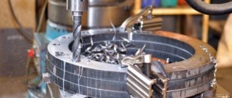
Milling is a procedure carried out on special machine equipment. During it, a layer (surface or deep, internal part) is removed from the workpiece. During it, various materials can be used, the most popular of which are wood or metal, so we are mostly talking about metalworking.
How the process works. The workpiece is fixed on the bed. Select a suitable cutter or abrasive material, such as a grinding wheel. The equipment produces rotational movements around its axis, as well as movements along two planes. At the same time, longitudinal advancement of the workpiece towards the cutter is possible.
The difference from a lathe is that a milling machine involves rotating the part, that is, circular processing. And in this case, you can grind products of almost any shape, including grinding a smooth surface, making grooves and other holes, including shaped ones. Metalworking can be of two types - rough and finishing. Of course, there are many more stages, but, as a rule, 2 or 3 passes are made. This allows you to create the desired surface profile, such as grooves or teeth.
The movement of the working tool is intermittent. An interesting feature that distinguishes milling from drilling or turning is the position of each tooth during the machining process. They work, come into contact with the surface one at a time, and not all together. This increases the load on each of the edges of the cutter. And only optimization of cutting conditions during milling will help minimize the impact.
Properties of stainless steels that complicate milling
Characteristics that make it difficult to process workpieces by cutting include:
Self-strengthening during deformation, called “hardening”. When the cutting edge of the cutter is pressed, the metal is deformed, as a result of which its hardness increases. If another pass is required, the tool will need to cut away the highly hardened layer. One of the reasons that causes this problem is an incorrectly selected and worn tool. Reduced thermal conductivity, making it difficult to remove heat from the cutting zone. The workpiece and chips absorb a small part of the heat, and the rest is transferred to the tool, which reduces its service life due to intense wear. High hardness and strength provided by alloying elements - nickel, titanium and others. When processing such material, the cutter experiences much greater loads compared to the process of cutting conventional carbon steels. Therefore, the tool quickly fails. Metal adhesion to the edge of the cutter. This leads to a violation of its geometry and an increase in cutting force. Difficult chip crushing and the formation of burrs on the workpiece. These problems are especially relevant in cases of incorrect selection of tools.
Basic concepts about the operation of milling machines
Equipment can be completely different; the main classification depends on the plane in which the working area is located. In this regard, a distinction is made between vertical and more common horizontal frames. Accordingly, the location of the spindle and fasteners will be different. According to their specifications, there are universal (multifunctional) machines, as well as specialized ones, for example:
- to form smooth planes;
- for cutting figured grooves;
- gear cutting equipment (creating gear connections) and so on.
These were listed examples when working on metal. And for wood - manual, stationary, spindle and drum (they are very dangerous, so they are rarely used now, but they are very effective).
Separately, it is worth mentioning those machines that are equipped with a numerical control panel (CNC). They have the following advantages:
- Ease of operation: the operator does not need to make many movements, you can only observe and control the actions.
- The program independently calculates the optimal motion pattern and cutting mode during milling. This will be the shortest route for moving the cutter with maximum efficiency.
- Increased cutting accuracy. Here are the minimum permissible errors, which cannot be compared with those that occur during mechanical, manual processing.
Returning to simpler machines, let's see what main components it has:
- Bed. It is strong and should withstand almost any load. It includes a built-in gearbox. This block is designed to regulate the rotation of a vertically standing spindle, as well as the cutter that is mounted on it.
- Table with cross runners. Workpieces that are subject to longitudinal movement are attached to it. Also at the bottom there is an object responsible for feeding. It includes different handles to determine movements.
Versatility increases if a rotary table is present - there are more functions that can be performed on milling equipment. In addition, the highly versatile devices additionally have two spindles, which makes it possible to implement various milling technologies.
Milling inclined planes with cylindrical end mills
Two technologies are used for milling inclined planes with end mills.
Milling with workpiece rotation
This technology involves the use of a universal rotary vice. The blanks are fastened in them in the same way as in regular ones.
Image No. 15: milling an inclined plane with an end mill and rotating the workpiece
Important! The inclined plane to be processed should be parallel to the table.
Milling with machine spindle rotation
This is possible on both vertical and horizontal milling machines. To do this, the former must have the function of rotating the headstock with the spindle around a horizontal axis, and the latter must have overhead vertical heads. For milling, simply set the desired angles of inclination.
Image #16: Milling an inclined plane with a 60° end mill
The classification of cutters depends on the purpose of cutting modes during milling
There are more than 1000 different types of cutters, which can be divided according to numerous parameters and sizes. Its choice directly depends on the rules of movement (rotation speed, direction, presence of counter feed and its power) of the tool. They are also directly determined by the type of metalworking - roughing or finishing. So, let's look at what classifications are carried out:
- according to the workpiece material - there are separate cutters for metal (different for different alloys), wood, plastic and other synthetic substances;
- in the direction of rotation - right-handed and left-handed, by the way, the ease of chip removal depends on this;
- according to design features - alloy, monolithic, folding with the ability to replace cutting parts, etc.;
- in shape - there is a lot of variety here, so listing them all is almost pointless; note that there are round, cylindrical, and conical disk cutters;
- according to the material of manufacture - it can be tool or high-speed steel, carbide metal, carbon or other alloys;
- by purpose - the largest division, which should include end, end, cutting, shaped, and so on.
When choosing the recommended cutting mode, you should especially pay attention to what material the cutting edge is made of, as well as what the cutter is intended for.
Recommendations when choosing a mode
It is almost impossible to select an ideal processing mode, but there are a number of recommendations that it is advisable to follow:
- The diameter of the tool must correspond to the working depth. This allows machining to be carried out in one pass, but for materials that are too soft there is a risk of removing chips that are thicker than necessary.
- Due to shock and vibration, it is advisable to start with a feed of about 0.15 mm per tooth and then adjust up or down.
- It is not advisable to use the maximum number of revolutions; this may lead to a drop in cutting speed. The frequency can be increased by increasing the diameter of the tool.
Determining the cutting mode is done not only using tables. Knowledge of the features of the machine and the personal experience of the milling operator play a big role.
Up and down milling
As we noted above, there are two feeds - this is the movement of the cutter itself, as well as the movement of the workpiece. Accordingly, in relation to each other they can be:
- Co-directional. This results in an increased load on the teeth, and accordingly, their wear accelerates. In this case, the power is reduced by an average of 10% of the second type of movement. This is the optimal solution and suitable mode for the finishing stage of metalworking.
- Multidirectional, that is, both feeds (cutter and workpiece) are arranged towards each other. The teeth of the equipment gradually, one by one, cut into the material; it is believed that in this case the mechanical force on each cutting edge is distributed gradually and in proportion to the speed. But this technology is not suitable for the finishing stage of work, because hardening may form during it. This is done at the moment of contact of the cutter with the surface due to the opposite direction. This phenomenon will not only make the cut unsightly, but will also increase the wear rate of the working tool. Therefore, this method is mainly used for primary (roughing) or rough processing.
Definitions for cutters
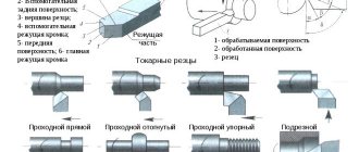
Principal plan angle (kr), degrees.
The leading angle (kr) is the main geometric parameter of the cutter, as it determines the direction of the cutting force and the thickness of the chip.
Cutter diameter (Dc), mm
The diameter of the cutter (Dc) is measured through the point (PK) where the main cutting edge intersects the parallel chamfer.
The most informative parameter is (Dcap) - the effective cutting diameter at the current cutting depth (ap), it is used to calculate the cutting speed. D3 is the maximum diameter of the inserts; for some types of cutters it is equal to Dc.
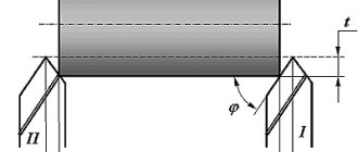
Depth of cut (ap), mm
Depth of cut (ap) is the distance between the machined and uncut surfaces, measured along the axis of the cutter. The maximum ap value is limited mainly by the insert size and machine power.
When performing rough operations, the amount of transmitted torque is essential. At the finishing stages of processing, the presence or absence of vibrations becomes more important.
Milling width (ae), mm
The milling width (ae) is the amount of allowance to be cut, measured in the radial direction. This parameter is especially important when plunger milling. The maximum value of ae also plays a significant role in the occurrence of vibration in corner milling operations.
Overlapping width (ae/Dc)
The overlap width (ae/Dc) is the ratio of the milling width to the cutter diameter.
Effective number of cutter teeth (zc)
This value is used to determine the minute feed (vf) and productivity. This often has a decisive impact on chip evacuation and machining stability.
Number of cutter teeth (zn)
The value is selected taking into account compliance with the condition of uniformity of the milling process. It is the number of passes that determines the type of milling, the group of materials to be processed and its rigidity.
Cutter tooth pitch (u)
For a certain cutter diameter, you can choose different tooth pitches: coarse (L), normal (M), fine (H). The letter X in the cutter code indicates a particularly fine tooth pitch
Basic concepts about cutting modes, milling on CNC machines
This is more advanced equipment that has a numerical control unit. That is, an embedded computing device (computer) with software. It, that is, the software, is aimed at determining the appropriate processing speed, selecting the desired direction of rotation, as well as the trajectory of the cutter. The main task of CNC installation is process automation. Therefore, the operator only observes during milling. This significantly reduces the number of defects, because there is no human factor, which often leads to errors.
In addition to the accuracy of the workflow and automatic mode selection, it is also worth noting increased productivity. Simply put, it will not replace the work of three, or even more mechanical, hand-held devices. And this despite the fact that the work of a milling machine operator is much harder, and the possibility of defects or injury is higher.
The most common machines used on CNC are face or end mills. They are quite versatile and have a wide range of purposes. But there are many standard sizes, the required subtype can be selected according to a number of parameters, these are:
- the type of chips that are formed;
- software parameters;
- strength of the processed material, etc.
Milling cutters of this category differ in the number of passes (the most popular are double-pass), which leads to chip removal and the presence of sharp edges. If the material is soft (for example, wood), and the chips are long and wide, then it is typical to use a fast cutting mode when milling wood using a single-cut tool. Multi-pass, on the contrary, will be needed when hard metals are processed (then the chips come out not monolithic, but as if broken).
Manufacturing of dentures using milling method
Today, CAD\CAM technologies are often used to manufacture modern dentures.
Having started in industry several years ago, they are successfully used in dentistry today. Their essence lies in computer design and subsequent automatic production of prostheses. The technology makes it possible to produce an individually shaped prosthetic bed. There are two methods for making prosthetics using computers:
- Subtraction method (everything unnecessary is removed from a block of material);
- Addition method (the prosthesis is built in layers).
Let us list the main advantages of CAD/CAM milling systems:
- Maximum accuracy (edge fit - up to 20-30 microns);
- Possibility of using innovative materials;
- High production speed;
- Compact dimensions of the equipment.
The milling method can be used to make models of individual dentitions and entire jaws if preceded by an intraoral or impression scan. The same technology is successfully used to produce navigation templates.
Speed
Moving directly to the parameters, it is worth noting that this one is the most important. It characterizes the period of time over which a certain layer will be removed from the surface. Some milling operators who do not have a wide range of tasks are accustomed to single-speed mode. Others, correctly, change it depending on the material:
- Stainless steel has a very low machinability rate. This is due to alloying additives in the steel. Therefore, you should not exceed the interval from 45 to 95 meters per minute.
- Bronze is much softer, so it can cut up to 150 m/min.
- Brass allows you to work in large ranges - from 130 to 320 meters per minute. However, be careful - with a significant increase in heating, the material becomes very plastic, which can lead to deformation.
- There are several aluminum alloys; when calculating cutting conditions for a milling operation, it is necessary to determine the specific composition of aluminum. That’s why the boundaries are so wide – from 200 to 420 m/min.
When setting the mode, the number of rotation revolutions per unit of time is set; they can be calculated using the formula:
n=1000 V/D, where:
- V is the recommended processing speed (see it in the table below);
- D is the diameter of the cutter, it can be recognized by the corresponding markings on the tool.
Experienced milling operators give a recommendation: do not drive the spindle at high speeds, because with such intensive work the machine wears out very quickly. It is better to calculate the cutting mode when milling according to the specified formula and remove another 10-15 percent from the obtained result. How fast the tool rotates depends on:
- Processing quality. For example, the peeling will be characterized by significantly lower speeds than the finishing.
- Productivity, the number of parts/tasks completed in a period of time.
- Tool wear increases in proportion to the frictional force that occurs when the cutting edge comes into contact with the surface.
Immersion and cutting edge
Milling should be performed using a drilling method similar to drilling. If the end does not touch the material being processed, it is necessary to reconfigure. Due to differences between the edges of the passage, the quality of processing of the sides differs. Recommended:
- mill internal contours clockwise;
- mill external contours counterclockwise.
Thanks to milling using this system, the lower quality side will be cut off.
Important! The deeper the dive, the higher the likelihood of failure. At high speed, the cutter should plunge to a minimum depth, and cutting should be performed in several passes.
Depth of cut
This is what layer the cutter enters the material. Peculiarities:
- Dependence on density and other characteristics of the workpiece.
- During rough metalworking, the cut-in is large, but during finishing and finishing, a minimal layer is removed.
- The natural limitation is the size of the cutting edge.
A correctly selected parameter determines:
- procedure performance, processing speed;
- appearance and quality of the resulting surface.
It's not always fast - it's as deep as possible at one time. In many cases, it will be more productive to make 2-3 passes to a smaller depth. This will improve the cut and also maintain the integrity of the cutter for a longer period.
Formulas for different types of cutters
Formulas for straight edge cutters
Formulas for cutters with round inserts
Ball end cutters
Innings
Another very important parameter that greatly determines the life of the cutter. Here's what depends on the selected mode:
- Thickness of the cut layer.
- Machine performance.
- Level of accuracy.
When choosing, very often milling cutters primarily pay attention to the recommendations of cutting tool manufacturers. Usually the following relationship works: the higher the feed, the lower the cutting speed. This is due to an increase in axial load. If you select a high level for both parameters at the same time, you may experience increased wear. Most often, the indicator is selected in the range of 0.1-0.25.
Design features and types of end mills
Monolithic and prefabricated conventional (cylindrical) and other end mills consist of working parts and shanks. They can be cylindrical or conical, and the teeth can be normal or fine. Tools with normal teeth are used for semi-finishing and finishing, and coarse cutters are used for roughing.
Image #1: Morse taper (conical) end mill
Important! End mills have small diameters (3–60 mm). Because of this, the tools rotate at high speeds to ensure optimal cutting speeds. At relatively low feed rates, the load per tooth is minimal. This ensures high quality processing.
Monolithic end mills can be:
- entirely made of high-speed or alloy steel;
- made entirely of hard alloys;
- soldered (the material of the shank is structural steel, and the working part is a hard alloy).
In addition, there are end mills with carbide inserts.
Image #2: Cylindrical end mill with carbide inserts
The main advantage of such cutters is the ability to change inserts without removing the cutting tool. Carbide end mills (with or without inserts) are used to produce grooves and shoulders in workpieces made of hardened and difficult-to-cut steels.
Tools can have ground or pointed teeth. Such models are called peeling models. They are used for rough processing of workpieces obtained by casting and free forging.
Image #3: Rough end mill with ground teeth
Tools with sharp teeth have an uneven circumferential pitch. Such roughing cutters are characterized by higher productivity (+ 60–70%), vibration resistance and service life.
Image #4: Pointed Tooth Roughing End Mill
In addition to cylindrical tools, there are end mills for special purposes. These include keyed, corner and T-shaped models.
Keyed end mills
They are used for milling keyways. The tools have 2 cutting teeth and end cutting edges. They are not directed outward (like drills), but inwardly.
Image #5: Keyed end mill
The key cutter can go deeper into the material during axial feed (a hole is drilled), and then move to the side during longitudinal feed. The result is a keyway.
Important! Resharpening of such cutters is carried out along the rear surfaces of the end edges. After operations, the diameters of the instruments do not change.
Angle end mills
They are used for milling inclined planes and grooves with angular profiles. Tools are available in single and double angles. For the former, the cutting edges are located on conical surfaces and ends, and for the latter, only on conical surfaces. Moreover, double-angle cutters can be symmetrical. With such tools, the forces arising during the operation of the angular edges of the teeth are balanced. These cutters operate more smoothly.
Image #6: Working parts of angle end mills
The tops of the corner cutters are rounded. This extends the life of the tools.
T end mills
They are used for processing T-slots.
Image #7: T-end mill design and characteristics
These cutters often break. This is due to the complexity of machining T-slots, which makes chip removal very difficult. These cutters have multi-directional teeth and angular undercuts.
Milling width
This parameter does not always need to be entered manually. Usually it directly depends on the diameter of the cutter. Thus, it can be adjusted simply by choosing the “right” tool. For example, for the corresponding groove width. Accordingly, the higher the value, the larger the layer that is cut off at a time. As a rule, the service life of the tool also decreases with long operating times.
But due to the large milling width, it is possible to make a groove in one pass instead of two or more.
Milling through slots with end mills
To mill through grooves, end mills are usually used, the diameters of which correspond to the drawing dimensions of the grooves with permissible deviations.
Important! This is done in cases where the end mills do not have radial runout. If it is present, the width of the groove will be greater than the specified one. The result is marriage.
To machine through grooves, new end mills are most often used. When working with sharpened tools, chucks with adjustable eccentrics can be used to maintain the accuracy of the grooves. The technology for milling through grooves does not differ from that described above.
How to choose from a table of cutting modes when milling CNC and manually: practical tips
Of course, you can and should use ready-made values, but you cannot ignore auxiliary factors, such as:
- milling machine experience;
- degree of cutter wear;
- the state in which the machine itself is located;
- technological capabilities of devices;
- cutter material;
- what the workpiece is made of;
- roughing or finishing process.
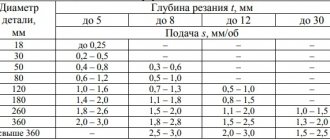
We will present tabular data that displays the main parameters depending on the actions:
| Type of work and material | Cutter diameter, mm | Speed, rpm |
| Cutting/sampling acrylic, composite or PVC up to 10 mm | 3,175 | 18000 |
| Cutting/patterning wood or materials from wood components | From 3.175 to 8 | From 24000 to 15000 |
| Milling brass and bronze | 2 | 15000 |
| Duralumin milling | 3,175 | 15000 – 20000 |
Machining special grooves with end mills
These include T-slots and dovetail slots. Their milling is usually performed on vertical milling machines.
Milling T-slots
Milling simple T-slots involves 2 steps.
- A rectangular slot is produced using a cylindrical end mill.
- Using a T-shaped cutter, a T-shaped groove is made.
If it is necessary to obtain a groove with rolled edges, make a third transition. The chamfers are removed using an angle cutter.
Image #19: three stages of milling a T-slot with rolled edges
Milling a dovetail groove
It also happens in 2 stages.
- A rectangular slot is produced using a cylindrical end mill.
- The operation is completed using a dovetail cutter.
Image #20: Milling a dovetail groove
Range of spindle speeds
Beyond the maximum values of machine spindle rotation speeds, its regulation range is determined. The machine uses a two-speed electric motor. In this case, it is considered as an electrical group with the number of gears and characteristic
The electric motor acts as the first surmountable group.
Intermediate values of spindle speeds are arranged according to the law of geometric progression with the denominator:
where is the number of degrees of regulation of spindle rotation speeds, .
The denominator value obtained from this formula is rounded to the nearest value, which is provided for by the machine tool building standard НІІ-І: 1.06; 1.12; 1.26; 1.41; 1.58; 1.78; 2.0. For our case we accept .
From the normal НІІ-І we write out 21 values of spindle rotation speeds, taking as the largest the closest standard value, which is typical for such a machine - 2500 rpm: 2500; 2000; 1600; 1250; 1000; 800; 630; 500; 400; 315; 250; 200; 160; 125; 100; 80; 63; 50; 40; 31.5; 25.
