Machining metal and other surfaces using a lathe has become an integral part of everyday life in the industry. Many technologies have changed, some have become simpler, but the essence remains the same - correctly selected cutting modes during turning provide the required result. The process includes several components:
- power;
- rotation frequency;
- speed;
- processing depth.
Key manufacturing points
There are a number of tricks that must be followed while working on a lathe:
- fixing the workpiece into the spindle;
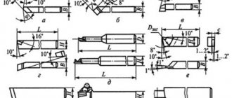
- turning using a cutter of the required shape and size. The material for metal-cutting bases is steel or other carbide edges;
- Removal of unnecessary balls occurs due to different rotation speeds of the caliper cutters and the workpiece itself. In other words, a speed imbalance is created between the cutting surfaces. Surface hardness plays a secondary role;
- the use of one of several technologies: longitudinal, transverse, a combination of both, the use of one of them.
Areas of use
Steel grade 40X is the main material for the manufacture of high-strength parts used in mechanical, instrument and machine tool manufacturing. Most often, it is used to produce solid parts and rotating parts of various mechanisms:
- crank and cam shafts;
- gear;
- cutters for lathes;
- plungers;
- axles and semi-axles;
- rods;
- spindles;
- ring gears;
- bushings;
- slats;
- mandrels
Also, this grade of steel is used for the manufacture of other parts used in difficult conditions, for example at low temperatures. Without it, it is impossible to imagine the production of bolts and other fasteners intended for installation in the construction of road and railway bridges.
Types of lathes
For each specific part, one or another unit is used:
- screw-cutting and turning: a group of machines that are in greatest demand in the manufacture of cylindrical parts from ferrous and non-ferrous metals;
- rotary-turning: types of units used for turning parts. Especially large diameters from metal blanks;
- lobe lathe: allows you to turn parts of cylindrical and conical shapes with non-standard dimensions of the workpiece;
- turret-turning group: production of a part, the workpiece of which is presented in the form of a calibrated pond;
- CNC - numerical control: a new type of equipment that allows you to process various materials with maximum precision. Experts can achieve this using computer adjustment of technical parameters. Turning occurs with an accuracy of micron fractions of a millimeter, which cannot be seen or verified with the naked eye.
Selection of cutting modes
Aluminum turning: problems and their solutions
Aluminum is a fairly malleable material in terms of processing.
It can be sharpened at high speed. However, there are also peculiarities in cutting. With aluminum there are two key problems that can be encountered during processing. This is a high viscosity of the material, as well as a tendency to stick. These features must be taken into account when choosing a processing tool and cutting modes.
Let's start with the increased viscosity of the metal
. Pure aluminum and soft wrought aluminum alloys during processing form very long chips, which tend to wrap around the tool and clog the chip flutes. This often leads to the instrument overheating or breaking.
This feature forces us to take special measures to eliminate negative consequences. In particular, the cutting edges on the inserts must be as sharp as possible. For better chip removal, it is necessary to use coolant.
If aluminum contains a large admixture of silicon (over 13%), then you will not have any problems with eliminating chips - they are much shorter and can be easily removed. However, for turning high-strength aluminum alloys, it is preferable to use diamond-coated inserts.
The second feature that must be taken into account when cutting aluminum is its tendency to stick.
on the cutting edge of the tool. The edge becomes dull, causing increased stress on the tool. As a consequence, poor processing quality, the formation of build-up on the tool and in the cutting zone, an increase in temperature, leading to overheating and jamming of the tool.
Negative consequences can be avoided by installing a more productive operating mode, because low cutting speed only makes the problem worse. It is also necessary to choose the smoothest possible tool designed for turning aluminum and its alloys.
The TIGROTECH company offers the best inserts for processing non-ferrous metals from the American manufacturer Kennametal. Easy choice for various tasks.
The TIGROTECH company openly displays prices and delivery times for SMW-Autoblok driven tools.
You can find them in our catalog in our catalog.
Source
Operating modes
A workpiece made from each specific material requires compliance with the cutting mode during turning. The quality of the final product depends on the correct selection. Each specialized specialist in his work is guided by the following indicators:
- The speed at which the spindle rotates. The main emphasis is on the type of material: rough or finishing. The speed of the first is slightly less than the second. The higher the spindle speed, the lower the cutter feed. Otherwise, melting of the metal is inevitable. In technical terminology, this is called “ignition” of the treated surface.
- Feed – selected in proportion to the spindle speed.
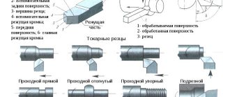
Cutters are selected based on the type of workpiece. Grooving using a turning group is the most common option, despite the presence of other types of more advanced equipment.
This is justified by low cost, high reliability, and long service life.
Changing cutting speed
The cutting speed in metalworking depends on:
- Material, shape, properties of the cutting tool.
- Type of equipment. Lathes, milling machines, etc.
- Workpiece characteristics. For example, steel, what is its tensile strength.
- Cutting depths.
- Type of processing. Turning, thread cutting.
- Reliability and rigidity of workpiece fastening.
- Power and properties of equipment.
- The nature of metalworking.
The cutting speed that is allowed by the cutting element is influenced by various nuances: the durability of the cutter, the physical properties of the workpiece, the quantity and quality of the coolant, the permitted and permissible wear of the cutter.
The higher the speed of movement when cutting, the faster the durability of the cutters decreases. Suitable value for cutting tools from 25 to 55 m/min. If hard alloy plates are installed on the cutters, then this figure can be increased to 75-145 m/min. In this case, their durability will be from half an hour to an hour.
How is speed calculated?
In an engineering environment, the calculation of cutting conditions is calculated using the following formula:
V = π * D * n / 1000,
Where:
V – cutting speed, calculated in meters per minute;
D – diameter of the part or workpiece. Indicators should be converted to millimeters;
n – the value of revolutions per minute of time of the processed material;
π – constant 3.141526 (tabular number).
In other words, the cutting speed is the distance that the workpiece travels in a minute.
For example, with a diameter of 30 mm, the cutting speed will be 94 meters per minute.
If it becomes necessary to calculate the speed, given a certain speed, the following formula is applied:
N = V *1000/ π * D
These values and their interpretation are already known from previous operations.
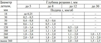
Recommended feeds when processing metals according to the method of V. A. Kolesov (according to Uralmashplant)
Note. Smaller feed values are given for more durable materials, larger ones for less durable ones.
Cutting speed
The cutting speed depends mainly on the material being processed, the material and tool life, cutting depth, feed and cooling.
Based on the experience of high-speed turners at leading factories and laboratory research, special tables have been developed from which you can select the required cutting speed when machining with carbide cutters.
As an example in table. Table 6 shows the recommended cutting speeds for various cutting depths and feeds when longitudinal turning of structural carbon and alloy steels with tensile strength sigmab = 75 kg/mm² using T15K6 carbide cutters.
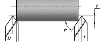
Cutting speeds indicated in table. 6, are designed for certain cutting conditions. They provide for the turning of steels σb = 75 kg/mm² using T15K6 carbide cutters with a leading angle φ = 45° with a cutter life T = 90 min.
Under conditions different from those indicated in table. 6, the tabular data on cutting speed should be multiplied by the corresponding coefficients given below.
Coefficients that take into account the strength of the material being processed: Coefficients that take into account the durability of the cutter: Coefficients that take into account the grade of carbide:
Table 6
Cutting modes when turning structural and alloy steels with tensile strength
σb = 75 kg/mm²
with cutters with T15K6 inserts
Requirements for modern lathes
Lathes designed for high-performance turning are subject to higher demands than conventional lathes.
When working at high cutting speeds, there is a danger of vibrations due to insufficient rigidity of the machines, the presence of excessive clearances in the spindle bearings and in the movable joints of the support, and unbalance of individual rapidly rotating parts of the machine, chuck or workpiece.
Consequently, for quiet, vibration-free operation of the machine, its individual parts (spindle, support, tailstock) must have sufficient rigidity, and the rotating parts must be carefully balanced.
The power of a lathe for high-speed cutting must be greater, since the higher the cutting speed, the greater the electric motor power required.
These requirements are met by machines produced by the domestic machine tool industry, for example, the 1A62 screw-cutting lathe, which we examined in detail, the 1K62 machine, etc.
However, for high-performance cutting, in some cases it is possible to use old-model lathes available in factories, with some modification of their main components.
This kind of alteration of machines is called modernization
.
Conversion of existing machines for high-performance cutting in some cases comes down mainly to increasing the spindle speed and replacing the existing electric motor with a more powerful one; in other cases, more complex alterations are required, for example, it is necessary to change the design of the friction clutch, the main drive, add devices for forced lubrication of the spindle, strengthen individual parts of the machine, etc.
Increasing the spindle speed is one of the widely used measures when converting machine tools to high-speed cutting and is achieved by changing the diameters of existing pulleys. At the same time, the electric motor is also replaced with a more powerful one. The flat-belt transmission from the electric motor to the machine is replaced by a V-belt (see Fig. 2, b). This transmission allows you to obtain the required increased power and a higher gear ratio without changing the width of the pulley.
Machines transferred to high-speed processing must be thoroughly checked and, if necessary, repaired. When repairing, you should pay attention to the headstock bearings, friction clutch, caliper, etc. The spindle bearings must be carefully adjusted, and the gaps in the moving parts of the caliper are eliminated by tightening the wedges. The friction clutch must be checked and, if necessary, strengthened accordingly. The machine should always be well lubricated, especially its gearbox.
Secure installation of the machine on the foundation is a prerequisite for avoiding vibrations, especially for machines with unbalanced rotating parts.
Control questions
1. Explain the procedure for selecting cutting depth and feed. 2. Select the cutting speed when turning structural steel σb = 75 kg/mm² at a depth of cut t - 3 mm with a T15K6 carbide cutter, using the table. 6, taking feed s = 0.2 mm/rev. 3. Select the cutting speed when turning σb = 50-60 kg/mm² at a depth of cut t = 2 mm with a T5K10 carbide cutter at a feed s = 0.25 mm/rev. 4. Select the cutting speed when turning alloy steel σb = 100 kg/mm² at a depth of cut t = 1 mm with a T30K4 carbide cutter at a feed s = 0.15 mm/rev and with a cutter life of 30 minutes. 5. What basic requirements must a high-speed cutting lathe satisfy? 6. What is called machine modernization? 7. List the main ways to modernize existing machines for high-speed cutting.
| Previous page | table of contents | Next page |
Additional materials
During manufacturing, most specialists are guided by the following indicators as an additional guide. Strength coefficient table:
| Workpiece material | Strength limit | Brinell hardness scale | Coefficient, MPa |
| alloy and carbon steel | varies from 400–1100 units | – | 1500–2600 |
| cast iron and also gray | – | 1400–2200 | 1000–1200 |
| bronze | – | – | 600 |
| silumin | – | – | 450 |
| duralumin | tensile strength from 250 to 350, but often higher depending on the quality of the workpiece | – | 600–1100 |
Material strength coefficient:
| Steel, kg/mm | Indicator value |
| 50,1–60,1 | 1,61 |
| 60,1–70,3 | 1,27 |
| 70,3–80,1 | 1,1 |
| 80,3–90,1 | 0,87 |
| 90,3–100,1 | 0,73 |
| Cast iron, kg/mm | Indicator value |
| 140,1–160,3 | 1,50 |
| 160,1–180,1 | 1,21 |
| 180,1–200,3 | 1,1 |
| 200,3–220,3 | 0,83 |
Cutter life coefficient:
| Duration value, minutes | Index |
| 27–30 | 1,27 |
| 43–46 | 1,11 |
| 57–60 | 1,09 |
| 83–90 | 1,03 |
Characteristics of steel 40X
The performance qualities and chemical composition of 40X steel are determined by the official standard GOST 4543-2016, according to which the material marking is deciphered as follows:
- 40 – the number means that the average amount of carbon in the composition is 0.40%. Carbon was established as a marking designation, since it is it that determines the main performance characteristics of the metal.
- X means that the steel contains chromium, which acts as an alloying element. If the letter is not followed by numbers, then this brand contains chromium in an insignificant amount - no more than 1.1%.
In addition to carbon and chromium, the chemical composition also includes other components, but according to GOST of the Russian Federation, they are not indicated in the labeling. Steel from foreign manufacturers may be marked differently, but the basic chemical composition of the 40X grade remains approximately similar and includes the following elements:
| Manganese | Silicon | Copper | Carbon | Sulfur | Phosphorus | Chromium | Iron | Nickel |
| 0,5–0,8% | 0,17–0,37% | up to 0.3% | 0,36–0,44% | up to 0.035% | up to 0.035% | 0,8–1,1% | about 97% | up to 0.3% |