Home > Theory > DIY 220V voltage stabilizer circuit
According to the established standard GOST 29322-2014 (IEC 60038:2009), the line voltage from industrial power supplies is supplied with a frequency of 50±0.2 Hz and 230V±10%. Failure to comply with certain rules for installing electrical installations during installation work during operation causes emergency situations. In these cases, the established network parameters may deviate significantly, which negatively affects the equipment that is used as a load. Old household appliances are especially sensitive to power surges: washing machines, refrigerators, air conditioners, vacuum cleaners and hand-held power tools. To eliminate these negative phenomena, the network voltage is stabilized to 220 volts.
General view of one of the homemade voltage stabilizers
In cases of increased voltage, the windings of electric motors overheat, the commutators quickly wear out, breakdowns of the insulating layer and interturn short circuits in the windings are possible. When the voltage is too low, the engines start jerkily or don’t start at all, which leads to premature wear of the starting equipment elements. Contacts on magnetic starters spark and burn, lighting devices do not operate at full power and glow dimly. The best option to stabilize the voltage parameters in the network without negative consequences is the use of a booster transformer in the power supply circuit, the voltage of the secondary winding of which is added to the network voltage, bringing it closer to the established parameters.
In new types of electronic equipment, televisions, personal computers, video or audio players, switching power supplies are installed; they effectively perform the work of stabilizing elements. The switching power supply is able to maintain normal operation of the equipment at a network voltage ranging from 160 to 230V. This method reliably protects equipment from burnout of individual elements of the input circuit due to overvoltage in the network. To protect outdated types of equipment, separate voltage stabilizers are used through which the devices are connected. Such stabilizers are sold in specialized stores, but if you wish and have certain knowledge and practical skills, you can assemble the simplest circuits yourself. Many hobbyists make their own voltage stabilizer.
How to make transformers T1 and T2?
The first transformer T1 with a power of 3 kW is manufactured using a magnetic core with a cross-sectional area (CSA) of 187 sq. mm. And three wires PEV-2:
- For the first wrapping, the PPS is only 0.003 square meters. mm. Number of turns – 8669;
- For the second and third windings, the PPS is only 0.027 sq. mm. The number of turns is 522 on each.
If you don’t want to wind the wire, then you can purchase two TPK-2-2×12V transformers and connect them in series, as in the figure below.
To make an autotransformer with a second power of 6 kW, you will need a toroidal magnetic core and PEV-2 wire, from which a wrap of 455 turns will be made. And here we need bends (7 pieces):
- Wrapping 1-3 bends from wire with PPS 7 sq. mm;
- Wrapping 4-7 bends from wire with PPS 254 sq. mm.
Taps are made on turns (counting from bottom to top): 203, 232, 266, 305, 348, 398. From the network, voltage should be supplied to turn No. 266.
What to buy?
Buy in an electrical and radio equipment store (designation in brackets in the diagram):
- 7 optocoupler triacs MOC3041 or 3061 (U from 1 to 7);
- 7 simple triacs BTA41-800B (VS from 1 to 7);
- 2 LEDs DF005M or KTs407A (VD 1 and 2);
- 3 resistors SP5-2, 5-3 possible (R 13, 14, 25);
- Current equalizing element KR1158EN6A or B (DA1);
- 2 comparing devices LM339N or K1401CA1 (DA 1 and 2);
- Switch with fuse;
- 4 film or ceramic capacitors (C 4, 6, 7, 8);
- 4 oxide capacitors (C 1, 2, 3, 5);
- 7 resistances to limit the current, at their terminals it should be equal to 16 mA (R from 41 to 47);
- 30 resistances (any) with a tolerance of 5%;
- 7 resistances C2-23 with a tolerance of 1% (R from 16 to 22).
How to make transformers T1 and T2?
The first transformer T1 with a power of 3 kW is manufactured using a magnetic core with a cross-sectional area (CSA) of 187 sq. mm. And three wires PEV-2:
- For the first wrapping, the PPS is only 0.003 square meters. mm. Number of turns – 8669;
- For the second and third windings, the PPS is only 0.027 sq. mm. The number of turns is 522 on each.
If you don’t want to wind the wire, then you can purchase two TPK-2-2×12V transformers and connect them in series, as in the figure below.
To make an autotransformer with a second power of 6 kW, you will need a toroidal magnetic core and PEV-2 wire, from which a wrap of 455 turns will be made. And here we need bends (7 pieces):
- Wrapping 1-3 bends from wire with PPS 7 sq. mm;
- Wrapping 4-7 bends from wire with PPS 254 sq. mm.
Taps are made on turns (counting from bottom to top): 203, 232, 266, 305, 348, 398. From the network, voltage should be supplied to turn No. 266.
Types of stabilizers
All industrial designs of such equipment can be divided into two large groups:
- electromechanical;
- pulsed.
Electromechanical
The operation of electromechanical devices is based on a servo drive, which is capable of changing the number of winding turns (and therefore the output voltage) by moving a conductive slider along a rheostat. Such devices are cheaper than all other models and have very good stabilization performance. However, they are more likely to break due to the presence of many mechanical parts.
But their main disadvantage is the response speed. Due to the fact that the drive does not move the current collector instantly, the stabilization delay can be up to 0.1 seconds, which is catastrophically long for devices that are sensitive to differences. In other words, such a stabilizer may simply not have time to protect modern electronics. In addition, due to the presence of mechanical parts, reproducing such a device at home is a non-trivial task.
Pulse
Stabilizers are called pulse stabilizers, the operation of which is based on the principle of accumulating current and distributing it to the consumer in fragments - pulses. These time intervals allow the system to accumulate the required current in the capacitors, and then provide stabilized power. Such devices also include devices whose operation is based on triacs and thyristors.
Such devices are more expensive than their electromechanical counterparts, but they are also much more reliable - there are no rubbing or moving parts, which means that, in fact, there is nothing to break. True, their stabilization indicators are worse - they are only capable of a proportional increase or decrease in input indicators. But the response speed is up to 20 milliseconds, and this is enough to protect even the most sensitive household electrical appliances. In addition, such a device can be assembled with your own hands, having the necessary skill and element base.
In addition to separation according to the principle of stabilization, there is a separation into single- and three-phase devices. But due to the fact that single-phase power is usually used at home, we do not take three-phase devices into account.
Which is better: relay or triac
If we compare a triac stabilizer and a relay or thyristor stabilizer, then the first one is undoubtedly a more reliable, durable and safe device. This is explained by the absence of switches with moving contacts, the presence of a control board, a powerful autotransformer and power triac switches. The only drawback of triac stabilizers, compared to other devices, is their high cost, which over time justifies itself with a long service life and high reliability.
Thus, the device described in this article allows us to effectively deal with such a problem for many owners of apartments, country houses and country houses as voltage surges in the electrical network. The use of a stabilizer allows you to reduce to zero the risk of breakdown of electrical appliances and subsequent expensive repairs from short-term power surges in the network. The big difference in the price of such devices, compared to analogues, is several times less than the cost of repairing or purchasing new devices and equipment damaged by surges in unstable network electric current.
Necessary measure
Ideally, the electrical network can operate efficiently with minor voltage drops - no more than 10%, both higher and lower than the nominal 220V. However, as real operating conditions show, these changes are sometimes quite significant. And this already threatens the failure of connected devices.
And to avoid such troubles, a device such as a voltage stabilizer was created. And if the current goes beyond the permissible value, the device will automatically de-energize the connected electrical appliances.
What else could cause the need for such a device and why do some people think about making a homemade 220V voltage stabilizer according to the circuit? The presence of such an assistant is justified due to the following possibilities:
- Household appliances are guaranteed to work for a long time.
- Mains voltage monitoring.
- The specified voltage level is maintained automatically.
- Current surges do not affect electrical appliances.
If such electrical “anomalies” happen frequently where you live, you should think about purchasing a good stabilizer. As a last resort, assemble it yourself.
Assembly features of the device for voltage equalization
The current stabilizing device microcircuit is installed on a heat sink, for which an aluminum plate is suitable. Its area should not be less than 15 square meters. cm.
A heat sink with a cooling surface is also necessary for triacs. For all 7 elements, one heat sink with an area of at least 16 square meters is sufficient. dm.
In order for the AC voltage converter we manufacture to work, you will need a microcontroller. The KR1554LP5 microcircuit copes with its role perfectly.
You already know that you can find 9 flashing diodes in the circuit. All of them are located on it so that they fit into the holes that are on the front panel of the device. And if the stabilizer body does not allow their location, as in the diagram, then you can modify it so that the LEDs come out on the side that is convenient for you.
Now you know how to make a 220 volt voltage stabilizer. And if you have already had to do something similar before, then this work will not be difficult for you. As a result, you can save several thousand rubles on the purchase of an industrial stabilizer.
↑ Program
The program is written in SI language (mikroC PRO for PIC), divided into blocks and provided with comments. The program uses direct measurement of alternating voltage by a microcontroller, which simplifies the circuit. The microprocessor is PIC16F676
.
zero
program block waits for the appearance of a falling zero crossing. At this drop, either the alternating voltage value is measured, or the relay begins to switch.
izm_U
program block measures the amplitudes of the negative and positive half-cycles
In the main program, the measurement results are processed and, if necessary, a command is given to switch the relay. For each relay group, separate turn-on and turn-off programs are written, taking into account the required R2on
,
R2off
,
R1on
and
R1off
. The 5th bit of port C is used in the program to send a clock pulse to the oscilloscope so that the results of the experiment can be viewed.
Comments:
Cherevaty
Informative article, thank you. The diagrams are detailed and easy to read. There will be something to do on vacation. I want to throw such a stabilizer under a homemade wind station that powers a light bulb in a gazebo. Do you think the scheme will work?
Gaivoronsky
I assembled everything according to the diagram - everything works, thanks to the author. I will continue to experiment with a soldering iron and printed circuit boards.
Slavon
Uff... Does anyone know where all the parts can be bought? So that in one place you don’t have to overpay for the delivery of one relay, otherwise the stabilizer will turn out to be more expensive than a store-bought one
Alex
Slavon, yes, all these parts are sold on any piece of hardware. Don't bother. In any case, they are cheaper on the market, and you can buy used ones (but only if they are Soviet) - so in general the price turns out to be a pittance
Oleg Kyiv
The language of presentation certainly deserves special attention.
Vyacheslav
How were you able to repeat the design if there is no data on the magnetic circuit for the T2 transformer?
Sergey
How to convert the divider to a voltage of 100-250 volts?
↑ Files
Hello, reader! My name is Igor, I'm 45, I'm a Siberian and an avid amateur electronics engineer. I came up with, created and have been maintaining this wonderful site since 2006. For more than 10 years, our magazine has existed only at my expense.
- Thank you for your attention! Igor Kotov, editor-in-chief of Datagor magazine
Ivan Vnukovsky, Ukraine, Dnepropetrovsk
Disadvantages of ET models offered on the market
Cheap models do not have special overload protection.
Despite the economical and well-developed design, electric power supplies have a number of disadvantages, which are usually classified as:
- lack of special overload protection in the simplest Chinese models;
- the resulting need for mandatory modification of the scheme;
- Many market samples do not have an input filter device, which forces them to add a smoothing electrolytic capacitor (it is placed after the “powerful” choke).
The listed disadvantages usually include the “hard” operating mode of high-voltage transistors connected according to a key circuit.
In the event of an accidental output short circuit (SC), these elements simply “burn out,” which leads to the need for an urgent update of the entire electronic module. Often, the rectifier based on semiconductor diodes also breaks down and also needs to be replaced.
Contents
I was interested in this information, I remembered that in the cinema "Ukraine" there was also continuous voltage switching - there, during the switching period, a wirewound resistor was connected between adjacent contacts of the switch. I started looking on the Internet for anything useful about this. I was not able to get acquainted with invention No. 2356082.
I managed to find an article “Types of voltage stabilizers”, which talked about the possibility of connecting a diode to the relay contacts at the moment of switching. The idea is to switch the AC voltage during the positive half-cycle. In this case, you can connect a diode in parallel with the relay contacts for the switching period.
Based on this article, the most common relays were taken and the switch-off time, the time spent in the broken state and the switch-on time were measured. During the measurements, I saw contact bounce on the oscilloscope, which caused a lot of sparking and erosion of the contacts, which sharply reduces the service life of the relay.
To implement and test this idea, a 2 kW AC relay stabilizer was assembled to power the apartment. Auxiliary relays connect the diode only for the duration of the main relay switching during the positive half-cycle. It turned out that the relays have significant delay and bounce times, but, nevertheless, the switching operation was managed to fit into one half-cycle.
Read also: How to crimp an Internet cable by color
Manufacturing stages
To assemble a 220V voltage stabilizer for your home with your own hands, you first need to prepare a printed circuit board measuring 115x90 mm. It is made of foil fiberglass. The layout of the parts can be printed on a laser printer and transferred to the board using an iron.
Let's watch the video, a homemade simple device:
electrical circuit diagram
Next we move on to assembling the transformers. For one such element you will need:
- magnetic core with a cross-sectional area of 1.87 cm²;
- three PEV-2 cables.
The first wire is used to create one winding, and its diameter is 0.064 mm. The number of turns should be 8669.
The two remaining wires will be needed to make other windings. They differ from the first one in diameter being 0.185 mm. The number of turns for these windings will be 522.
If you want to simplify your task, you can use two ready-made TPK-2-2 12V transformers. They are connected in series.
In the case of making these parts yourself, after one of them is ready, they move on to creating the second. It will require a toroidal magnetic circuit. For the winding, choose the same PEV-2 as in the first case, only the number of turns will be 455.
Also in the second transformer you will have to make 7 taps. Moreover, for the first three, a wire with a diameter of 3 mm is used, and for the rest, buses with a cross-section of 18 mm² are used. This will help prevent the transformer from heating up during operation.
connection of two transformers
It is better to purchase all other components for a device you create yourself in a store. Once everything you need has been purchased, you can begin assembly. It is best to start by installing a microcircuit that acts as a controller on a heat sink, which is made of aluminum platinum with an area of more than 15 cm². Triacs are also mounted on it. Moreover, the heat sink on which they are supposed to be installed must have a cooling surface.
Next you need to install LEDs on the board. Moreover, it is better to choose blinking ones. If it is not possible to arrange them according to the diagram, then you can place them on the side where the printed conductors are located.
If assembling a 220V triac voltage stabilizer with your own hands seems complicated to you, then you can opt for a simpler linear model. It will have similar properties.
The effectiveness of a handmade product
What pushes a person to make this or that device? Most often - its high cost. And in this sense, a voltage stabilizer assembled with your own hands is, of course, superior to a factory model.
In addition, all the parts for such a device were previously purchased in the store, so if they fail, you can always find a similar one.
If we compare the reliability of a stabilizer assembled with our own hands and manufactured at an enterprise, then the advantage is on the side of factory models. At home, it is almost impossible to develop a model with high performance, since there is no special measuring equipment.
Conclusion
There are different types of voltage stabilizers, and some of them are quite possible to make with your own hands. But to do this, you will have to understand the nuances of the operation of the equipment, purchase the necessary components and carry out their proper installation. If you are not confident in your abilities, then the best option is to purchase a factory-made device. Such a stabilizer costs more, but the quality is significantly superior to models assembled independently.
DIY adjustable power supply
A power supply is a necessary thing for every radio amateur, because to power electronic homemade products you need a regulated power source with a stabilized output voltage from 1.2 to 30 volts and a current of up to 10A, as well as built-in short circuit protection. The circuit shown in this figure is built from the minimum number of available and inexpensive parts.
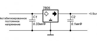
Scheme of an regulated power supply on an LM317 stabilizer with short-circuit protection
The LM317 IC is an adjustable voltage regulator with built-in short circuit protection. The LM317 voltage stabilizer is designed for a current of no more than 1.5A, so a powerful MJE13009 transistor is added to the circuit, capable of passing through itself a really high current of up to 10A, according to the datasheet, a maximum of 12A. When you rotate the knob of the variable resistor P1 by 5K, the voltage at the output of the power supply changes.
There are also two shunt resistors R1 and R2 with a resistance of 200 Ohms, through which the microcircuit determines the output voltage and compares it with the input voltage. 10K resistor R3 discharges capacitor C1 after the power supply is turned off. The circuit is powered by voltage from 12 to 35 volts. The current strength will depend on the power of the transformer or switching power supply.
I drew this diagram at the request of novice radio amateurs who assemble circuits using wall-mounted installations.
Scheme of an regulated power supply with short-circuit protection on LM317
It is advisable to carry out the assembly on a printed circuit board, so it will be beautiful and neat.
Printed circuit board of the regulated power supply on the LM317 voltage regulator
The printed circuit board is made for imported transistors, so if you need to install a Soviet one, the transistor will have to be unfolded and connected with wires. The MJE13009 transistor can be replaced with the MJE13007 from the Soviet KT805, KT808, KT819 and other npn structure transistors, it all depends on the current you need. It is advisable to reinforce the power paths of the printed circuit board with solder or thin copper wire. The LM317 voltage stabilizer and the transistor must be installed on a radiator with sufficient area for cooling; a good option is, of course, a radiator from a computer processor.
It is advisable to screw a diode bridge there. Don't forget to insulate the LM317 from the heatsink with a plastic washer and a heat conductive gasket, otherwise there will be a big boom. Almost any diode bridge can be installed with a current of at least 10A. Personally, I installed the GBJ2510 at 25A with double the power reserve, it will be twice as cool and reliable.
And now the most interesting part... Testing the power supply for strength.
I connected the voltage regulator to a power source with a voltage of 32 volts and an output current of 10A. Without load, the voltage drop at the output of the regulator is only 3V. Then I connected two series-connected halogen lamps H4 55 W 12V, the lamp filaments were connected together to create a maximum load, the result was 220 W. The voltage dropped by 7V, the nominal voltage of the power supply was 32V. The current consumed by four halogen lamp filaments was 9A.
The radiator began to heat up quickly, after 5 minutes the temperature rose to 65C°. Therefore, when removing heavy loads, I recommend installing a fan. You can connect it according to this diagram. You can not install the diode bridge and capacitor, but connect the L7812CV voltage stabilizer directly to capacitor C1 of the regulated power supply.
Connection diagram of the fan to the power supply
What happens to the power supply if there is a short circuit?
In the event of a short circuit, the voltage at the output of the regulator is reduced to 1 volt, and the current is equal to the current of the power source, in my case 10A. In this state, with good cooling, the unit can remain for a long time; after the short circuit is eliminated, the voltage is automatically restored to the limit set by the variable resistor P1. During the 10-minute short-circuit test, no parts of the power supply were damaged.
Radio components for assembling an adjustable power supply on LM317
- Voltage stabilizer LM317
- Diode bridge GBJ2501, 2502, 2504, 2506, 2508, 2510 and other similar ones designed for a current of at least 10A
- Capacitor C1 4700mf 50V
- Resistors R1, R2 200 Ohm, R3 10K all resistors with a power of 0.25 W
- Variable resistor P1 5K
- Transistor MJE13007, MJE13009, KT805, KT808, KT819 and other npn structures
Friends, I wish you good luck and good mood! See you in new articles!
I recommend watching a video on how to make an adjustable power supply with your own hands
Connection errors
1
You may have everything connected perfectly and the diagram followed, but the stabilizer will constantly heat up and turn off, or errors will appear on its display.
Read in detail about where you can and where you should never place this device in the article “Where to install a voltage stabilizer in the house.”
2
Of course, this point can hardly be called a mistake. Moreover, 90% of consumers do just that.
However, this switch can really save your device from failure.
First you turn off the machines on the stabilizer panel.
Then move the switch itself to the TRANSIT or BYPASS position.
And only then turn on the machines again.
Many people forget about this and switch under load. Which ultimately leads to breakdowns.
With a 3-position automatic machine this is impossible. You automatically switch the voltage, without any manipulation on the stabilizer. And all this with one key!
There is no need to remember any sequence. So this procedure can be safely trusted to any family member.
3
You can choose a smaller cross-section only when powering individual electrical receivers.
If your whole house is sitting on a stabilizer, then please follow the input parameters according to the entire general house load.
4
For some reason, many people forget that often the entire load of your home passes through the stabilizer. Exactly the same as on the automatic input.
At the same time, in the electrical panel all the wires are crimped, even on light switches with minimal currents, but on the terminal blocks of the stabilizer or its circuit breakers, you can always find a bare wire simply pressed in with a screw.
Therefore, do not skimp and purchase the appropriate tips along with the device in advance.
5
Sometimes after connecting the stabilizer, the input machine starts to knock out. In this case, without a stabilizer, everything is fine and nothing is turned off.
Many people immediately blame it on an incorrect connection diagram or a defect in the device. They take it for warranty repairs, etc.
But the reason may be completely different. If your voltage is too low, 150-160V, then when you increase it to the standard 220-230V, the current in the network will increase significantly.
Hence all the problems
Please pay attention to this before you take it back to the store.
Sources - https://cable.ru, Kabel.RF
Servo motor repair
When the engine itself burns out, there are two options:
- Buying a new one and installing it.
- An attempt to restore an old engine.
The second option makes it possible to revive the engine on your own, however, not for a long time. For resuscitation, you need to disconnect the engine from the general circuit. After this, it must be connected to a powerful power source.
Your task is to supply current to its outputs with a constant voltage of 5 volts. The current should be between 90 and 160 mA. When such a current is supplied, every small particle of “garbage” burns out on the motor brushes.
Helpful advice: since the motor is of a reversible type, the polarity must be changed when applying voltage. This procedure is carried out twice.
After such actions, the engine will be able to work again, and the stabilizer will perform its main function. Next, according to a simple diagram, you can carry out the procedure for connecting the voltage stabilizer released.
This circuit involves connecting the input phase and neutral cables to the input phase and neutral terminals, respectively. The connection of the output wires is similar. A grounding wire must also be connected.
Determining the type of protection
Today, stabilizers are divided into 2 main types:
- stationary devices for voltage stabilization, their installation is done for the whole house;
- portable models, they can stabilize the operation of just a few electrical devices.
Also, stabilizers for stationary use are divided into single-phase and three-phase, it all depends on the conditions in which they are planned to be used. In your house or apartment, it would be more appropriate to install and connect a stabilizer near the electricity distribution board; with this step you can prevent failures and overloads of the entire network.
Choosing a voltage stabilizer for a computer
A computer consists of a system unit and a monitor. Therefore, the power must be summed up. Also, if the stabilizer also includes additional devices (scanner, printer, etc.), then all the power must be summed up and the resulting result compared with the range of ratings of the voltage stabilizers in question. As a rule, for a home computer you can choose a stabilizer with a power of no more than 1000 W.
For a computer, I also recommend using Smart UPS (interactive UPS) instead of a stabilizer. They contain a stabilization function (relay type) and have a battery. Thus, the voltage will be relatively stable and the reserve will be ensured.
Principle of operation
Such a stabilizing device works as follows:
- The voltage supplied to the device from the external network is measured by the control board (controller) using a special sensor;
- Based on the measurements obtained, the controller makes a decision to adjust the voltage;
- The controller sends the corresponding signal to the input triacs;
- Using the signal sent to the triacs by the controller, a voltage equalized to a certain value is supplied;
- Using an autotransformer located in the housing, the voltage supplied from the external network is equalized to the value necessary for the normal operation of electrical appliances.
This multi-step process takes a fraction of seconds. At the same time, unlike relay models, the presence of triacs makes it possible to turn on and off the transformer windings silently and very quickly.
Advantages and disadvantages
The advantages of such a device include:
- High performance - the device, thanks to the presence of high-speed switching simulators, is able to respond very quickly to voltage surges in the network, smoothing them out to the required value;
- Wide range of input voltage - stabilizers of this type are capable of operating at input voltage values from 95 to 275 V (for a single-phase model), from 260 to 470-471 V (for three-phase stabilizers);
- High accuracy of stabilization - the output voltage produced by such devices has a maximum fluctuation within 1.5% (3.3-5.7 V), which does not have a negative impact on the operation of the devices connected to it.
- Monitoring the values of the input and output potential difference with an error of no more than 0.5%;
- High efficiency - thanks to the use of a triac, the value of this indicator for most models reaches 95-97%;
- Silence – the absence of relay switches and moving contacts in the design of the stabilizer allows it to operate almost silently;
- Small dimensions - stabilizers assembled on triacs, compared to relay ones, are small in size and can be compactly placed on the floor or wall of even the smallest room;
- Long service life - most modern high-quality models can normally perform their functions for 10 years or more;
- High power - various models are capable of ensuring normal operation of connected devices and equipment with a total power of 3 to 10 kW.
The disadvantages of such stabilizers include:
- High cost - high-quality models of stabilizers have a fairly high cost, which is not always affordable for many owners of apartments and houses.
- An abrupt change in the potential difference at the output of the device - this drawback is typical for inexpensive Chinese-made models. It practically does not appear in more expensive analogues.
On a note. Despite the high cost of such devices, their purchase in case of problems with the network voltage will be very profitable and will pay for itself quite quickly - if the stabilizer is missing, serious breakdowns of sensitive household appliances, pumping and heating equipment can occur. In some cases, such surges not only damage devices connected to the network, but also render them inoperable, which requires their replacement, leading to unplanned and significant financial expenses and other inconveniences.
Advantages of a household rectifier
By design and principle of operation, a double conversion stabilizer has a number of positive properties. A household inverter has the following qualities that affect the performance of the device:
- Extended input voltage indicator in the range of 115−300.
- Stabilization of the output voltage up to 220 V in case of a sharp current surge.
- Low noise threshold during operation of the device.
- Compact body dimensions and low weight.
- Filtering of high-frequency interference and emissions.
- Efficiency > 90%.
- Low accuracy of input voltage normalization.
- Operational regulation of electric current strength.
- Unpretentiousness to maintenance and operating conditions.
Additional functions of voltage stabilizers
In addition to the main function of voltage stabilizers - stabilization, there is also the following minimum set of functions and parameters:
Maybe this will be interesting too?
- Output voltage analysis. The stabilizer must be equipped with an information (digital or pointer) display that shows the output voltage. If the stabilizer has an input voltage analysis function, this will be additional useful information.
- At higher ratings (usually from 3000 VA), the “Bypass” function is installed - a function in an electronic device (signal processing, voltage stabilization, etc.) that allows you to switch the input signal directly to the output, bypassing all functional blocks. That is, the ability to turn on the network bypassing the voltage stabilizer. If the voltage has returned to normal or you do not need a stabilizer now, press the lever up and the voltage goes bypassing the stabilization blocks.
- Types of fastening of voltage stabilizers There are two types of fastening of voltage stabilizers - floor and wall versions. Floor-standing design means that the stabilizer is located on the floor or shelf. This arrangement is not always convenient, because especially large denominations cannot be placed on a shelf due to their weight, and they occupy quite large areas on the floor. When mounted, the stabilizers are made flatter for the convenience of customers. In principle, they can also be used in a floor-standing version, only often the information part of the display is in this case “upside down” towards the user.
- Many models on the voltage stabilizer market use a delay button. This is done so that if the voltage in the network disappears or temporarily goes beyond the operating range, the equipment will come to a rest position during this delay time before the next turn on. In many stabilizers, the delay button is offered in several ranges -6, 90, 120 sec. In more modern models, the delay has already become automatic and when it is turned on, it shows the consumer on the display the time the stabilizer is turned on in the form of a countdown.
Relay damage
If at the stage of diagnosing the voltage stabilizer a faulty relay was identified, then the best thing that can be done is to replace it with a new one. This will be much more reliable. However, if a decision is made to repair the relay, then this should be done according to the following algorithm:
You need to test the relay coil with a multimeter. If it is broken, then it needs to be rewinded (here again you need an electric winder). If the coil is working properly, then the relay should be disassembled
This must be done extremely carefully so as not to damage its contents. When the device is disassembled, the contacts are inspected for melting, burning or darkening. If there are any, they should be removed with a needle file or a thin nail file. Anything will do, just to remove carbon deposits and unevenness. Voltage is then applied to the relay coil to ensure that its normally open contacts move and connect.
Reliability of operation must be checked with an ohmmeter. The contact resistance should be close to zero. Afterwards the relay is assembled. If possible, it is tested under load for a couple of hours and, if the tests are successfully completed, it is returned.
Anything will do to remove carbon deposits and unevenness. Voltage is then applied to the relay coil to ensure that its normally open contacts move and connect. Reliability of operation must be checked with an ohmmeter. The contact resistance should be close to zero. Afterwards the relay is assembled. If possible, it is tested under load for a couple of hours and, if the tests are successfully completed, it is returned.
Assembly features of the device for voltage equalization
The current stabilizing device microcircuit is installed on a heat sink, for which an aluminum plate is suitable. Its area should not be less than 15 square meters. cm.
A heat sink with a cooling surface is also necessary for triacs. For all 7 elements, one heat sink with an area of at least 16 square meters is sufficient. dm.
In order for the AC voltage converter we manufacture to work, you will need a microcontroller. The KR1554LP5 microcircuit copes with its role perfectly.
You already know that you can find 9 flashing diodes in the circuit. All of them are located on it so that they fit into the holes that are on the front panel of the device. And if the stabilizer body does not allow their location, as in the diagram, then you can modify it so that the LEDs come out on the side that is convenient for you.
Now you know how to make a 220 volt voltage stabilizer. And if you have already had to do something similar before, then this work will not be difficult for you. As a result, you can save several thousand rubles on the purchase of an industrial stabilizer.
Subtleties of adjustment
The need for a voltage regulator will be in the following conditions:
- Adjustment of alternating and direct voltage is necessary.
- Ability to regulate load voltage.
Each listed item defines its own set of radio components in the circuit. But the device of the simplest regulator is based on a variable resistor. When adjusting AC voltage, no distortion is created. With the help of variable resistance it is possible to regulate direct current.
To ensure that the voltage and current load are of a given parameter, stabilizers are used. The output voltage is checked to the correct value, and if small specified changes occur, the regulator automatically resets.
You can find many step-by-step instructions on how to make a voltage regulator. But the simplest and most understandable option is considered to be a device based on integrated circuits. The convenience of the products allows you to power LEDs and other lighting systems in the car. The network regulator requires a step-down converter, and a rectifier should be connected to the input.
Very often the load can have different parameters, so for such cases it is impossible to do without special voltage stabilizers. Their work can be carried out in several modes.
For all electronic devices, it is important to obtain a stable voltage. They have non-linear components built into the electrical circuit.
There is a voltage regulator based on a thyristor. This is a very powerful semiconductor, which is used in high-power converter devices. Thanks to its specific control, it is used for “recess” switching.
Operation of the Suntek electromechanical stabilizer
To change the input voltage, an autotransformer is used, which can change the voltage within the required limits. In this case, the voltage at the output of the stabilizer does not go beyond the operating range.
In rural areas, for the safe use of household appliances, a single-phase 220V voltage stabilizer is required, which, in the event of a strong voltage drop in the network, maintains a rated output voltage of 220 volts at the output.
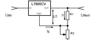
The electrical design has three threshold blocks, built on the principle of a voltage divider, consisting of resistances (R2-VD1-R1, VD5-R3-R6, R5-VD6-R6). In addition, the circuit uses two transistor switches VT1 and VT2 that control relays K1 and K2.
Diodes VD2 and VD3, together with filter capacitance C2, constitute the power source for the entire device. Capacitors C1 and C3 are used to absorb small voltage sags in the AC network. Capacitance C4 and resistor R4 are spark arresting components. To reduce self-induction voltage surges, two semiconductor diodes VD4 and VD7 are introduced into the circuit in the relay windings.
If the network voltage drops below 185 volts, then the relay contacts are turned on as in the diagram. The load voltage will be the sum of the mains voltage plus the voltage boost received from windings II and III of transformer T1.
If the voltage is in the range of 185-205 volts, then the zener diode VD5 is open. Current flows through relay K1, VD5 and resistors R3 and R6. But this current is not enough to trigger relay K1. Due to the voltage drop across resistor R6, VT2 opens. This transistor triggers relay K2 which, with its contacts, switches winding II (voltage booster).
If the network voltage is normal 205-225 volts, then the zener diode VD3 is open. This leads to the opening of VT1, so the second threshold block and VT2 are turned off along with relay K2. But K1 is triggered and with its contacts turns off windings II and III, and therefore the output voltage corresponds to the input.
When the mains voltage level increases above 225 but below 245 volts, the zener diode VD6 opens, opening both. Both relays are activated by winding III T1, connected in antiphase with the mains voltage (i.e. subtracted)). The output will have a normal alternating voltage in the range of 205-225 volts.
Inverter technology
A distinctive feature of such devices is the absence of a transformer in the design of the device. However, voltage regulation is carried out electronically, and therefore it belongs to the previous type, but is, as it were, a separate class.
If you want to make a homemade 220V voltage stabilizer, the circuit of which is not difficult to obtain, then it is better to choose inverter technology. After all, the principle of operation itself is interesting here. Inverter stabilizers are equipped with double filters, which allows minimizing voltage deviations from the nominal value within 0.5%. The current entering the device is converted into direct voltage, passes through the entire device, and before exiting it again takes on its previous form.
Homemade apparatus
A high-quality stabilizer for several kW and an output current of more than 10 amperes can be assembled based on an old transformer installed in a welding machine. However, such a “blank” is not easy to find. Moreover, the current technology is suitable for subsequent use for its intended purpose. For reproduction at home without professional skills, the circuit presented below on electronic components is suitable. It will provide:
- prompt correction of output parameters with a switching speed of no more than 8-12 milliseconds;
- operating input voltage range 125-265 V;
- power of connected consumers up to 5.5 kW.
Electrical and wiring diagram, printed circuit board
Advantages of a homemade device
In addition to good technical parameters, the following advantages should be noted:
- reasonable costs;
- the ability to independently perform repair operations.
Flaws
The consumer parameters of the product largely depend on the assembly. In this case, it is assumed that there are no well-developed skills and professional installation (measuring) equipment. On the other hand, careful execution of individual work operations will help control quality more thoroughly than the actions of third-party contractors.
Differences from factory models
Modern production is characterized by a high level of automation. This reduces the harmful influence of the “human factor” and reduces costs. With the use of professional technologies it is easier to ensure a perfect appearance. However, when creating a homemade product, you can use unique technical and aesthetic solutions.
Accessories
Main components (functional components):
- transformer power supply with diode temperature compensation and comparator;
- rectifier with divider;
- transistor load connection delay circuit;
- controller on digital chips;
- LED indication of operating modes and emergency situations;
- keys from optitron pairs.
Features of home production
Standard transformers TPK-2-2x12V are suitable. If necessary, you can create analogs with your own hands, using PEVs with a conductor diameter of 0.064 mm (8669 turns) and 0.185 mm (522 turns) in the primary and secondary windings, respectively.
Design characteristics
Compared to analogues, stabilizers of this type have the following design features:
- High-speed semiconductor parts such as triacs are used as power switches in this device;
- To obtain a stable output potential difference, stabilizers of this type use a built-in autotransformer with windings connected in series;
- The operation of the device is controlled by an electronic controller - a special board with a microcircuit placed on it.
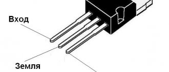
Triac
Principle of operation
How does our network voltage stabilizer, which is easy to make with your own hands, work?
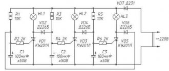
After the power is turned on, capacitor C1 is in a discharged state, transistor VT2 is open, and VT2 is closed. Transistor VT3 is also closed. It is through it that current will be supplied to each LED and triac optotron.
Since this transistor is off, the LEDs are not lit, each triac is off, and the load is off. At this time, electric current passes through resistor R1 and enters C1. Next, this capacitor is charged.
The delay interval lasts only three seconds. During this time, all transient processes are carried out, and after completion, the Schmitt trigger is triggered, the basis of which is transistors VT1 and VT2.
Next, the third transistor opens and the load is turned on.
The voltage that comes out from the third winding T1 is rectified by the diode VD2 and capacitor C2. Next, the current passes through the divider R13…14. From R14, a voltage whose level is proportional to the number of volts in the network is included in each non-inverting input of the comparators.
The number of comparators is eight and they are all located on chips DA2 and DA3. At the same moment, a constant reference current enters the inverting input of each comparator. It is supplied by resistor dividers R15…23.
After this, the controller comes into play, which processes the signal at the input of each comparator.