Devices that are included in the power supply circuit and maintain a stable output voltage are called voltage stabilizers. These devices are designed for fixed output voltages: 5, 9 or 12 volts. But there are devices with adjustment. They can be set to the desired voltage within certain accessible limits.
Most stabilizers are designed for a certain maximum current that they can withstand. If you exceed this value, the stabilizer will fail. Innovative stabilizers are equipped with a current blocking, which ensures that the device is turned off when the maximum current in the load is reached and are protected from overheating. Along with stabilizers that maintain a positive voltage value, there are also devices that operate with negative voltage. They are used in bipolar power supplies.
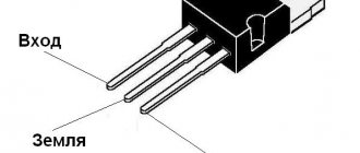
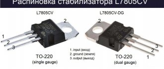
The 7805 regulator is manufactured in a transistor-like package. Three conclusions are visible in the figure. It is designed for a voltage of 5 volts and a current of 1 ampere. There is a hole in the case for fixing the stabilizer to the radiator. The 7805 is a positive voltage device.
The mirror image of this regulator is its 7905 negative voltage counterpart. There will be a positive voltage on the case, a negative value will be sent to the input. -5 V is removed from the output. In order for the stabilizers to work in normal mode, 10 volts must be supplied to the input.
Technical characteristics of the stabilizer LM338:
- Providing output voltage from 1.2 to 32 V.
- Load current up to 5 A.
- Availability of protection against possible short circuit.
- Reliable protection of the microcircuit from overheating.
- Output voltage error 0.1%.
The LM338 integrated circuit is available in two housing options: a metal TO-3 housing and a plastic TO-220 housing:
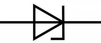
Integral stabilizer and zener diode
Build a stable source of non-standard voltage using three-terminal voltage stabilizers. Schemes to the studio!
What do we see as a result? We see a voltage stabilizer and a zener diode connected to the middle terminal of the stabilizer. XX are the last two digits written on the stabilizer. There may be numbers 05, 09, 12, 15, 18, 24. There may already be even more than 24. I don’t know, I won’t lie. These last two digits tell us the voltage that the stabilizer will produce according to the classic connection scheme:
Here, the 7805 stabilizer gives us 5 Volts at the output according to this scheme. 7812 will produce 12 Volts, 7815 - 15 Volts. You can read more about stabilizers here.
U of the zener diode is the stabilization voltage on the zener diode. If we take a zener diode with a stabilization voltage of 3 Volts and a voltage regulator 7805, then the output will be 8 Volts. 8 Volts is already a non-standard voltage range ;-). It turns out that by choosing the right stabilizer and the right zener diode, you can easily get a very stable voltage from a non-standard range of voltages ;-).
Let's look at all this with an example. Since I simply measure the voltage at the terminals of the stabilizer, I do not use capacitors. If I were powering the load, then I would also use capacitors. Our guinea pig is the 7805 stabilizer. We supply 9 Volts from the bulldozer to the input of this stabilizer:
Therefore, the output will be 5 Volts, after all, the stabilizer is 7805.
Now we take a zener diode at Ustabilization = 2.4 Volts and insert it according to this circuit, it is possible without capacitors, after all, we are just measuring the voltage.
Oops, 7.3 Volts! 5+2.4 Volts. Works! Since my zener diodes are not high-precision (precision), the voltage of the zener diode may differ slightly from the nameplate (voltage declared by the manufacturer). Well, I think it's no problem. 0.1 Volt will not make a difference for us. As I already said, in this way you can select any value out of the ordinary.
Examples of application of the LM338 stabilizer (connection circuits)
The following examples will show you some very interesting and useful power circuits built using the LM338.
Simple regulated power supply on LM338
This diagram is a typical LM338 harness connection. The power supply circuit provides an adjustable output voltage from 1.25 to the maximum supplied input voltage, which should not exceed 35 volts.
Variable resistor R1 is used to smoothly regulate the output voltage.
Simple 5 Amp Regulated Power Supply
This circuit produces an output voltage that can be equal to the input voltage, but the current varies well and cannot exceed 5 amperes. Resistor R1 is precisely selected to maintain a safe 5 amp limiting current limit that can be drawn from the circuit.
Regulated 15 amp power supply
As mentioned earlier, the LM338 microcircuit alone can handle only 5A maximum, however, if it is necessary to obtain a higher output current, in the region of 15 amperes, then the connection diagram can be modified as follows:
In this case, three LM338 are used to provide high current load with the ability to regulate the output voltage.
Variable resistor R8 is designed for smooth adjustment of the output voltage
Digitally controlled power supply
In the previous power supply circuit, a variable resistor was used to regulate the voltage. The circuit below allows you to obtain the required output voltage levels using a digital signal supplied to the bases of the transistors.
Stabilizers for powering microcircuits
Let's consider methods for connecting digital devices made independently using microcontrollers to power. Any electronic device requires a proper power connection to function properly. The power supply is designed for a certain power. A capacitor of significant capacity is installed at its output to equalize voltage pulses.
Power supplies without stabilization, used for routers, cell phones and other equipment, are not directly combined with power supply to microcontrollers. The output voltage of these blocks varies and depends on the connected power. An exception to this rule are chargers for smartphones with a USB port that outputs 5 V.
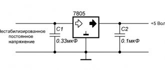
Scheme of operation of the stabilizer, compatible with all microcircuits of this type:
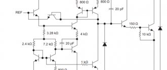
If you disassemble the stabilizer and look at its insides, the diagram would look like this:
For electronic devices that are not sensitive to voltage accuracy, such a device is suitable. But for accurate equipment you need a high-quality circuit. In our case, the 7805 stabilizer produces a voltage in the range of 4.75-5.25 V, but the current load should not be more than 1 A. The unstable input voltage fluctuates in the range of 7.5-20 V. In this case, the output value will always be equal to 5 B. This is an advantage of stabilizers.
When the load that the microcircuit can deliver increases (up to 15 W), it is better to provide the device with cooling by a fan with an installed radiator.
Efficient stabilizer circuit:
Technical data:
- Maximum current 1.5 A.
- Input voltage range – up to 40 volts.
- Output – 5 V.
To avoid overheating of the stabilizer, it is necessary to maintain the lowest input voltage of the microcircuit. In our case, the input voltage is 7 volts.
The microcircuit dissipates the excess power onto itself. The higher the input voltage on the chip, the higher the power consumption, which is converted into heating the case. As a result, the microcircuit will overheat and the protection will trip and the device will turn off.
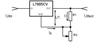
Current source output current on L78
A small nuisance is the quiescent current Id, which adds up to the output current. The quiescent current value is indicated in the datasheet. For most stabilizers Id = 8mA. This figure shows the lowest output current. Those. It will not be possible to obtain a current source with a current value of less than 8 mA.
Ideally, currents from 8 mA to 1 A can be squeezed out of the stabilizer. However, for currents greater than 200-300 mA, a radiator is highly desirable. In principle, it is not advisable to drive currents exceeding 700-800 mA. The 1A indicated in the datasheet is the peak value; in reality, the stabilizer will most likely overheat. Based on the above, we can conclude that the range of output currents is 10-700 mA.
Load resistance
At the same time, it is worth considering the load resistance. For example, if you need to provide 100 mA through a load with a resistance of 100 Ohms, then according to Ohm's law we get the voltage
V= I*R = 0.1 * 100 = 10 Volts
With these simple calculations, we obtained the voltage that needs to be applied to a 100 Ohm load in order to provide it with a current of 100 mA. This means that for this task it is rational to install a 7812 or 7815 stabilizer at 12 volts and 15 volts, respectively, in order to have a reserve.
But it will no longer be possible to provide the same current through a 10 kOhm resistor. This requires a voltage of 100 volts, which these microcircuits can no longer do.
Homemade Voltage Regulator
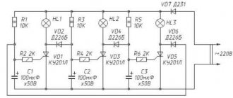
Good day to all! I didn’t think that I would decide to write, but chance forced me to do it... The essence is a homemade regulator! I personally soldered about 10 pieces with a circuit on 3 diode bridges. I installed it on a SUZUKI GSX-R600. The first one was soldered and then contacted the Man from Ukraine, who either came up with this scheme or is his follower on the first line. They rechecked everything and it worked, but it got terribly hot. Or rather, it was noticeably warming up. But it worked. He was outwardly unprepossessing, which I didn’t like. Then I collected more in different variations, but they all worked strangely. Either the voltage was unstable at 14.2, or it generally dropped to 12.5 at higher speeds. I began to decide the decision. Assembled from three parts - bridges, triacs and resistances, control, so that you can find the error and change it, understanding the vibrations of the assembly. It all boiled down to the fact that, with a high degree of probability, the principle of the work depended on the state of the main circuit itself. Whether there is xenon or not, speed, wiring condition - rain, dry, the influence of the motorcycle's electronic systems on the regulator... In the end, it worked, but not correctly. I contacted people who have been doing this for 8-10 years. And not just, but programmed and adapted. In addition, electronics engineers who understand the permissibility of the parameters and speed of operation of the elements, amperage and power... RESULT: I bought a 40 amp rede-regulator from a high-speed motorcycle (BMW S1000RR superbike - standardly installed on DUCATI, KAWASAKI, etc. with a volume of 800-1000 and up to 1400). It cost 2700 rubles. Put. At lower levels it is generally cold, at 4000-5000 rpm, until you can go deaf in the garage, it warms up a little. This is without low beam. Work within 14.2-13.9. At high speeds the readings in the circuit, in the area of the lighting load, increase slightly - up to 14.3-14.4. The neighbor added. The characteristics have not changed. On the battery - 14.06-14.2. Added distant. The voltage just dropped to 12.8 in the circuit (but this is + 2 lamps at 12 V, 55W). It is possible that this relay is a little weak in current strength for my motor, but it works properly and adequately. Everything on the battery is still stable, 13.7-14.2. The battery is new! This is a shunt-type relay-regulator - accepted by the equipment manufacturer as standard (there is also a non-shunt type - more energy-heat adequate)! THINK, CHOOSE! For simple motorcycles (or analog choppers) and scooters without serious electronics, perhaps a homemade relay is relevant, but if you have a SUPER BIKE or SPORT BIKE! Have mercy on your nerves and your faithful friend! This is my advice to you! — A FACT FROM PERSONAL EXPERIENCE!
Answer
