Why are capacitors needed?
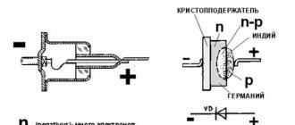
Starting and other types of devices that are connected to engines have an oxide film; it is attached to one of the electrodes. This device has a large capacity even despite its modest dimensions. The device has two conductors with a dielectric between them.
Capacitors are used for single-phase asynchronous motors. Usually they are selected not only to provide starting torque, but also to maintain the required speed. If there is a capacitor on the device circuit, then this provides the following 3 points:
- With a starting element, the state of the electric field will approach circular.
- Magnetic flux indicators will increase, which will have a positive effect on the performance of connected devices.
- The starting torque is easier, so the single-phase electric motor operates stably.
Without a capacitor, the life of the electric motor is reduced, since difficulties during starting wear out the mechanism.
AC brushed motor
Consider a brushed AC motor. Universal commutator motors can be powered from both AC and DC sources. They are often used in power tools, sewing and washing machines, meat grinders - where reverse is needed, adjustment of the rotor speed or its rotation at a frequency of more than 3000 rpm.
The stator and rotor windings of a commutator motor are connected in series. Current is supplied to the rotor windings through brushes in contact with the commutator plates, to which the ends of the rotor windings are connected.
Reversing a single-phase motor with a commutator is carried out by changing the polarity of the stator or rotor windings being connected to the network, and the rotation speed can be adjusted by changing the amount of current in the windings.
The main disadvantages of such an engine:
- high price;
- the complexity of the device, the practical impossibility of repairing it independently;
- significant noise level, difficult to control, creating radio interference.
This is interesting: The principle of operation of a four-stroke engine: we analyze it in detail
Single-phase motor connection diagram
Before connecting the electric motor, it is worth determining that there are two ways to do this: in the form of a star and a triangle. Both options assume that current flows alternately through the wires. This creates a magnetic field that influences the rotor and causes it to move.
When connecting a single-phase motor, no rotating torque appears, so an additional capacitor is used. In this case, the rotation speed does not change, but the power drops. The choice between these schemes depends on the performance of the device used. Connecting a 220 V asynchronous motor is usually done only in a single-phase network; manufacturers even indicate this in their recommendations. In addition to this, they always write the voltage. Motors with a higher rating use a star circuit, while the rest use a delta circuit.
It is easier to connect a capacitor to a single-phase network through a delta circuit, since this way the power of the device almost does not change. Connection losses remain minimal. In the lower image, which was discussed earlier, you can see that there the device is connected only through a star. If the manufacturer indicates this in the technical specifications, then there is no need to be clever. It is easier to accept a change in power than to additionally install three windings and connect them in a triangle.
If a single-phase network is used and a voltage of 220 V is required, then the motor starting circuit is not selected, only a star is used. The power will decrease slightly, but if you select a triangle, the motor will quickly burn out.
Three-phase asynchronous motor: what to pay attention to before connecting it
With a few exceptions, we get the asynchronous machine in an unknown state. Very rarely does it have an inspection certificate and a certified warranty from an electrical laboratory.
Even in this case, I recommend making sure it works personally.
Mechanical condition of the stator and rotor: what can interfere with engine operation
The fixed stator consists of three parts: a middle housing and two side covers, secured with studs. Pay attention to the gap between them and the tightening force with the nuts.
The body must be tightly compressed. A rotor rotates inside it on bearings. Try turning it by hand. Evaluate the force applied: how the bearings work, whether there are any beats.
Without proper experience, minor defects cannot be detected in this way, but a case of severe jamming will immediately appear. Listen to the noises: is there any contact with the stator elements by the rotor when rotating?
After turning the engine to idle and running for a short time, listen again to the sounds of rotating parts.
Ideally, it is better to disassemble the stator, visually assess its condition, wash the dirty rotor bearings and completely replace their lubricant.
Electrical characteristics of stator windings: how to check the assembly circuit
The manufacturer indicates all the main parameters of the electric motor on a special plate attached to the stator housing.
You can trust these factory specifications only if you are sure that after the factory, none of the electricians changed the winding connection diagram or made involuntary mistakes. And I came across such cases.
And the sign itself may become erased or lost over time. Therefore, I propose to understand the technology of rotor spin-up.
To understand the electrical processes occurring inside the motor stator, it is convenient to imagine it in the form of an ordinary toroidal transformer, when three equal windings are symmetrically located on the ring core of the magnetic circuit.
The stator circuit is assembled inside a closed housing, from which only six ends of the windings are removed.
They are marked and connected on a terminal block covered with a lid for assembly according to a star or delta circuit using a standard rearrangement of jumpers.
The right side of the picture shows the assembly of the triangle. I publish the jumper arrangement diagram for the star below.
Electrical methods for checking winding assembly circuits
But not everything is as simple as it might seem at first glance. There are a number of engines that deviate from these rules.
For example, a manufacturer may produce electric motors not for universal use, but for operation in specific conditions with the windings connected in a star configuration.
In this case, he can assemble the three ends of the windings inside the stator housing, and bring out only four wires for connection to the phase and zero potentials.
Installation of these ends is usually performed in the area of the back cover. To switch the windings to a triangle, you will need to open the housing and make additional conclusions.
It's not a difficult job. But it requires careful handling of the varnish coating of the copper wire. When the wire is bent, it may be damaged, which will lead to a breakdown of the insulation and create an interturn short circuit.
After rewiring the circuit, I recommend additionally coating the outer layers of the windings with varnish, and then drying them thoroughly with warm air before final assembly.
What to do if there are no pin markings
On an old asynchronous motor, the wires may be removed from the terminals, and the factory markings may be lost. There were also instances where six ends simply stuck out from the body. They need to be called and labeled.
We carry out the work in two stages:
- We check that the ends belong to the windings.
- We identify and label each pin.
At the first stage, we use a multimeter or tester in ohmmeter mode. We place the first probe randomly on one terminal, and with the second, we look for the one from the five remaining wires where the device will show a shorted circuit. We mark both ends as belonging to the same winding.
We proceed in the same way with the remaining four conclusions. As a result, we get three pairs of wires from each winding.
How to find the end and beginning of a winding: 2 ways
You can search using a voltmeter:
- and batteries;
- or a reduced AC voltage source.
The first method is based on the fact that a current pulse applied to one of the three windings is transformed into the other two.
To do this, connect the negative battery to a randomly selected end of K1, and briefly touch the second terminal with the positive contact. A pulsed inrush current passes through the circuit and induces an EMF in the other two windings.
Using a DC voltmeter, the polarity of the induced voltage in each winding is checked by the deflection of the arrow. The beginning is marked with the terminal that corresponds to the positive potential (the arrow of the device moves to the right when the battery is closed and to the left when the circuit is opened by the battery).
After marking the ends, I recommend checking the correctness of their application by applying a pulse to another winding.
The second method is based on the use of an alternating voltage source of a safe value of 12-36 volts.
The ends of any two windings are connected in parallel and a voltmeter is connected to them. An alternating voltage is applied to the remaining third winding and the reading of the device is looked at.
If the induced EMF corresponds to the applied voltage, then these two windings are connected in the same polarity. Their beginnings and ends are marked equally. If the voltmeter reading is zero, the ends of one of the windings must be unscrewed and the measurement taken again.
Then one of the marked windings, for example No. 3, is connected to the first and a voltmeter is connected to them. The vacated No. 2 is again supplied with alternating voltage. The polarity of the terminals is determined by the magnitude of the EMF on the voltmeter.
After marking is completed, a control measurement is taken to check the work performed.
When there is no step-down transformer or safe power supply at hand, an experienced electrician with the right to independently work under voltage can use an ordinary 60-watt incandescent lamp.
It is used as a voltage divider, connected in series to one winding of the electric motor. 220 volts are supplied to the assembled chain, and the voltage is measured on the other two with a voltmeter.
This kind of testing is dangerous. This should not be done by untrained people: you can easily get an electrical injury.
How to assess the condition of winding insulation
Some bloggers are silent about the need for this check. They believe that they can do without it in most cases.
However, before energizing the engine, I recommend:
- take a megohmmeter with an output voltage of 1000 volts;
- check the insulation between each individual winding and the housing, as well as between all windings;
- if it is higher than 0.5 MΩ, then consider the starter to be in good condition. Otherwise you will have to repair it. Drying with dry and warm air often helps.
Checking the insulation of the electric motor with a megohmmeter must be carried out before connecting it to load. However, it is not able to detect damage to the dielectric layer that causes interturn short circuits in the winding.
When assembling the engine, each stator coil is wound with copper wire of the same length and cross-section. Therefore, they all have exactly the same resistive resistance.
If an interturn short circuit occurs in the winding, then, as a rule, it can be determined by measuring a multimeter in ohmmeter mode. To do this, carefully analyze and compare the active resistance of each chain.
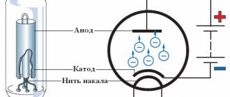
How to check the stator magnetic field at the factory
When voltage is applied to a working electric motor, a rotating magnetic field is created. It is visually assessed using a metal ball that repeats the rotation.
I do not encourage you to repeat such an experience. This example is intended to help you understand that the operation of an asynchronous motor is based on the interaction of the magnetic fields of the stator and rotor.
Only the correct connection of the windings ensures the rotation of the ball or rotor.
Motor power and winding wire diameter
These are two interrelated quantities because the cross-section of the conductor is selected based on its ability to withstand heating from the current flowing through it.
The thicker the wire, the more power can be transmitted through it with acceptable heating.
If there is no plate on the engine, then its power can be judged by two signs:
- The diameter of the winding wire.
- Dimensions of the magnetic core.
After opening the stator cover, analyze them visually.
How to connect an electric motor using different circuits?
In the diagram with a triangle, everything is simple: both contacts are connected to the network, and then one is passed through a capacitor and connected to the main winding. When the engine is not loaded, the rotor rotates and there are no problems with this. However, if there is a high load at startup, then there will either be no rotation at all, or it will be minimal. In this case, another capacitor is installed, but for starting. Immediately after this, it turns off and discharges, so it only works for a few seconds in the whole process.
When choosing a star, the capacitor is brought out to the ends of the winding. Two of them are connected to the network, and the free part closes the engine starting circuit. The easiest way to calculate the capacitance of a capacitor is through special online calculators, since it is easy for a beginner to get confused when using the formula.
When creating a power circuit for an electric motor, there are several more main points:
- There is always one branch from the main current source to the capacitor, which works not only at startup, but also at other times.
- In front of this there is a branch on which the switch is placed, sometimes additional elements conducting current are placed there.
- There is always a capacitor after the switch, which turns on at startup. It is only needed for the rotor to gain momentum.
- All capacitors that are located in the diagram go to the electric motor.
The working element is always connected to the network, so to prevent problems it is placed parallel to the starting device.
Useful tips
- Capacitors always retain high voltage at their terminals, so these devices should always be fenced.
- When working with these elements, it is necessary to pre-discharge them.
- An electric motor with a power of more than 3.0 kW cannot be connected to an alternating current network. Machines and other devices included in the wiring diagram will burn out.
- The operating voltage of paper capacitors is half the nominal voltage indicated on their case.
How to select this element?
When using the calculator, you will have to enter several parameters that determine the recommended type of device:
- Winding method. When selecting a star, all ends are fixed at one node, which is considered the zero point. In a triangle, the wires are arranged so that one of them immediately passes into the other. These parameters determine the recommended capacitor capacity.
- Voltage. The information is specified on the device tag; in standard versions it is 220 or 380 V.
- Power. The characteristics of the electric motor are also taken into account and are usually considered the determining factor. Therefore, if in doubt, they focus on power.
- Efficiency The manufacturer is also required to indicate this point. In modern models, the efficiency reaches more than 80%. If this point is not specified, then it is determined independently according to the device model. Efficiency changes over time and decreases as the engine wears out.
- Power factor. This value does not change; for stable devices it is 0.9.
If you find out each of these points and enter the indicators in the appropriate fields, the calculator will perform the calculation on its own. This method is considered preferable because it takes into account the main factors.
Additionally, when choosing a capacitor, they look at the size of the device, although this usually does not cause problems. Devices with increased capacity are larger in diameter, and they also have increased exit distances. The maximum dimensions do not exceed 50 mm, while the capacity is 400 microfarads.
If you take a responsible approach to choosing a capacitor and determine a suitable circuit, then there will be no problems connecting the element to the electric motor.
Why is a 220 V motor started via a capacitor?
First, let's define the terminology. A capacitor (Latin condensatio - “accumulation”) is an electronic component that stores electrical charge and consists of two closely spaced conductors (usually plates) separated by a dielectric material. The plates accumulate electrical charge from the power source. One of them accumulates a positive charge, and the other accumulates a negative charge.
Capacitance is the amount of electrical charge that is stored in an electrolyte at a voltage of 1 Volt. Capacitance is measured in units of Farad (F).
The method of connecting the motor through a capacitor - this method is used to achieve a soft start of the unit. On the stator of a single-phase motor with a squirrel-cage rotor, another winding is placed in addition to the main electrical winding. Two windings are related to each other at an angle of 900. One of them is working, its purpose is to make the motor work from a 220 V network, the other is auxiliary, needed for starting.
Let's look at the capacitor connection diagrams:
- with switch,
- directly, without a switch;
- parallel connection of two electrolytes.
Asynchronous or collector: how to distinguish
In general, you can distinguish the type of engine by a plate - a nameplate - on which its data and type are written. But this is only if it has not been repaired. After all, anything can be under the casing. So if you are not sure, it is better to determine the type yourself.
This is what a new single-phase capacitor motor looks like
How do collector motors work?
You can distinguish between asynchronous and commutator motors by their structure. The collectors must have brushes. They are located near the collector. Another mandatory attribute of this type of engine is the presence of a copper drum, divided into sections.
Such motors are produced only as single-phase ones; they are often installed in household appliances, as they allow one to obtain a large number of revolutions at the start and after acceleration. They are also convenient because they easily allow you to change the direction of rotation - you just need to change the polarity. It is also easy to organize a change in the rotation speed by changing the amplitude of the supply voltage or its cutoff angle. That is why such engines are used in most household and construction equipment.
Commutator motor structure
The disadvantages of commutator motors are high operating noise at high speeds. Remember a drill, an angle grinder, a vacuum cleaner, a washing machine, etc. The noise during their operation is decent. At low speeds, commutator motors are not so noisy (washing machine), but not all tools operate in this mode.
The second unpleasant point is that the presence of brushes and constant friction leads to the need for regular maintenance. If the current collector is not cleaned, contamination with graphite (from brushes being worn out) can cause adjacent sections in the drum to become connected and the motor simply stops working.
Differences between starting and running capacitors
The starting capacitor is needed to start the motor, so it works for a short time at the beginning, after which it turns off, while the motor continues to work (a phase shift is created in the winding). Consequently, the time when the starting capacitor is activated is about 3 seconds, since over a longer period it can become very hot and lead to a short circuit in the motor circuit, which will certainly be followed by failure of the circuit elements.
This type of capacitor is used on electric motors whose connection diagram provides for this starting mode. For other engines, it can also be used if, at the moment of starting, an increased load is created on the shaft, which does not allow the rotor to rotate freely.
The working capacitor sets the phase shift for constant operation of the engine, therefore it is calculated taking into account longer operation. During a cycle phase change, a voltage appears on the capacitor that exceeds the supply voltage. This occurs due to the fact that, together with the winding, an oscillatory circuit is created. The latter is also important to consider.
Comparison of both types of capacitors
The working and starting capacitors have the following differences:
- Use in various connection circuits: working and starting.
- The working capacitor generates an electromagnetic field for the main cycle of engine operation; the starting capacitor sets the phase shift between two windings - working and additional - at the beginning of operation.
- The first is connected in series with the auxiliary winding, the second in parallel with the main winding.
- The working capacitor is active all the time while the engine is on, the starting capacitor is only at the start until it reaches constant mode.
- As already noted, the principle of selecting a container is also different. Every 100 W corresponds to 7 µF for the running capacitor and 13-17 µF for the starting capacitor. The coefficient of increase in the maximum permissible voltage is also different compared to the nominal one: for operating voltage - 1.15, starting voltage - 2-2.5.
These rules help to at least roughly understand what kind of capacitor is needed to start an electric motor.
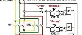
Reversing the direction of movement of the engine
If, after connecting, the motor works, but the shaft does not rotate in the direction you want, you can change this direction. This is done by changing the windings of the auxiliary winding. This operation can be performed by a two-position switch, the central contact of which is connected to the output from the capacitor, and to the two outer terminals from “phase” and “zero”.
Source
Briefly about the main thing
You can connect a 380 to 220 volt electric motor in 4 main ways:
- With capacitor.
- Without capacitor.
- With reverse.
- Star-delta design.
Before starting connection work, it is necessary to determine and verify how the winding is connected in the terminal box, and also find out the necessary characteristics from the technical table. You can perform electrical work if you have experience, but it is better to entrust it to professionals with the appropriate permit.
Ratings 0