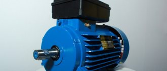
Connecting a three-phase asynchronous electric motor
A three-phase asynchronous electric motor and its connection to the electrical network often raises a lot of questions. Therefore, in our article we decided to consider all the nuances associated with preparing for switching on, determining the correct connection method and, of course, we will analyze possible options for switching on the engine. Therefore, we will not beat around the bush, but will immediately begin to analyze the questions posed.
Where you should definitely start connecting the engine: 2 important time-tested points
Before turning on any electric motor for the first time, it is necessary to clarify its structure: the design of the stator and rotor, the condition of the bearings.
From my own and other people’s experience, I can assure you that it is easier to loosen a few nuts, inspect the internal structure, identify defects at the initial stage and eliminate them, than to deal with complex repairs that could have been prevented after starting a short operation.
Important Warning
Novice electricians quite often create engine malfunctions themselves, violating the technology for disassembling it, working with an ordinary hammer: they break the edges of the shaft.
To preserve the structure of parts without damaging them, it is necessary to use a special electric motor bearing puller.
In the most extreme case, when it is not available, blows with a hammer are applied through thick plates of soft metal (copper, aluminum) or dense dry wood (apple tree, pear tree, oak).
How bearing condition affects engine performance
Any asynchronous electric motor (IM) has a rotor with squirrel-cage windings. A current is induced in them, creating a magnetic flux that interacts with the rotating magnetic field of the stator, which is its source of movement.
The rotor inside the housing is mounted on bearings. Their condition greatly affects the quality of rotation. They are designed to ensure easy sliding of the shaft without backlash or runout. Any violations are unacceptable.
The fact is that the stator winding can be considered as an ordinary electromagnet. If the rotor's bearings are broken, then under the influence of the magnetic field it will begin to be attracted, approaching the stator winding.
The gap between the rotating and stationary parts is very small. Therefore, touching or beating the rotor can touch, scratch, or deform the stator windings, irreversibly damaging them. The repair will require a complete rewinding of the stator, and this is a very difficult job.
Be sure to disassemble the electric motor before connecting it, and carefully inspect its entire internal structure.
Pay special attention to the condition of the bearings, compliance with tolerances and fits, and quality of lubrication. Dry and old lubricant must be replaced with fresh one.
What should be taken into account in the design of stator windings and how to prepare them
The home mechanic most often comes across electric motors that have already been used somewhere, and, perhaps, have undergone reconstruction or rewinding. Nobody usually declares this, the information on nameplates and tags is not changed, it is left the same. Therefore, I recommend visually inspecting their insides.
Stator coils for asynchronous motors for power supply from single-phase and three-phase networks differ in the number of windings and design.
A three-phase electric motor has three absolutely identical windings, spaced apart in the direction of rotation of the rotor by 120 angular degrees. They are made of one wire with the same number of turns.
They all have equal active and inductive resistance and occupy the same number of slots inside the stator.
This allows you to initially assess their condition with a conventional digital multimeter in ohmmeter mode with the voltage turned off.
A single-phase induction motor has two different windings on the stator, separated by 90 angular degrees. One of them is designed for long-term passage of current in the nominal operating mode and is therefore called the main, main or working.
To reduce heating, it is made with a thicker wire that has lower electrical resistance.
A second winding of greater resistance and smaller diameter is mounted perpendicular to it, which makes it possible to distinguish it visually. It is designed for short-term flow of starting currents and turns off immediately when the rotor reaches the rated speed.
The starting or auxiliary winding occupies approximately 1/3 of the stator slots, and the rest is allocated to the working turns.
However, this rule has exceptions: in practice, there are single-phase electric motors with two identical windings.
To connect the stator to the power supply, the ends of the windings are brought out with wires. Taking into account the fact that one winding has two ends, a three-phase electric motor can, as a rule, have six terminals, and a single-phase motor can have four.
But there are exceptions to this simple rule related to internal switching of pins to simplify installation on special equipment:
- for three-phase motors, the following can be removed from the stator: three wires when internally assembling a delta circuit;
- or four - for a star;
- three outputs with internal combination of one end of the starting and working windings;
- or six ends for a design with a starting winding and a built-in contact for disconnecting it from the centrifugal regulator.
As you can see, it is possible to judge the design of an asynchronous motor by the number of wires connected to the terminal block from the stator windings, but the probability of error is quite high. A more thorough analysis of its structure is needed.
Technical condition of winding insulation
Where and under what conditions the stator was stored is not always known. If it was unprotected from precipitation or inside wet rooms, then its insulation requires drying.
At home, the disassembled stator can be placed in a dry room to dry. It is possible to speed up the process by blowing a fan or heating with conventional incandescent lamps.
Make sure that the heated glass of the lamp does not touch the winding wire; ensure an air gap. The end of the drying process is associated with the restoration of the insulation properties. This process must be controlled by measurements with a megohmmeter.
Main technical characteristics
Depending on the class of the electric motor, its technical characteristics vary. Within the framework of this article, the task of bringing the parameters of all existing classes of engines is not set. We will focus on describing the main technical characteristics for electric motors of classes 56 A2 - 80 B2.
In this small gap in the line of models of electric motors with squirrel-cage rotors, the following can be noted:
Power ranges from 0.18 kW (class 56 A2) to 2.2 kW (class 80 B2).
Current at maximum voltage – from 0.55 A to 5A.
Efficiency from 66% to 83%.
The shaft rotation speed for all models from the specified range is 3000 rpm.
The technical characteristics of a particular engine are indicated in its passport.
Connection diagram for an asynchronous motor with a starting winding: assembly sequence
For example, we have determined that there are four or three wires coming out of the stator. We call up the active resistance between them with an ohmmeter and determine the starting and operating windings.
Let’s assume that four wires have two pairs with resistances of 6 and 12 ohms connected to each other. Let's randomly twist one wire from each winding, designate this place as a “common wire” and get a measurement of 6, 12, 18 Ohms between the three terminals.
I marked the beginnings of the windings with dots on this diagram. For now, ignore this question. But, you will need to return to it further when the need arises to reverse.
The chain between the common terminal and the lower resistance 6Ω will be the main one, and the larger 12Ω will be the auxiliary, starting winding. Connecting them in series will show a total result of 18 ohms.
We mark these 3 ends with markings that are already clear to us:
- O - general;
- P - starting;
- R - worker.
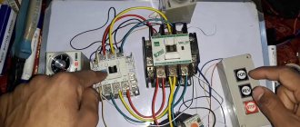
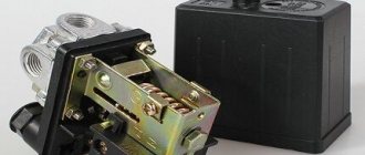
Next we need a PNVS button, specially designed for starting single-phase asynchronous motors. Its electrical circuit is represented by three closing contacts.
But, it has an important difference from the start button of three-phase NVD electric motors: its middle contact is made with self-return, and not fixed when pressed.
This means that when the button is pressed, all three contacts are closed and held in that position. But, when you release your hand, the two outer contacts remain closed, and the middle one returns under the action of the spring to the open state.
We connect this button and the terminals for the output of the stator windings from the electric motor with a three-core cable so that the starting winding contact goes to the middle contact of the PNVS. We connect pins P and P to its outermost contacts and mark them.
On the back side of the button, between the contacts of the starting and working windings, we rigidly mount a jumper. We connect a 220 volt household power cable with a plug for installation in a socket to it and the second outer contact.
When this button is turned on, all three contacts will close, and the working and starting windings will begin to work. In just a couple of seconds the engine will finish accelerating and return to nominal mode.
Then the start button is released:
- the starting winding is switched off by self-return of the middle contact;
- the main winding of the motor continues to spin the rotor from a 220 V network.
This is the most affordable connection diagram for an asynchronous motor with a starting winding for the home craftsman. However, it requires the presence of a ventilator button.
If it is not there, and the electric motor urgently needs to be started, then it can be replaced with a combination of a two-pole circuit breaker and a conventional electric button of the appropriate power with self-reset.
You will have to turn them on at the same time, and release the button after spinning up the electric motor.
Always perform all starts of electric motors and any electrical equipment with the protection of these circuits by circuit breakers. They will prevent the development of emergency situations when any random errors occur.
In order to consolidate the material on this topic, I recommend watching the video of the owner Oleg pl. It just shows the design of a built-in centrifugal regulator designed to automatically turn off the auxiliary winding.
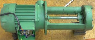
Operation of devices with a specific moving part
The usual version of the rotor assembly of a three-phase asynchronous electric motor is a short-circuited “squirrel cage” type, which is assembled from steel plates. When there is a need to reduce the rating of starting currents with the ability to regulate the rotation speed, then a wound rotor is used. Its characteristic feature is two groups of conclusions:
- Stator. Classic terminal block to which mains voltage is supplied (380 or 220V),
- Rotary. Additional terminal block for the terminals of the wound rotor windings, to which the contacts of the rheostat (resistance block) are connected.
The latter is necessary for a smooth start with gradual switching on/off of individual resistances in the wound rotor winding circuit.
Wiring diagram for an asynchronous motor with capacitor start: 3 technologies
The stator with windings for starting from capacitors has approximately the same design as discussed above. It is difficult to distinguish it by appearance and simple measurements with a multimeter, although the windings may have equal resistance.
Refer to the nameplate and table from Aliyev’s book. You can try to connect such an electric motor using a circuit with a PNVS button, but it will not spin up.
It will not have enough starting torque from the auxiliary winding. It will hum and twitch, but will not reach the rotation mode. Here you need to assemble a different capacitor starting circuit.
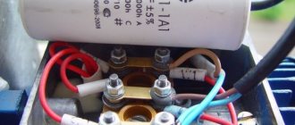
The 2 ends of different windings are connected to a common terminal O. A household voltage of 220 volts is supplied to it and the second end of the working winding through an AB switching device.
The capacitor is connected to the terminals of the starting and operating windings.
As a switching device, you can use a double circuit breaker, a switch, NVD or NVDS type buttons.
Here it turns out that:
- the main winding operates directly from 220 V;
- auxiliary - only through the capacitor.
This circuit is used for easy starting of capacitor electric motors that are put into operation without heavy load on the drive, for example, fans, sanders.
If, at the moment of starting, it is necessary to simultaneously spin the belt drive, gear mechanism of the gearbox or other heavy drive, then a starting capacitor is added to the circuit, which increases the starting torque.
It is convenient to describe the operating principle of such a scheme using the same PVS button.
Its self-resetting contact is connected to the auxiliary winding through an additional starting capacitor Sp. The second end of its plate is connected to terminal P and working capacity Cp.
An additional capacitor at the moment of starting an electric motor with a heavy drive helps it quickly reach its rated rotation speed, and then simply turns off so as not to create overheating of the stator.
This circuit is fraught with one danger associated with long-term storage of a capacitive charge by the starting capacitor after removing power 220 when the electric motor is turned off.
If the worker is not careful or careless, the discharge current can pass through the human body. Therefore, the charged capacity must be discharged.
In the scheme under consideration, after removing the voltage and pulling out the plug and power cord from the socket, this can be done by briefly turning on the PVS button. Then the capacitance Sp will begin to discharge through the starting winding of the motor.
However, not all people do this for various reasons. Therefore, it is recommended to install two additional resistors in the starting circuit.
Resistance Rр is selected with a nominal value of about 300÷500 Ohms of several watts. Its task is to discharge the auxiliary capacitance Sp after removing the supply voltage.
The Ro resistor is low-resistance and powerful and acts as a current-limiting resistance.
Adding resistors to the electric motor starting circuit increases the safety of its operation and automatically limits the flow of capacitive discharge current of a charged capacitor through the human body.
Where can I get the values of the main and auxiliary capacitors?
The fact is that the factory determines the value of the starting and operating capacitance for capacitor starting of a single-phase IM individually for each model and indicates this value in the passport.
There are simply no separate formulas for calculating how it is done for capacitor starting of a three-phase motor in a single-phase network using star or delta circuits.
You will need to look for factory recommendations or experiment during the setup process with different containers, choosing the most optimal option.
The owner of the video “IV I'm Interested” shows how to optimally configure the parameters of a capacitor motor starting circuit.
Operation of DPT type P 41
An electric machine, powered by 220 V DC, has a more complex design compared to the units described above. The specifics of operation, for example, of the P 41 model, require the presence of a commutator-brush assembly, an armature coil, and auxiliary stator (inductor) poles. Motors of this model size belong to machines with an electromagnetic inductor. That is, to connect and start P 41, it is not permanent magnets that are used, but an independent or mixed excitation winding of 110 or 220V.
As you can judge, the operation of three-phase (380 V) and single-phase (220 V) AC machines or DFC type P 41 can be organized in a variety of ways, from classical to specific ones, taking into account actual operating conditions.
Three-phase and single-phase motors
Motor connection diagrams star, delta
Before discussing the connection of a star/delta motor, let's read the theory. Three-phase and single-phase motors are sometimes equipped with three connection wires. Stop walking too far. Let's take the following two cases:
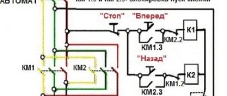
- The three-phase motor has internal winding commutation using a star circuit. The poles are provided with one common point. Three phases are connected to opposite ends of the windings. The coils are absolutely identical, the same. A rotating moving field is created inside, due to which the shaft moves. The rotor is represented by a silumin drum with copper veins. No current is supplied; magnetic poles are formed by induced currents. They are captured by the rotating field of the rotor, and movement begins. A design feature is the impossibility (without special measures) of connecting to a 230 volt network. It would be necessary to connect the windings using a delta circuit, which is impossible to do. Of course, you can open the stator, find a common point, make three taps, breaking the contacts between the coils. The second feature of the engine is the absence of a neutral wire. Many people are perplexed by the state of affairs - where does the current go? Charges move along wires between phases. The law of electrical engineering states: to connect three phases, the load does not need to have a common wire if the consumption of the three branches is the same. Otherwise, you will need to provide a neutral. A real-life example: let’s say you need to connect an electric kettle to 380 volts. Marasmus? Each phase has an amplitude of 230 volts, the workers want boiling water - it’s impossible to refuse. We take one of the phases and connect the other terminal of the plug to neutral. Please note that the phases within one consumer must be loaded equally (roughly speaking, give each line a kettle), otherwise negative consequences will affect the substation supply transformer.
Electrical motor switching
So, there are two engines that look similar, but need to be connected in different ways. An important part of the housing is the electric motor connection diagram. Located on the nameplate, stamped on the casing. It becomes clear how many phases the motor is designed for and how to connect it to the circuit. There is no information - we’ll try to fix the defect ourselves. You will need a Chinese tester.
For a three-phase motor, three contacts in pairs will give the same resistance equal to twice the winding rating. A 230 volt motor will give different measurement results:
- The highest indicator of the tester is between phase ends. The voltage of 220 volts is supplied directly to one, and to the other through a capacitor. Capacity strongly depends on power and shaft rotation speed. The parameter determines the average shaft load in operating mode.
- The smallest value is formed between the ends of the working winding.
- The third denomination occupies an intermediate position. The sum with the resistance of the working winding is equal to the first item in the list.
We connect the neutral between the windings and remove the imbalance current. The thickness of the wiring is half that of the phases. The method of disconnecting the starting winding at the right moment uses start-up relays. There is no manual control.
The issue of acquiring a node is closely related to the use of special directories. A foreign start-up protection relay must absolutely not be used with this type of electric motor. There is a high probability of incorrect operation and failure of the device. Almost craftsmen manually break the chain. The method is wrong, it has the right to exist.
We add that the loss of one phase can negatively affect some types of motors. When experimenting with the unit, implementing a star-delta motor connection, try to avoid situations. It is customary to carry out the launch with special protective circuit breakers that cut off the power when danger arises.
How to prepare for connection
To correctly turn on a three-phase motor, you must remember that there are several winding connection diagrams, including:
- "Star". Some ends of the winding are connected together, and the other ends are connected to the phase wires of the network;
- "Triangle". All three windings are connected in series - the end of each winding with the beginning of the next. Mains voltage is supplied to the connection points.
You might be interested in this Description of the push-button control station
Note! To obtain the same power, a star connection requires a voltage √3 times greater than a delta connection. For engines that allow arbitrary switching of windings, the operating voltage “220/380” or “127/220” must be indicated on the nameplate. The first value refers to the delta connection, the second to the star connection.
Engine block, star connection
In such electric motors, the beginning and ends of all windings are connected to the terminal block in pairs in three rows:
- the beginning of the first winding - the end of the second;
- the beginning of the second - the end of the third;
- the beginning of the third - the end of the first.
Motor block, delta connection
For a star connection, connect one row of three terminals with two jumpers, and for a delta connection, close each pair with three jumpers.