An electromagnetic starter is a low-voltage combined electromechanical device specialized for starting three-phase electric motors, to ensure their continuous operation, to turn off the power, and in some cases to protect the electric motor circuits and other connected circuits. Certain engines have a motor reverse function.
In essence, an electromagnetic starter is an improved, modified contactor. But more compact than a contactor in the usual sense: lighter in weight and designed directly for working with motors. Certain modifications of magnetic starters are optionally equipped with a thermal microrelay for emergency shutdown and protection against phase loss.
To control the start of the motor by closing the contacts of the device, a key or a low-current group of contacts is intended:
- with a coil for a certain voltage;
- in some cases, both.
In the starter, the coil in the metal core is directly responsible for switching the power contacts, to which the armature is pressed, pressing on the contacts and closing the circuit. When the power to the coil is turned off, the return spring moves the armature to the opposite position - the circuit opens. Each contact is located in a special arc-extinguishing chamber .
What is the difference between a magnetic reversing starter circuit: configuration rules
Let's imagine that there is a need to understand the features of a device in which an electric motor is capable of operating in two directions - forward and reverse, that is, reversible. And if such a feature is obvious, it means that the circuit of the unit provides for the presence of a magnetic reversing starter. Its use is not so simple; it is necessary to consider the operating mode in order to prevent dangerous phase short circuits.
In the diagram you can definitely find the designation of an additional control circuit and a reverse start button. Due to such thoughtfulness, the created circuit is reliable, as it is protected from short circuits.
What causes the reverse? This is easy to explain. – Due to the reversal of the two phases present in the system: when one stops working, and the other, on the contrary, starts. For more reliable protection, a blocking must be thought out in the circuit, which is responsible for the accurate and timely stopping of one of the starters, the first or the second. It all depends on the tasks assigned. Let us remind you that if two starters are triggered, a short circuit will instantly occur on the power contacts of the unit.
Note that the reverse movement does not start instantly, since the activation of several important points is required. Firstly, it is definitely recommended to stop the engine and press the “Stop” button
Secondly, you need to pay attention to the condition of the coil, remove the voltage from it, otherwise the reverse starting process will fail. If everything is done correctly, the starter will return to its original position under the action of the spring
That's it, the unit is ready for reverse. We press the “Start” button, accordingly, the required voltage is supplied to the coil, which means the process has started. From the control panel of the device you can read information about the closure of the electrical circuit. This means that current has entered the system, and it is gradually supplied to the coil. At the same time, all contacts that have not started working are blocked. Security requires this.
Please note that if the thermal relay is triggered, the unit will stop to avoid an emergency.
Thus, the magnetic starter plays an important role in the operation of motors. The reversing starter also deserves its place, ensuring uninterrupted operation of machines, heating elements, elevators and other electrical equipment. The starters are reliable and safe, especially if they are additionally equipped with system locking mechanisms. They are located inside the casing and do not allow two coils to operate simultaneously, without leading to a phase short circuit.
{SOURCE}
Design and principle of operation of an electric motor
An electric motor is a device in which the working part rotates under the influence of an electromagnetic field. The main components here are a stationary stator and a rotor moving around its axis. Pulsed electromagnetic waves are created in the stator part, driving the rotor part. As a rule, the more powerful the electric drive, the larger the overall dimensions of the motor. Although modern technology tends to miniaturize, you can find quite powerful models of quite compact size on the market.
Of the many varieties of electric power units, the most common are:
- commutator motors (short-circuited), where the rotor is powered and driven by so-called brushes, which in turn interact with the commutator lamellas;
- asynchronous motors operating under the influence of inductive forces arising in a magnetic field.
For example, consider a typical asynchronous model. Here the power is connected to the stator windings, resulting in electromagnetic waves being generated. With alternating voltage, an unstable field arises, characterized by a certain frequency of oscillations that displace the rotor. For unhindered movement, a small gap is specially left between the stator and rotor parts. The windings installed on the stator interact with the rotor windings, creating an electromotive force. In this case, the resulting magnetic waves move in different directions relative to the stator, which is why such a motor is called asynchronous. Most often, three phases are used to connect it, but if necessary, most models can be adapted to operate from a single-phase network.
Changing Rotational Movement
Now, to give the opposite direction of movement, you need to change the position of the power phases, which is convenient to do using the KM2 switch.
Everything happens thanks to the opening of the first phase. In this case, all contacts return to their original position, de-energizing the motor winding. This phase is the standby mode.
Using the SB3 button activates a magnetic starter with the abbreviation KM2, which, in turn, changes the position of the second and third phases. This action causes the motor to rotate in the opposite direction. Now KM2 is the leader and until it opens, KM1 will not be used.
Required components
You can organize a reverse connection on your own without much difficulty if you have a reverse start circuit at hand. An important component that greatly facilitates the process of installing and commissioning an electric motor is the contactor, which can be part of a magnetic starter. Of course, you can adapt a simple switch or circuit breaker to turn the unit on/off. This option is allowed, but for normal operation of the electric motor, sufficiently large starting currents are required, which can be dangerous for operating personnel and equipment.
If a breakdown occurs during switching on, the operator’s health may be harmed, and the reversible electric motor itself and the switch will fail. Therefore, to minimize the risk of electric shock, it is advisable to use a contactor that is separated from the part with which a person directly interacts. Modern devices of this type have a separate modular unit with a coil that generates an electromagnetic field. To operate such a coil, a voltage of 12 volts or more is usually sufficient. When current flows from the power source to the iron core with the contact plate attached, it is drawn inward and closes the contact group, causing the electric motor to start. When the supply voltage disappears, the core returns to its original state and the contacts open.
Specifications
We will not consider all the parameters of the device here, because the choice is always made based on the size of the starter, which is characterized by the rated load current acting on the contacts of the device. There are seven starter values, each of which corresponds to the permissible current load. The photograph below shows these same values and in what areas such magnetic starters are used.
It should be noted that small errors in the parameters are acceptable. But in some cases it is necessary to take into account the range in which the thermal relay operates. If the starters have an overestimated load, and the relays have an underestimated minimum thermal shutdown value, then there may be a mismatch with the specified power of the electrical circuit or consumer.
{SOURCE}
Magnetic starter connection diagrams.
The first, classic scheme, is intended for the usual start of an electric motor: the “Start” button is pressed - the engine turns on, the “Stop” button is pressed - the engine turns off. Moreover, instead of a motor, you can connect any load, for example, a powerful heating element.
For ease of understanding, the circuit is divided into two parts: power part
and
control circuits
.
Power section
powered by three-phase alternating voltage 380V with phases “A” “B” “C”.
The power part includes: three-pole circuit breaker QF1
, three pairs of power contacts of the magnetic starter
1L1-2T1
,
3L2-4T2
,
5L3-6T3
and a three-phase asynchronous electric.
engine M.
_
Control circuit
receives power from phase “A”.
The control circuit diagram includes the SB1
“Stop” button, the
SB2
“Start” button, the magnetic starter coil
KM1
and its auxiliary contact
13NO-14NO
, connected
in parallel with
the “Start” button.
When turning on the QF1
phases “A”, “B”, “C” arrive at the upper contacts of the magnetic starter
1L1
,
3L2
,
5L3
and are on duty there.
Phase “A”, which supplies the control circuits, comes through the “Stop” button to contact No. 3
of the “Start” button, the auxiliary contact of the starter
13NO
and also remains on duty at these two contacts. The circuit is ready for use.
When you press the “Start” button, phase “A” hits the coil of the KM1
, the starter is triggered and all its contacts are closed.
Voltage appears at the lower power contacts 2T1
,
4T2
,
6T3
and from them is supplied to the electrical circuit. engine. The engine starts to rotate.
You can release the "Start" button and the engine will not turn off, since using the auxiliary contact of the starter 13NO-14NO
, connected
in parallel to
the “Start” button,
self-recovery
.
It turns out that after releasing the “Start” button, the phase continues to flow to the coil of the magnetic starter, but through its 13NO-14NO
. In the lower figure, the arrow shows the movement of phase “A”.
And if there is no self-recovery, you will have to keep pressing the “Start” button all the time while the electric power is working. motor or any other load powered by a magnetic starter.
To turn off email. engine, just press the “Stop” button: the circuit will break, the control voltage will stop flowing to the starter coil, the return spring will return the core with the power contacts to its original position, the power contacts will open and disconnect the engine from the three-phase supply voltage.
Now let's look at the editing room
starter control circuit diagram. Here everything is almost the same as in the circuit diagram, with the slight exception of the implementation of self-retaining.
In order not to pull an extra wire to the “Start” button, a jumper is placed between the coil output and one of the nearby auxiliary contacts: in this case it is “ A2
" and "
14NO
".
And from the opposite auxiliary contact the wire runs directly to contact No. 3
of the “Start” button.
Well, you and I have analyzed a simple classic diagram for connecting a magnetic starter. Also, on one starter you can assemble an automatic transfer switch (ATS) circuit, which is designed to ensure uninterrupted power supply to consumers.
Well, if you have any questions or doubts about the operation of the starter, then watch the video, from which you will additionally obtain the necessary information.
The next circuit will be a little more complicated than this one, since it will involve two magnetic starters and three buttons and this circuit is called reversible. Using such a scheme, it will be possible, for example, to rotate the engine left or right, raise and lower the winch.
Until then, goodbye. Good luck!
Starter capabilities
To limit the starting current of a three-phase motor, its windings can be connected in a star, then, if the motor has reached its rated speed, switch to a delta. In this case, magnetic starters can be: open and in a housing, reversible and non-reversible, with and without overload protection.
Each electromagnetic starter has blocking and power contacts. Power switches loads. Interlocking contacts are needed to control the operation of the contacts. Blocking and power contacts can be naturally open or normally closed. In circuit diagrams, contacts are shown in their normal state.
The ease of use of reversing starters cannot be reviewed. This includes operational control of three-phase asynchronous motors of various machines and pumps, and control of the ventilation system, fittings, right down to the locks and valves of the heating system. The possibility of remote control of starters is especially noteworthy if the electrical source of remote control switches the starter coils in a similar way to relays, and the latter safely connect power circuits.
More about deadlock
The electrical circuit for reversing starting of an asynchronous motor requires an interlock. It is worth understanding that to change the direction of rotation of an asynchronous motor, you need to swap any 2 phases. To do this, the starter inputs are connected directly, and the output is connected crosswise across any 2 phases. If both starters are turned on at the same time, a short circuit will occur, which will most likely burn out the power contact groups on the starters.
You may be interested in: Boyle-Mariotte Law: formula and example problem
In order to avoid a short circuit when installing a reversible motor start, it is necessary to prevent the simultaneous operation of both starters. This is why it is necessary to use an interlocking scheme. When the first starter is turned on, the power to the second starter is interrupted, which prevents its accidental activation, for example, both “start” buttons are pressed simultaneously.
If it turns out that when you press the button that should turn on “rotation to the right,” the engine rotates to the left, and, conversely, when you press “rotation to the left,” the engine rotates to the right, you should not reassemble the entire circuit. Just swap 2 wires at the input - that's all, the problem is solved.
It may happen that this is impossible to do at the input due to some circumstances. In this case, swap the 2 wires in the brand box on the engine. And again the problem is solved. The right spin button will spin right, and the left spin button will spin left.
Description of the operation of the above circuit
You may be interested in: Lictor is: the essence of the profession and historical facts
Let's analyze the operation of the circuit diagram of reverse engine starting. The current flows from phase C to the normally closed common button KnS, the “stop” button. After which it passes through a general current relay, which will protect the engine from overloads. Then, when you press the switch “right”, the current passes through the normally closed contact of the KM2 starter. Entering the coil of the KM1 starter, the core is retracted, closing the power contacts, breaking the power to the KM2 starter.
This must be done in order to interrupt the power supply to the second starter and protect the circuits from short circuits. After all, reverse is ensured by the fact that any 2 phases change places. Thus, if you press the “left” KnP button when KM1 is turned on, the start will not occur. Self-shunting is provided by an auxiliary contact, shown under the “right” control panel. When the starter is turned on, this contact is also closed, providing power to the starter coil.
In order to stop the engine, you must press KnS (“stop”), as a result of which the starter coil will lose power and return to normal. Now that KM1 has returned to its normal state, it has closed the normally closed group of auxiliary contacts, thanks to which the KM2 starter coil can again receive power, and it has become possible to start rotation in the opposite direction. To do this, press the control button “left”, thereby turning on the KM2 starter. Receiving power, the coil draws in the core and closes the power contacts, turning on power to the motor, swapping 2 phases.
Analyzing the operation of this circuit for reversing engine starting, you can notice that the bypass is provided by a normally open auxiliary contact, shown under the “left” switchgear button, and it cuts off the power to the KM1 starter, making it impossible to turn it on.
The circuit for a three-phase drive was discussed above. At the very beginning of the circuit, immediately after the KnS, you can see a normally closed contact from the current relay. If the motor consumes excessive current, the relay is activated, cutting off power to the entire control circuit. Everything that works in the control circuit will lose power, this will save the engine from failure.
Conventional non-reversible switching circuit
The simplest switching option is considered to be a non-reversible circuit, which ensures rotation of the electric motor shaft in only one direction. As an example, we can take a conventional starter with a 220 V control coil.
The connection of the circuit begins in a three-phase circuit breaker, approaches the power terminals of the starting device, and then connects to a thermal relay. The control coil on one side is connected to the neutral conductor, and on the opposite side to the phase by using functional buttons in this circuit.
The push-button station includes two buttons: START - with normally open contacts and STOP - with normally closed contacts. Simultaneously with the start button, a normally closed contact of the control coil element is connected. Due to the thermal relay included in the gap of the phase line, the motor is protected from excessive overloads. Its normally closed contact is connected to the control elements.
When the three-phase circuit breaker is turned on, current begins to flow towards the power contacts of the starting equipment and to the control circuit. After this, the circuit comes into working condition. To start the electric motor, pressing the start button is sufficient. Next, power is supplied to the control components. The circuit turns out to be closed, after which the armature begins to retract and at the same time close the contact of the control device. Current is supplied to the power contact group of the motor, and the shaft begins to rotate. After the start button returns to its original state, power will be supplied to the contactor winding, passing through the auxiliary contact, due to which the engine will continue to operate without interruption.
It is possible to stop the operation of a non-reversible unit using the available STOP button. This will cause an open circuit, and the supply voltage will no longer reach the control unit. The opening of the shunt contact begins and the armature returns to its original state with the simultaneous opening of the main contacts. At the end of this process, the electric motor stops. When the STOP button is released, the contact of the control element will remain in the open position until the next start of the circuit.
To protect the electric motor during irreversible starting, a thermal relay based on bimetallic contact plates is used. Under the influence of increasing current they begin to bend. Since the e-plates are connected to the release, a contact in the control winding interrupts the supply voltage. The contacts of the device are disconnected and return to their original state.
General diagram of electric motor reverse
Various types of three-phase asynchronous electric motors are widely used in industry and agriculture. They are installed in electric drives of equipment and serve as an integral part of automatic devices. Three-phase units have gained popularity due to their high reliability, simple maintenance and repair, and the ability to operate directly from the AC mains.
The specific operation of devices operating with electric motors requires a change in the direction of shaft rotation, called reverse. For such situations, special circuits have been developed, which include additional electrical devices. First of all, this is an input machine that has the appropriate parameters, contactors (2 pcs.), a thermal relay and controls in the form of three buttons combined into a common push-button station.
In order for the shaft to start rotating in the opposite direction, it is necessary to change the phase arrangement of the supplied voltage. Constant monitoring of the voltage supplied to the electric motor and contactor coils is necessary. The direct implementation of reverse in a three-phase motor is carried out by contactors (CM) No. 1 and No. 2. When contactor No. 1 is activated, the phases of the incoming voltage will be located differently than when contactor No. 2 is activated.
To control the coils of both contactors, three buttons are provided - FORWARD, BACK and STOP. They provide power to the coils depending on the phase arrangement. The order in which the contactors are turned on affects the closure of the electrical circuit in such a way that the rotation of the motor shaft in each case occurs strictly in a certain direction. The BACK button only needs to be pressed, but not held, since it itself turns out to be in the desired position under the action of self-retaining.
All three buttons are locked to prevent them from being activated at the same time. Failure to comply with this condition may result in a short circuit in the electrical circuit and equipment failure. To block the buttons, a special contact block located in the corresponding contactor is used.
DC machines
Reversing starting of a DC motor can be accomplished by changing the polarity of the connection of the armature winding or field winding. Depending on how these two windings are connected, DC motors have the following types of excitation:
- independent - the field and armature windings are powered from different sources;
- sequential;
- parallel;
- mixed.
DC motors can run out - a condition of machine operation in which the speed increases so much that it causes mechanical damage.
When using a commutator motor with parallel or independent excitation, this mode may occur when the excitation winding breaks. Therefore, the connection diagram of the reversible motor in this case is constructed in such a way that the armature winding is switched, and the field winding must be directly connected to the power source. That is, it is unacceptable to connect the excitation circuit through any contacts or fuses.
Otherwise, the control circuit differs from the reversible connection of a three-phase motor only in that two DC supply wires are switched instead of three AC phases.
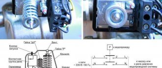
Operating principle of a reversing magnetic starter
The reversing magnetic starter is connected and operates as follows. After the “start” command is executed on the device’s control panel, the electrical circuit is closed, as a result of which current is supplied to the coil. At this time, the mechanical blocking system is activated, thus blocking unused contacts. Since the contacts of the button are also blocked, this action allows you not to hold the button, but to calmly release it. The second button of the reversing magnetic starter, in parallel with starting the device, opens the circuit, so its activation will not give any result.
To carry out the reverse, it is necessary to activate the “stop” button, pressing which will de-energize both coils of the reversing magnetic starter, thereby stopping the functional operations of the equipment. With this action, all blocking devices will take their original position. This sequence allows you to activate the reversing magnetic starter again, without any additional actions. When you select the “start” command, the above actions will occur, but the second coil will be used, and the first will be blocked.
The most advanced and safe reversing magnetic starter is equipped with additional locking system mechanisms. These devices are placed to block the operating torque, usually inside the casing (directly under the control panel) and are designed to prevent both coils from operating at once. According to the diagram of a reversing magnetic starter, if it is equipped with an electrical interlocking system, then the use of mechanical interlocks is not at all necessary.
Reverse occurs through a complete stop of the engine. In other words, when a reversing magnetic starter is triggered, the motor slows down, followed by a complete stop, and then rotates in the other direction. However, in this case it is necessary to match the power of the engine and the reversible magnetic starter. Only when this process is carried out will the reverse be carried out correctly.
If stopping and reversing the engine is carried out by back switching, then the power of the equipment should be significantly lower than the maximum permissible power of the reversing magnetic starter. Most often, the engine is 1.5-2 times inferior in power to the starter. In many ways, the difference in power depends on the quality of the contacts of the magnetic starter, or rather their wear resistance when operating under these conditions.
This mode must be carried out without the use of mechanical locking systems. However, the safety of operation of a reversing magnetic starter must be ensured by the use of electrical interlocking systems. In general, reversible magnetic starters are a technologically advanced and safe method for remote control of asynchronous electric motors.
Basic methods of engine reversal
As we wrote earlier, there are several options for implementing reverse. Above we described in detail the most common one - using a reversing starter. Let's describe other important techniques used by electricians. They have both common and distinctive features, making them different, although they perform the same task.
Opposition
This method is used when there are rapid changes in the order of switching transistor switches. When the phase sequence on a running motor changes, the rotation of the field changes accordingly. Because of this, slip occurs, generated by the rapidly increasing current of the frequency converter. The indicator reaches its maximum value, limited by the internal level of the frequency converter. When the slip is strong, the speed reference is reduced using the internal drive regulator and the braking torque is low.
When the electric motor reaches zero speed, then a reverse occurs, which fully corresponds to the acceleration lines. The energy that is not wasted on load and friction enters the rotor, where it is dissipated.
Changing direction
Here the direction of rotation of the electric motor is changed. fields when controlling the deceleration rate period. The torque of the mechanism, as is known, is directly opposite to the torque of the motor and interrupts it modulo. In simple terms, natural braking occurs several times faster than the deceleration curve set by the regulator indicates. The speed level gradually decreases, as a result of which the direction of the revolutions changes.
In situations where the torque exhibits a natural stall below the level determined by the governor, the motor operates in a “regenerative” braking mode, where the energy flows back to the converter.
Diode bridges block energy from entering the network, and filter capacitors are charged. The voltage level gradually increases, as a result of which a protective device is activated, which prevents the release of energy.
Braking mode
Also, motors with three phases easily achieve reverse if the motor is braking for a long time. In most situations, this method is used on test benches.
Braking mode for reverse example
So, when the engine operates, energy is released at high levels, which is why resistors simply cannot cope with its dissipation. To prevent temperature increases, there are special systems that work to return energy to the network. Thanks to multi-level control, all functions aimed at generating current as close as possible to the sine frequency are performed clearly and smoothly.
Magnetic starter device for reverse starting
A standard starter consists of the following components:
- a core with an induction coil attached to it;
- anchor with a mechanism for moving contact groups;
- a housing that ensures structural integrity along with protection from external influences.
When the supply current is supplied (switched off), the movement of the armature closes (disconnects) the corresponding contacts of the power circuits. Reversible modifications are created from two conventional starters installed on one mounting panel. Additional conductors provide blocking that prevents two products from being turned on at the same time.
Reversing starter
In this embodiment, separate keys are used that initiate rotation of the rotor in the forward and reverse directions. The first operating mode is accompanied by shunting of the corresponding circuit by the “KM1” contact group. If you press the Back key after this, nothing will happen.
To activate reverse rotation, you must first stop the engine to avoid damage. By pressing “Stop” (C – in the figure below), the supply voltage of 380 V is turned off. Afterwards, you can supply current to the required windings through the power contact groups “KM2”.
Connection diagram
Protection of power circuits from short circuits or “fool proof”.
As we already know, before changing the rotation of the engine, it must be stopped. But it doesn’t always work out this way, since no one is immune from mistakes. Now imagine a situation where there is no protection.
The engine rotates to the left, starter KM1
in operation and from its output, all three phases go to the windings, each to its own.
Now, without turning off the KM1
, we turn on the
KM2
.
Phases “B” and “C”, which we swapped places for reverse, will meet at the output of the KM1
.
An interphase short circuit
will occur between phases “B” and “C”.
To prevent this from happening, the scheme uses normally closed
starter contacts, which are installed in front of the coils of the same starters, and thus eliminate the possibility of turning on one magnetic starter until the other is de-energized.
Protection of motor reverse operation
Always, before changing the order of connecting a 3-phase motor, changing the order of phases on the windings of the electric motor, it is necessary to stop it. This is implemented in the switching circuit by normally closed contacts, which “safeguard” the operator’s work and prevent phase-to-phase short circuits in the electric motor when its connection is reversed. In the considered connection diagram for the reversing starter, it can be seen that only one starter can operate.
Every day there is work to connect direct and reverse rotation electric motors; the circuit diagram for switching on the starters is not difficult for qualified electricians. It must always be remembered that the function of stopping the engine must be implemented before it rotates back.
How to connect a reversing magnetic starter: diagram, description
In every installation that requires starting an electric motor in forward and reverse directions, there must be a magnetic starter for a reversible circuit. Connecting such a component is not as difficult a task as it seems at first glance. In addition, the demand for such tasks appears quite often. For example, in drilling machines, cutting machines or elevators, if this concerns non-domestic use.
The fundamental difference between this scheme and a single one is the presence of an additional control circuit and a slightly modified power section. Also, to make the switch, this installation is equipped with a button (SB3 in the figure). Such a system is usually short-circuit protected. For this purpose, in front of the coils in the power circuit there are two normally closed contacts (KM1.2 and KM2.2) derived from contact attachments located in the position of the magnetic starters (KM1 and KM2).
In order for the above diagram to be readable, the images of the circuit on it and the power contacts have different colors. Also, for simplicity, pairs of power contacts, which usually have alphanumeric abbreviations, were not indicated here. However, these issues can be found in articles devoted to connecting standard magnetic starting systems.
Operation of control circuits when the engine rotates to the left.
SB2 button
phase “A” through the normally closed contact
KM2.2
is supplied to the coil of the magnetic starter
KM1
, the starter is triggered and its normally open contacts
close
, and the normally closed contacts
open
.
When contact KM1.1
the starter is
self-retaining
, and when the power contacts
KM1
, phases “A”, “B”, “C” are supplied to the corresponding contacts of the electrical windings. engine and the engine begins to rotate, for example, to the left.
Here, normally closed contact KM1.2
, located in the power circuit of the
KM2
, opens and prevents the
KM2
while the
KM1
. This is the so-called “fool protection”, and more about it below.
The following figure shows the part of the control circuit responsible for the Left command. The circuit is shown using real elements.
Type and operation of a 380 V reversible circuit
Here we have, in fact, all the same elements that are used for 220 V PML, but the starter coils are designed for a higher voltage (they have more turns). In addition, the difference from the previous scheme is that the control unit is connected not through one, but through two phases, without using a common zero.
View of a 380 V reversing circuit
VARIETIES OF DEVICES
Models of magnetic starters are classified according to the following parameters:
- operating current switched by the main contacts;
- operating load voltage;
- voltage and type of current of the control coil;
- application category.
The rated currents of the devices comprise a standardized series of values from 6.3 A to 250 A. This series corresponds to the outdated classification of these switching devices by value, according to which all MFs were divided into values from zero (0) to seventh (7).
Each value of the MP value corresponded to a certain rated current. For example, the zero value corresponds to 6.3 amperes, the first - 10 amperes, and so on.
With the advent of a large number of foreign MPs, the prevalence of classification by size began to fade. Indeed, the logic of introducing an additional concept of MF value is difficult to understand. Typical Occam's razor. When choosing a device, we are primarily interested in its rated current, and we should talk about it.
MPs are low-voltage devices designed for connection to networks with voltages up to 1000 volts.
There are two standard voltages in this segment - 380 V and 660 V. What voltage a particular model is designed for is indicated in the technical data sheet of the device, and is also written on the case.
The range of voltages to which the control coil is designed is much more diverse. This is explained by the fact that MPs operate in various control and automation systems.
In this case, the voltage connection to the control coil is not simply from one or two phases of the supply network. In automation systems, special operational current circuits are formed, which vary in voltage level and type of current.
The control coils of switching devices can be designed for connection to alternating voltage in the range from 12 to 660 volts or to direct voltage from 12 to 440 volts.
In accordance with GOST, MPs are divided into 12 categories (from AC–1 to AC–8b), depending on the nature of the AC load they connect. The most common categories are AC-3 and AC-4, intended for connecting squirrel-cage motors.
MPs can also differ in configuration and external design. Common options include models housed in a case with Start and Stop buttons located on the outside. The delivery package of the magnetic starter may include a thermal protection relay.
2012-2020 All rights reserved.
The materials presented on the site are for informational purposes only and cannot be used as guidelines or regulatory documents.
The procedure for turning on the reversible electric motor
Guided by the same motor connection diagram with reverse, it is easy to understand how the power unit is turned on. First, the general switch is activated, supplying current to all phases. But the voltage is not immediately supplied to the working parts of the electric motor, but takes a wait-and-see position until a command is given in which direction to rotate the rotor. The wires are connected to a circuit breaker that opens the electrical circuit in the event of a short circuit, and then go to the quick on/off button for the electrical installation. The electric motor receives further instructions about the operating mode through two buttons of modular blocks that provide rotation to the right or left. Only after pressing one of the start buttons does power flow to the electric motor winding. The circuit is organized in such a way as to exclude the possibility of simultaneously connecting these two contacts.
To provide the electric motor with the ability to reverse rotation, you need to switch phases. For this purpose, a magnetic starter is actually used. In the above diagram, one starting unit connects the phases to the motor directly, and the second one performs this action with a bias. One of the phases in such a circuit is in a standby position - its opening de-energizes the entire power unit. In addition, a correctly connected electric motor reverse usually provides for the presence of an additional protection module that controls the process of starting a new cycle, namely the preliminary stop of the electric motor. The activation key for the second starter, which changes the position of the phases, is activated only if the operation of the electrical installation is completely stopped. At the same time, the standby phase does not disappear anywhere and continues to flow to the first contact of the electric motor. Only the second and third phases change places, ensuring reverse operation of the power unit. The procedure for starting the reverse motion of the motor may differ depending on the parameters of the power source - single-phase at 220V or three-phase at 380V.
Stages of connecting to a three-phase network
Using the above diagram, it is easy to understand in what sequence the electric motor should be connected in a three-phase electrical network. First, the main power switch is installed, designed for the consumed voltage and current characteristics of the specific power unit that is planned to be put into operation. This stage should be given special attention, since the uninterrupted operation of the electrical installation directly depends on it. If the machine is selected incorrectly, it will constantly work, breaking the circuit at the most critical moment, or it will not work in an emergency, which will lead to damage to the equipment and create an environment hazardous to the health of operating personnel.
The next stage is the installation of a safety circuit breaker. Before installing the main power and protective circuit breaker, be sure to de-energize the electrical circuit. Next, the wires are routed to a stop button, which allows, if necessary, to stop the operation of the power unit with one movement, and only then voltage is supplied to the contactors. To facilitate the connection process, corresponding symbols are usually placed on push-button blocks and contactor cells.
Stages of connecting to a single-phase electrical network
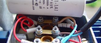
Often there is a need to start an asynchronous electric motor in normal domestic conditions, where the presence of a three-phase electrical network is not provided. In such a situation, you need to know how to connect the power unit to a 220V network. In order for the rotor to start rotating, an additional pulse action is required, for which a capacitor of the required capacity is usually included in the electrical circuit.
When using a capacitor, the speed does not change, but the power is noticeably reduced. Power losses can vary by up to fifty percent depending on the capacitor capacitance and the specific operating conditions of the electric motor. In addition, not all models of power units can operate in a single-phase power supply. Typically, this possibility is specified in the technical documentation for the product and is indicated on a tag attached to the case.
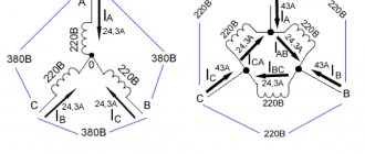
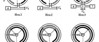
Of the large number of options now offered on the Internet for connecting an electric motor to a 220V network, two methods are considered standard - “star” and “triangle”. It is recommended that you first read the documentation for a particular electric motor and examine the nameplate with parameters on its body to find out what voltage the windings are designed for and how they can be connected.
In the delta circuit, one contact is connected through a capacitor to the winding, and the other two are output for connection to the power source. In this case, without load, the electric motor shaft will rotate freely at the desired speed, but if it is heavily loaded, the rotation will slow down significantly or stop completely. This problem can be solved if you additionally connect another capacitor to perform only one task - starting the electric motor, after which it discharges and turns off after a couple of seconds.
In order for the starting capacitor for the electric motor to be included in the circuit, a separate short-term start button is usually used. After the rotor spins, it opens the contacts, and the shaft continues to rotate by inertia with the support of the magnetic field of the winding. As such a switch, you can use a relay or a ready-made button with a contact group on a spring, which, when released, raises the contacts and is disconnected from the circuit. To avoid a short circuit between the turns, it is recommended to use a thermal relay that turns off the additional winding in the event of a critical temperature increase.
You can also use a centrifugal switch here, which opens the circuit when the permissible speed value is exceeded. The contact plate is pulled back under the influence of centrifugal forces and, when a given speed is reached, de-energizes the power plant or transmits a signal to an alternative control mechanism. There are several options for implementing rotation speed control and automatic overvoltage protection. The switch can be placed directly on the rotor shaft or on other parts of the structure, connected directly or through a gearbox. There are cases when both a centrifugal switch and a thermal relay are involved in one circuit.
To operate an electric motor connected using the “star” method, a single phase of 220 volts is passed through one of its windings, and a linear voltage of 380 volts is passed through the other two windings. The working capacitor is connected to the output ends of the windings, two of which are output for connection to a single-phase electrical network, and the free end is connected to the capacitor through the mains phase. It is worth noting that the “delta” connection is simpler and the power losses will be less than in the “star” circuit. Therefore, if possible, you should use the “triangle” one, but if the model of your electric motor does not support this connection method, then the only option left is the “star” one.
In our case, it is necessary not only to start the electric motor, but also to ensure the possibility of reverse movement. To do this, the power coming from the capacitor must switch between poles. This can be realized using two switches and one button without fixing the position. One switch will supply voltage to the electric motor power circuit, and the second switch should have a three-position design. In one position the power unit turns off, and in the second and third it changes the polarity of the windings so that the motor rotor rotates in different directions. The non-fixed button is designed to connect a second starter capacitor.
The procedure is as follows. The two outgoing wires from both capacitors are twisted together, and the start button is connected to the other two. The middle output from the three-position switch is connected to the twisted capacitor outputs, and the other two are routed to the motor terminals to supply power to it. Capacitors are also connected to the winding starting outputs, and the power button is mounted in the phase conductor gap. To put this entire structure into operation, voltage is first applied to the main switch and, using a three-position control element, the desired direction of movement of the power unit is indicated. Then the non-fixed start button is clamped and released after the rotor accelerates to operating speed. To start the electric motor in the other direction, you need to disconnect it from the power source and wait until the shaft stops completely. Only then switch the toggle switch to the reverse position.
Features of reversing starters
Such connection diagrams are used in the designs of elevators, cranes, and drilling machines. If you don’t go into too much detail, it may seem that the motor switching circuit using reverse is more complicated. But in reality it turns out that there is nothing complicated - another power unit and control have been added to the design.
The cost of such devices is slightly higher due to the use of more elements. Essentially, these are two electromagnetic starters combined into one housing. The operating principle of the circuit is specific; you will need to carefully consider all the nuances.
Safety precautions
During installation, adjustment and repair, safety regulations must be strictly observed..
In the case of working with an electric motor control circuit, to completely turn it off, you need to de-energize the power section and control circuits. Some electric motors can be powered by two independent power sources, so be sure to study the connection diagram. Make the necessary shutdowns and check with an indicator that there is no voltage not only on the power contacts, but also on the auxiliary contacts.
If capacitors are installed in the circuit, after turning off the power, you should give them time to discharge before touching conductive parts .