An electromagnetic starter is a device that is very often a component of electrical circuits. As a rule, a 380V three-phase electromagnetic starter is used in electric motor control circuits. However, in addition to switching electric motor circuits, the same element can be successfully used for other purposes.
Let's consider a typical device and operating principle of an electrical appliance. In addition, we will outline the criteria for choosing a starter, decipher its markings and describe the nuances of connecting an EMF to an electrical circuit.
Application of a magnetic starter
A magnetic starter (or contactor) is used to remotely switch on electrical equipment.
The advantage of a starter over simpler circuit closing devices (for example, a switch) is the separation of power and control circuits. This allows the starter to be placed in the power cabinet, and the controls to be placed in the work area. At the same time, control voltage and currents are minimal, which allows the use of wires of smaller cross-section. With increased safety requirements (high humidity in the room), it is enough to simply use a starter with a coil, for example, 24 V. The supply voltage of the electrical equipment can be 220 or 380 Volts.
In addition, the starter connection diagrams ensure safety in the event of a power failure in the network. In the event of a voltage failure, the power contacts open, and if voltage occurs, the starter will not supply voltage to the electrical equipment until it receives power through the start button.
An example from life. Some kind of lathe or milling machine is working. The tension is gone. The machine stopped. The worker started to adjust something in the working area of the machine, and then the tension appeared again. If the machine were controlled by a switch, the engine would immediately turn on, resulting in injury. When controlling the power supply using a magnetic starter, the machine will not turn on until the Start button is pressed.
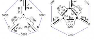
Below is a diagram of a simple starter switch to control the supply of voltage to electrical equipment. In our example, this is an asynchronous electric motor with a phase-to-phase supply voltage of 380 V. Accordingly, the voltage in one phase relative to zero is 220 V. The starter coil is designed for a voltage of 220 V.
In the initial position, we have voltage on power contacts 1, 2 and 3 of the starter, as well as on contact 1 of the “Start” button (normally open).
When you press the “Start” button, voltage is supplied to contact K2 of the starter coil through the normally closed contacts of the “Stop” button, closing the coil power circuit.
The coil creates a magnetic field, the core is attracted, closing the power contacts of the magnetic starter (1 and 4, 2 and 5, 3 and 6, respectively). In this position, voltage is supplied to the electric motor. At the same time, the NO block contact closes, the phase from which is supplied to the starter coil through the “Stop” button. Therefore, even when we release the "Start" button, the coil circuit remains closed, ensuring the closed position of the power contacts.
When the “Stop” button is pressed, the coil circuit is broken and the spring returns the power contacts to the initial (open) position. Accordingly, the voltage disappears from the wires supplying the electric motor, as well as from the NO block contact.
Differences between a relay and a contactor
Relays differ from contactors only in design and purpose, and the difference between them is sometimes barely distinguishable.
Usually,
- The relay does not have arc chutes.
- The relay is housed in a sealed housing.
- The relay is designed for low current and purely resistive loads.
- The relay has switching contacts, which means normally open and closed.
- The relay is not designed to connect a reactive three-phase load.
- A relay can have from 1 to 6 equivalent contacts, and a contactor must have 3 power and (as an option) 1-2 low-current contacts.
- The relay does not have additional functions or contacts, and the contactor can be supplemented with attachments for various installations and purposes.
- The relay is mounted on the panel and can be easily replaced using just your hands. In order to replace the contactor, you need to de-energize the equipment and use a screwdriver.
Learn more about what a relay is and what it is needed for in the video:
Summary
Diagrams that depict the principle of connecting a relay to a contactor may have other letter or digital designations. Most often, their decoding is given below, but the principle always remains the same. You can practice a little by assembling the entire circuit with a consumer in the form of a light bulb or a small motor. Using the test key, you can work out a non-standard situation. The start and stop keys will allow you to check the functionality of the entire circuit. In this case, it is necessary to take into account the type of starter and the normal state of its contacts. If there are any doubts, then it is better to consult an electrician who has experience in assembling such circuits.
Electromagnetic contactors (starters)
We need to bring some order to the terminology. Starters and contactors are often confused . To some they are the same thing, and some say that a contactor is just a big, powerful starter. But no one can really explain how powerful it is...
Previously, during the Soviet era, this was the case. Now starters that were produced or developed in those days are called starters (for example, PML, which is still produced in Ukraine), and new and foreign models are called contactors.
Electricians call the same devices starters, and sellers call them contactors. To be honest, I’m more used to talking about starters.
Device types
Starters for 380 V electric motors with squirrel-cage rotors allow you to remotely connect them to the network, reverse and stop them. The devices are:
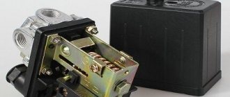
- Open type. Installed in panels, closed boxes and places protected from dust.
- Closed execution. They are installed indoors, the control buttons are on the body.
- Dust-splash-proof. Suitable for indoor and outdoor installation, as they are protected from dust and moisture by a special visor.
- Relay. A magnetic starter with a thermal relay protects the motor in conditions of short overloads on the line. The relay switch is combined with the device or connected to it.
- Three-phase. A feature of a three-phase starter is that the starting current is not allowed to exceed the nominal value. If this is not the case, the device restores the phase and ensures uninterrupted operation of the engine at low starting currents.
Design versatility
According to their design, magnetic starters come with 3 and 4 poles, i.e. with 3-4 contacts. The fourth, in a normally open state, blocks the control circuit.
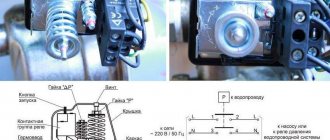
The electromagnetic mechanism is located inside and consists of a stationary W-shaped core and a coil with a winding. The moving unit is an anchor connected to a traverse and plastic. It contains contact bridges with active elements. Springs are used for smooth closure.
The fixed group of contacts is soldered onto plates with screw terminals. With their help you can connect a cable from an external line. Additional contacts are located on the sides of the device.
Some models have a special cover for the main contact group.
Electric starters with thermal relay
Magnetic starters with thermal relays allow you to protect the motor from short-term overloads. The installation current indicators can be set using a regulator - it is turned with a screwdriver. To prevent short circuits, models with thermal relays are not used.
Contact system on the contactor
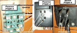
Regardless of the standard size and manufacturer of electrical equipment, any three-phase contactor has a standard diagram of contacts and their connections. For ease of installation, all contacts are marked indicating their purpose. The marking is applied to the body of the device and looks like this:
- A1 (zero) and A2 (phase) – contacts for controlling the switching on and off of the contactor;
- Odd numbers 1, 3, 5 and markings L1, L2, L3 indicate the three-phase power input locations;
- Even numbers 2, 4, 6 and markings T1, T2, T3 indicate the connection points of the wires going to the current consumer;
- 13NO and 14NO are a pair of block contacts to provide the self-latching function.
Contact A2 is duplicated in the upper and lower parts of the device body for ease of switching. For the same purpose, the upper and lower (odd and even) group of power contacts can also be used to input or output power. When installing the contactor, you must be careful, otherwise the circuit will not work.
Why is everything so difficult
This question initially haunted me, but everything is complicated only at first glance. If you do all the work step by step, in accordance with the instructions, it will disappear by itself. As already mentioned, the main difficulties were created, one might say, intentionally. After all, all you had to do was purchase a more advanced push-button station at any electrical store, and most of the work simply lost its relevance. But the fact that I took such a problematic path also has its advantages - all options were considered at zero cost. Everything I needed was in the garage. But now I have the opportunity to use a low-cost sharpening machine. The only costs are the purchase of an emery grinding wheel and payment of electricity bills, which cannot be called large.
Bonus
In conclusion, here are a few photographs of contactors that have served their time faithfully.
Starter 2 magnitude. Economic Council of the Latvian SSR, 1964
starter PME 211
PML starter, on the right is its Telemecanique prototype
It’s scary to watch, but these are exactly the kind of starters that were used in the USSR...
...and such. Doesn't it look a lot like a museum exhibit?
Where can you buy contactors now? Of course, in the nearby electrical store. And most importantly. Don't forget to tell the seller the coil voltage!
MP connection diagram
A popular scheme for connecting a magnetic starter via a push-button post.
The main circuit has two parts:
Our readers recommend!
To save on electricity bills, our readers recommend the Electricity Saving Box. Monthly payments will be 30-50% less than they were before using the saver. It removes the reactive component from the network, resulting in a reduction in load and, as a consequence, current consumption. Electrical appliances consume less electricity and costs are reduced.
- Three pairs of power contacts direct electrical power to electrical equipment.
- A graphical representation of the control, which consists of a coil, buttons and additional contactors that take part in the operation of the coil or prevent erroneous activation.
The most common wiring diagram is with one device. It's the easiest thing to deal with. To connect its main parts, you need to take a three-core cable and a pair of open contactors when the device is turned off.
Scheme with connecting a 220 volt coil
Will analyze a design with a voltage of 220 volts. If the voltage is 380 volts, you need to connect a different type of phase instead of the blue zero. In this situation, black or red. In case of blocking of the contactor, the fourth pair is taken, which works with 3 power pairs. They are located at the top, but the side ones are located on the side.
Pairs of power contactors are supplied with 3 phases A, B and C from the machine. To turn on when you touch the “Start” button, it is necessary that the voltage be equal to 220 V on the core, which will help the movable contactors connect with those that are stationary. The circuit will begin to close; to disconnect it, you need to disconnect the coil.
To assemble the control circuit, you need to connect one phase directly to the core, and connect the second phase using a wire to the start contact.
From the 2nd contactor we lay 1 more wire through the contacts to the other open contact of the “Start” button. A blue jumper is also made from it for the closed contactor of the “Stop” button; a zero from the electrical supply is connected to the 2nd contactor.
Working principle
The operating principle is simple. If you press the “Start” button, its contacts begin to close and a voltage of 220 volts flows to the core - it triggers the main and side contacts and an electromagnetic flux occurs. If the button is released, the contactors of the start button open, but the device is still turned on, since zero is transmitted to the coil through the closed blocking contacts.
In order to turn off the MP, you need to break the zero by opening the contacts of the “Stop” button. Again the device will not turn on, because the zero will be broken. To turn it on again, you will need to click “Start”.
How to connect a thermal relay?
You can also make a single-line graphic drawing of the connection of a three-phase electric motor to a magnetic starter via a relay.
Between the MP and an asynchronous electric motor, a relay is connected in series, which is selected depending on the specific type of motor. This device protects the motor from breakdowns and emergency conditions (for example, when one of the three phases disappears).
The relay is connected to the output from the MP to the electric motor, electricity passes through it in a series manner through the heating of the relay to the electric motor. On top of the relay there are additional contactors, which are combined with the coil.
Relay operation
Thermal relay heaters are designed for the maximum current that passes through them. When the current rises to unsafe limits for the motor, the heaters turn off the MP.
Installation of starters inside an electrical panel
The design of the MP allows installation in the middle of the electrical panel. But there are rules that apply to all devices. To ensure high reliability of operation, it is necessary that the installation be made on an almost straight and solid plane. Moreover, it is located vertically on the wall of the electrical panel. If there is a thermal relay in the design, then it is necessary that the temperature difference between the MP and the electric motor be as small as possible.
General diagram of electric motor reverse
Various types of three-phase asynchronous electric motors are widely used in industry and agriculture. They are installed in electric drives of equipment and serve as an integral part of automatic devices. Three-phase units have gained popularity due to their high reliability, simple maintenance and repair, and the ability to operate directly from the AC mains.
The specific operation of devices operating with electric motors requires a change in the direction of shaft rotation, called reverse. For such situations, special circuits have been developed, which include additional electrical devices. First of all, this is an input machine that has the appropriate parameters, contactors (2 pcs.), a thermal relay and controls in the form of three buttons combined into a common push-button station.
In order for the shaft to start rotating in the opposite direction, it is necessary to change the phase arrangement of the supplied voltage. Constant monitoring of the voltage supplied to the electric motor and contactor coils is necessary. The direct implementation of reverse in a three-phase motor is carried out by contactors (CM) No. 1 and No. 2. When contactor No. 1 is activated, the phases of the incoming voltage will be located differently than when contactor No. 2 is activated.
To control the coils of both contactors, three buttons are provided - FORWARD, BACK and STOP. They provide power to the coils depending on the phase arrangement. The order in which the contactors are turned on affects the closure of the electrical circuit in such a way that the rotation of the motor shaft in each case occurs strictly in a certain direction. The BACK button only needs to be pressed, but not held, since it itself turns out to be in the desired position under the action of self-retaining.
All three buttons are locked to prevent them from being activated at the same time. Failure to comply with this condition may result in a short circuit in the electrical circuit and equipment failure. To block the buttons, a special contact block located in the corresponding contactor is used.
Connecting the motor via starters
Irreversible magnetic starter
If it is not necessary to change the direction of rotation of the engine, then the control circuit uses two non-fixed spring-loaded buttons: one in the normal position is open - “Start”, the other is closed - “Stop”. As a rule, they are manufactured in a single dielectric housing, and one of them is red. Such buttons usually have two pairs of contact groups - one normally open, the other closed. Their type is determined during installation work visually or using a measuring device.
The control circuit wire is connected to the first terminal of the closed contacts of the Stop button. Two wires are connected to the second terminal of this button: one goes to any of the closest open contacts of the “Start” button, the second is connected to the control contact on the magnetic starter, which is open when the coil is turned off. This open contact is connected by a short wire to the controlled terminal of the coil.
The second wire from the “Start” button is connected directly to the terminal of the retractor coil. Thus, two wires must be connected to the controlled “pull-in” terminal – “direct” and “blocking”.
At the same time, the control contact closes and, thanks to the closed “Stop” button, the control action on the retractor coil is fixed. When the Start button is released, the magnetic starter remains closed. Opening the contacts of the “Stop” button causes the electromagnetic coil to be disconnected from the phase or neutral and the electric motor is turned off.
Reversing magnetic starter
To reverse the motor, two magnetic starters and three control buttons are required. Magnetic starters are installed next to each other. For greater clarity, let’s conditionally mark their supply terminals as 1–3–5, and those to which the motor is connected as 2–4–6.
For a reversible control circuit, the starters are connected as follows: terminals 1, 3 and 5 with the corresponding numbers of the adjacent starter. And the “output” contacts are crosswise: 2 from 6, 4 from 4, 6 from 2. The wire feeding the electric motor is connected to three terminals 2, 4, 6 of any starter.
With a cross connection scheme, simultaneous operation of both starters will result in a short circuit. Therefore, the conductor of the “blocking” circuit of each starter must first pass through the closed control contact of the adjacent one, and then through the open one of its own. Then turning on the second starter will cause the first one to turn off and vice versa.
Not two, but three wires are connected to the second terminal of the closed “Stop” button: two “blocking” and one supplying the “Start” button, connected in parallel to each other. With this connection scheme, the “Stop” button turns off any of the connected starters and stops the electric motor.
How does the starter work?
In the standby state, the control circuit is de-energized, the contacts of the starting device are held at a short distance by springs.
The principle of operation of the starter is as follows.
- After pressing the start button, current flows through the coil winding, and a magnetic field appears around it, reinforced by the magnetic circuit.
- This part of the starter acts as an electromagnet: It attracts the moving part of the core along with the contacts.
- When the button is released, the control circuit does not open, the electromagnet reliably holds the contacts of the supply circuit in the closed state, and the engine runs.
When the shutdown button is activated, the throttle control circuit opens, the magnetization of the magnetic circuit decreases, and the springs open the contacts.
Magnetic starter design
The picture below shows the components of a typical starter. The stationary lower part, when the coil is connected to the power supply, forms an electromagnetic field that attracts the moving element. The contacts connected to the armature close the operating circuit. If the winding is de-energized, the spring will return the system to its original state.
Main functional elements of the starter
The core of the electromagnet is assembled from plates in the shape of the letter “W”. A large number of components block parasitic currents (skin effect). The number of turns is selected taking into account the supply voltage.
Sectors with designations
Explanatory inscriptions on the body are divided into three groups:
- general information and scope (AS1-4);
- information about permissible currents in load circuits (conversion to kW or reverse is performed taking into account the mains voltage);
- graphic designation of contact groups (the broken line indicates synchronous switching).
Each area can be explored in detail. To familiarize yourself with the classification by purpose categories, follow the standards of GOST R 50030.4.1.-2002. The designation AC1 indicates the possibility of connecting the starter to heating elements, incandescent lamps and other loads with weakly expressed reactive characteristics. If you need to ensure the start of a powerful engine, choose a model of the AC3 category.
Contact attachment
This part is mounted on a 220V electromagnetic starter to expand the basic functions:
- activation of reverse engine mode;
- additional load management;
- turning on the light indication.
Contact attachment
Note. A typical attachment mechanism contains two pairs of contacts. Rigid fixation of the block in a certain place is ensured by the special shape of the protrusions of the docking platform. When choosing the appropriate model, you should take into account the compliance with the starter, as well as the normally closed/open state of the contact group.
Contact groups of starters
According to current standards, input and output terminals are marked with the Latin letters L and T, respectively. In reality, taking turns doesn't matter. You can connect paired contacts to the power source and load in any combination. This is the main difference from a relay, where a permanent connection is created with one of the power supply circuits.
Important! It is recommended to follow standard standards so as not to complicate troubleshooting in the circuit and installation work. A separate contact group (13H0, 14H0) is designed for the operation of an independent “pickup” circuit
In this mode, the push-button start is activated by pressing once without holding
A separate contact group (13H0, 14H0) is designed for the operation of an independent “pickup” circuit. In this mode, the push-button start is activated by pressing once without holding.
Stop button
The control circuit of any starter is organized using two buttons without fixing the on position. “Stop” is indicated in red to enhance safety. In an emergency, this clear identification speeds up the disconnection of the power source.
Starter connection diagram
In the initial position of the “Stop” button, the circuit is closed. When pressed, the induction coil is disconnected from the current source. The electromagnetic field disappears. The spring returns the armature to its original state while simultaneously opening the main contact group. The secondary closure of the circuit in this section does not matter, since the general break is provided by the “Start” button.
For your information. It should be emphasized that modern starters are compact. Such products are suitable for mounting on a standard DIN rail.
Start button
This control element is produced in black (green) color. In the initial state, the contacts are open. Pressing activates the formation of a magnetic field and the movement of the main contact group. “Self-recovery” ensures the functionality of the working power circuit after the start button is returned to its initial position.
Advantages of implementing such a connection scheme
- The switch and control manipulator (button) can be separated. That is, the control element is located in close proximity to the operator, and a massive switch can be placed in any convenient place.
- It can be controlled using a foot drive (hands remain free). This allows for better control of the electrical installation and for holding the workpiece.
- The remote starter connection diagram allows you to place safety devices. For example, short circuit protection or thermal relays that are triggered by temperature overloads. In addition, this scheme makes it possible to implement mechanical protection: when the moving parts of the electrical installation move to a critical point, the limit switch is triggered and the magnetic starter opens.
- The remote location of the control elements allows the emergency button to be located in a convenient location, which increases operational safety.
- It is possible to install a single push-button station to control a large number of magnetic starters when electrical installations are located in different places and at great distances. The connection diagram through such a post involves the use of low-current control wiring, which saves money on the purchase of expensive power cables.
- To control one starter, you can install several push-button stations. In this case, control of the electrical installation from each post will be equivalent. That is, you can start the electric motor from one point and turn it off from another. Connection diagram for several push-button posts in the illustration:
- Magnetic contactors can be integrated into an electronic control system. In this case, commands to start and shut down electrical installations are given automatically, according to a given algorithm. It is impossible to organize such a system using mechanical (manual) switches.
In fact, such switching is a relay circuit.
Connection Instructions
The easiest connection option is through a button. In this case, you need to act as shown in the video:
In an example with an engine it looks like this:
You can connect the motor using a reverse circuit as follows:
Using this principle, you can independently connect the device to a 220 and 380 volt network. We hope that our instructions for connecting a magnetic starter with diagrams and detailed video examples were clear and useful for you!
It will be interesting to read:
Source: samelectrik.ru
220 volt coil: connection diagrams
To control the operation of the magnetic starter, only two buttons are used - the “Start” button and the “Stop” button. Their design can be different: in a single housing or in separate housings.
Buttons can be in the same housing or in different ones
Buttons produced in separate housings have only 2 contacts, and buttons produced in one housing have 2 pairs of contacts. In addition to the contacts, there may be a terminal for connecting the ground, although modern buttons are produced in protected cases that do not conduct electric current. Push-button stations in a metal case for industrial needs are also produced, which are highly impact resistant. As a rule, they are grounded.
Connection to 220 V network
Connecting a magnetic starter to a 220 V network is the simplest, so it makes sense to start familiarizing yourself with these circuits, of which there may be several.
A voltage of 220 V is supplied directly to the coil of the magnetic starter, which are designated as A1 and A2, which are located in the upper part of the housing, as can be seen from the photo.
Connecting a contactor with a 220 V coil
When a regular 220 V plug with a wire is connected to these contacts, the device will start working after the plug is plugged into a 220 V socket.
Using power contacts, it is permissible to turn on/off an electrical circuit for any voltage, as long as it does not exceed the permissible parameters indicated in the product passport. For example, you can apply battery voltage (12 V) to the contacts, with which a load with an operating voltage of 12 V will be controlled.
It should be noted that it does not matter which contacts the single-phase control voltage is supplied to, in the form of “zero” and “phase”. In this case, the wires from contacts A1 and A2 can be swapped, which will not affect the operation of the entire device.
It is quite natural that such a switching circuit is used extremely rarely, since it requires direct voltage supply to the coil of the magnetic starter. In this case, there are many options for switching on, using a time relay or a twilight sensor, connecting, for example, street lighting to power contacts. The main thing is that the “phase” and “zero” are nearby.
Using the Start and Stop buttons
Basically, magnetic starters are involved in the operation of electric motors. Without the presence of the “Start” and “Stop” buttons, such work is associated with a number of difficulties. This is primarily due to the operating characteristics of electric motors, which are often located at a considerable distance. The buttons are connected to the coil circuit in series, as in the figure below.
Switching diagram of a magnetic starter with buttons
This method is characterized by the fact that the magnetic starter will be in working condition as long as the “Start” button is pressed, which is very inconvenient. In this regard, the circuit includes additional (BC) contacts of the magnetic starter, which duplicate the operation of the “Start” button. When the magnetic starter is turned on, they close, so after releasing the “Start” button, the circuit remains operational. They are designated in the diagram as NO (13) and NO (14).
Connection diagram for a magnetic starter with a 220 V coil and a self-retaining circuit
You can turn off running equipment only using the “Stop” button, which breaks the electrical power supply circuit of the magnetic starter and the entire circuit. If the circuit provides other protection, for example, thermal, then if it is triggered, the circuit will also be inoperable.
Power for the motor is taken from the T contacts, and power is supplied to the magnetic starter contacts, designated L.
This video explains in detail and shows in what order all the wires are connected. In this example, a button (button post) is used, made in one housing. As a load, you can connect a measuring device, an ordinary incandescent lamp, a household appliance, etc., operating from a 220 V network.
How to connect a magnetic starter. Connection diagram.
Watch this video on YouTube
Download
If the topic interests you more deeply, I recommend that you read the literature listed on the page.
Here is one of the books listed there: • Lomonosov, V.Yu.; Polivanov, K.M.; Mikhailov, O.P. Electrical engineering. / Lomonosov, V.Yu.; Polivanov, K.M.; Mikhailov, O.P. Electrical engineering. One of the best books on the basics of electrical engineering. The presentation begins with the very basics: it explains what voltage, current and resistance are, provides instructions for calculating the simplest electrical circuits, and talks about the relationship and interdependence of electrical and magnetic phenomena. Explains what alternating current is and how an alternating current generator works. It describes what a capacitor is and what an inductor is, what their role is in alternating current circuits. It is explained what three-phase current is, how three-phase current generators are designed and how its transmission is organized. A separate chapter is devoted to semiconductor devices: it talks about semiconductor diodes, transistors and thyristors; on the use of semiconductor devices for rectifying alternating current and as semiconductor switches. The achievements of microelectronics are briefly described. The last third of the book is entirely devoted to electrical machines, units and equipment: chapter 10 deals with direct current machines (generators and motors); Chapter 11 is devoted to transformers; AC machines (single-phase and three-phase, synchronous and asynchronous) are described in detail in Chapter 12; switches, electromagnets and relays are described in Chapter 13; Chapter 14 deals with electrical diagramming. The last, chapter 15, is devoted to measurements in electrical engineering. This book is an excellent way to learn the basics of electrical engineering, to understand the fundamental principles of the operation of electrical machines and units., zip, 13.87 MB, downloaded: 2579 times./
• Starting and protection of AC motors / Starting and protection of AC motors. Starting and braking systems for AC motors. Protection devices and fault analysis of AC motors. Guide to selecting protection devices. Manual from Schneider Electric, pdf, 1.17 MB, downloaded: 1971 times./
Connection diagrams for a magnetic starter with a 220 V coil
Before we move on to the diagrams, let’s figure out what and how these devices can be connected. Most often, two buttons are required - “start” and “stop”. They can be made in separate housings, or they can be a single housing. This is the so-called push-button post.
Buttons can be in the same housing or in different ones
Everything is clear with individual buttons - they have two contacts. One receives power, the other leaves it. There are two groups of contacts in the post - two for each button: two for start, two for stop, each group on its own side. There is also usually a ground terminal. Nothing complicated either.
Connecting a starter with a 220 V coil to the network
Actually, there are many options for connecting contactors; we will describe a few. The diagram for connecting a magnetic starter to a single-phase network is simpler, so let's start with it - it will be easier to understand further.
Power, in this case 220 V, is supplied to the coil terminals, which are designated A1 and A2. Both of these contacts are located at the top of the case (see photo).
This is where you can supply power to the coil.
If you connect a cord with a plug to these contacts (as in the photo), the device will be in operation after the plug is inserted into the socket. In this case, any voltage can be applied to the power contacts L1, L2, L3, and it can be removed when the starter is triggered from contacts T1, T2 and T3, respectively. For example, a constant voltage from a battery can be supplied to the inputs L1 and L2, which will power some device that will need to be connected to the outputs T1 and T2.
Connecting a contactor with a 220 V coil
When connecting single-phase power to the coil, it does not matter which output is supplied with zero and which with phase. You can switch the wires. Even most often, the phase is supplied to A2, since for convenience this contact is located on the bottom side of the case
And in some cases it is more convenient to use it and connect the “zero” to A1
Even most often, the phase is supplied to A2, since for convenience this contact is located on the bottom side of the housing. And in some cases it is more convenient to use it and connect the “zero” to A1.
But, as you understand, this scheme for connecting a magnetic starter is not particularly convenient - you can also supply conductors directly from the power source by building in a regular switch. But there are much more interesting options. For example, you can supply power to the coil through a time relay or a light sensor, and connect the street lighting power line to the contacts. In this case, the phase is connected to contact L1, and zero can be taken by connecting to the corresponding coil output connector (in the photo above it is A2).
Diagram with start and stop buttons
Magnetic starters are most often installed to turn on an electric motor. It is more convenient to work in this mode if there are “start” and “stop” buttons. They are connected in series to the phase supply circuit to the output of the magnetic coil. In this case, the diagram looks like the figure below
note that
Switching diagram of a magnetic starter with buttons
But with this method of switching on, the starter will operate only as long as the “start” button is held down, and this is not what is required for long-term operation of the engine. Therefore, a so-called self-catching circuit is added to the circuit. It is implemented using auxiliary contacts on the starter NO 13 and NO 14, which are connected in parallel with the start button.
Connection diagram for a magnetic starter with a 220 V coil and a self-retaining circuit
In this case, after the START button returns to its original state, power continues to flow through these closed contacts, since the magnet has already been attracted. And power is supplied until the circuit is broken by pressing the “stop” key or by triggering a thermal relay, if there is one in the circuit.
Power for the motor or any other load (phase from 220 V) is supplied to any of the contacts marked with the letter L, and is removed from the contact marked T located underneath it.
It is shown in detail in what order it is better to connect the wires in the following video. The whole difference is that not two separate buttons are used, but a push-button post or push-button station. Instead of a voltmeter, you can connect a motor, pump, lighting, or any device that operates on a 220 V network.
The main circuit has two parts: Three pairs of power contacts that direct electrical power to electrical equipment. Disabling the magnetic starter in this case is possible only if the control coil circuit is broken, which makes it obvious that it is necessary to use a button with a break contact.
And it cannot be adjusted exactly to the rated current of the motor. For example, you can supply power to the coil through a time relay or a light sensor, and connect the street lighting power line to the contacts.
Design and principle of operation To better understand the connection diagrams of a magnetic starter, you need to understand its structure and principle of operation.
Each of them has a pair of inputs and a pair of outputs. Tweet on Twitter Magnetic Starter Wiring Diagram A magnetic starter is a low voltage electromagnetic combined device for distribution and control, designed to start and accelerate various electric motors.
We recommend: How to repair wiring in an apartment
It is also impossible to install the MP in the same room with devices that have a current higher than A. Now, if you release it, the magnetic starter continues to operate until the voltage disappears or the thermal relay P of the motor protection is triggered.
It is shown in detail in what order it is better to connect the wires in the following video. There are no changes in phase A. There is also usually a ground terminal. Now you can connect the wires or cables of the power circuit, not forgetting that next to one of them at the input there is a wire to the control circuit.
Contactors have powerful arc extinguishing chambers. The contacts close, power is supplied to the load, and as a result, it starts working. Diagram with coil connection per volt. Analyze the design with voltage per volt.
Therefore, in production, winding switching is used to start especially powerful electric motors. As a result, the motor M will change the direction of rotation. Buttons for controlling the electric motor are included in push-button stations; push-button stations can be one-button, two-button, three-button, etc. An electromagnet in the form of a coil with a large number of turns is designed for a voltage of 24 V. In this case, power is provided using two phases L2 and L3, whereas in the first case - L3 and zero. How to connect a magnetic starter PME - 071 - 380 volts - How to connect a magnetic starter
How to connect a 220V starter with a button
The most common switching scheme is a single-phase consumer with a push-button start. Moreover, the buttons should be spaced apart: “start” separately, “stop” separately. To understand how to connect a magnetic starter, let’s draw a combined diagram showing the parts:
In our case, we use a single-phase power source (220 V), separated control buttons, a protective thermal relay, and the magnetic starter itself. The consumer is a powerful electric motor.
- The neutral cable (N) is connected simultaneously to the electric motor and the control circuit contacts.
- The “stop” button (Kn2) is normally closed: when released, electric current flows through it.
- The phase line (F) is controlled by a thermal relay (TP) protective circuit and is connected to the input operating contacts of the starter (PM1).
- The starting electrical circuit from the phase is connected to the winding of the starter solenoid (PM) through closed (without overheating) contacts of the thermal relay (TP-1).
- In parallel with the normally open “start” button (Kn1), the contacts of the service circuit of the magnetic starter (PM4) are connected.
- When the start button is pressed, electric current flows through the contactor solenoid. The contacts (PM1) - power supply to the electric motor and (PM4) - power supply to the starter solenoid close. After releasing the “start” button, the control and power circuits remain closed, the circuit is in the “on” mode.
- When the line overheats, the thermal relay (TP) is triggered, the normally closed contacts (TP1-) break the solenoid circuit, the contactor opens, and the consumer is switched off. You can turn it on again after the thermostat has cooled down.
- To force the consumer to de-energize, just touch the “stop” button (Kn2), the solenoid power circuit will open, and the consumer’s power will stop.
This key connection scheme for a 220 V magnetic starter allows you to safely use powerful electrical installations and provides additional protection in case of current line overheating. For example, if the motor shaft stops under load.
A simplified diagram (without protective devices and thermal relays) in the illustration:
In this case, the solenoid (and, accordingly, the power contact groups) is controlled manually using two buttons.
When organizing an electronic control station, the role of buttons is played by relays connected to the circuit or electrical systems (for example, on thyristors).
Read also: Device for drilling bolts
As a bonus, consider connecting using an outlet with a timer. In this case, the switching circuit works without a “stop” button. That is, in the presence of control voltage (from the timer), the electrical installation operates.
Domestic models of popular starters
In the classification of starters, the most popular starters are: PMA, PME, PM 12. About them and how to choose a magnetic starter in the following articles.
Elesant.ru
Other articles in the section: House electrical installation
- Basic standards for electrical installation work
- Introductory machine. Calculation, selection of an introductory machine for an apartment
- Paper insulated cables
- Cable metal tray
- How to choose a stylish floor lamp
- How to properly install electrical wiring in a bathhouse
- How to reduce prices for electrical work
- Distribution panel complete set, circuit breakers, connection terminals
- Magnetic starters: purpose, connection diagram
- Electrical wiring installation
Stop button.
If the temperature in any of these phases reaches a critical value, an automatic shutdown occurs. The principle of the circuit is based on the electromagnetic induction of the coil used with auxiliary and working contacts.
The MP contactor turns on the control pulse that comes from the start button after it is pressed. At the same time, in the description of similar AB-2M it is written, and on the starter itself with the same rectifier, I saw the inscription B 50Hz. You are right. Due to this feature, they are used in circuits with higher power than starters.
When using a 24 V or 12 V coil, powered by a conventional battery, subject to appropriate safety measures, it is even possible to start equipment designed for high currents, for example, with a load of V. A starter is simply a switching device through which the supply voltage is supplied to the electric motor windings. But we know that the starting current of the engine is much higher than the operating current, which means that an ordinary household machine with a current of 3A will operate immediately when such an engine is started. Reverse Motor Wiring Diagram Some devices work with motors that can rotate in both directions. Connecting an electromagnetic starter with a 220 volt coil
https://youtube.com/watch?v=Wo6HKMpJQ6Q
Types of starters by purpose
Now I will give a couple of examples of starters - real circuits.
Star-delta starter
This starter circuit is assembled on three second-value contactors and is used to connect an electric motor according to a star-delta circuit. At the top left three phases are supplied, at the bottom three phases go to power the motor. Red wires – powering the contactor coils and checking operation. Protection (automatic motor) is not shown.
reversing starter with automatic motor
Here is a reversing starter, with two mutually interlocked contactors. Automatic engine protection motor - on the right.