Usually we see this device in the form of a neat box with two buttons: “start” and “stop”. If you remove the top cover, inside you will find a switch of a rather complex design that can perform several tasks (both in turn and simultaneously).
This is an electromagnetic starter. The question arises: why create complex electrical devices if you just need to close two (or more) contacts? There are buttons with fixation, lever switches, circuit breakers, switches. Let's consider a typical application of a magnetic starter: turning on a powerful electrical installation (for example, an asynchronous electric motor).
- A powerful contact group with arc extinguishers is required; accordingly, a lot of force is required to close the contacts. A manual drive will be quite cumbersome (using a classic switch does not always fit into the aesthetics of the workplace).
- It is difficult to quickly change the operating mode with manual switches (for example, changing the direction of rotation of the motor). The magnetic starter device allows you to assemble such a connection diagram.
- Organization of protection. Any machine with an emergency shutdown is not designed to be turned on multiple times. The purpose (albeit not the main one) of a magnetic starter is not only to repeatedly switch, but also to disconnect the power circuit in case of overloads and short circuits. At the same time, it has an undeniable advantage over other switches. The shutdown is irreversible: that is, after an emergency opening of the contacts, or a momentary loss of power, the operating contacts do not return to the default “ON” position. The principle of operation of the magnetic starter implies only forced restart.
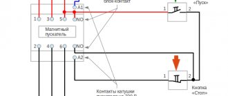
Connection diagram of a push-button post and its operating principle
To connect a contactor or starter to control the light from two buttons (like any other system), we need:
- Push button post.
- A contactor or starter with the number of power contacts (poles) equal to the number of phases.
- Three strands of wire.
Connecting the contactor to the push-button post is done as follows:
The voltage of the device coil is determined (usually 220 or 380). The phase is taken from the power contacts (if the coil is 380, we take two opposite phases, if 220, we take phase and zero). Connect the phase wire to the normally closed contacts of the “STOP” button. The “START” button is connected in series with the “STOP” button. From a normally open pair of block contacts of a contactor or starter, lay two wires to the push-button post (from two contacts, respectively) and connect them to the “START”, so that its normally open pair and open block contacts are connected in parallel. In this case, the contacts to which the phase has now arrived will be conventionally called “1”, and to which the phase will be supplied after pressing the key and the block contacts are triggered “2”
Important note: by this step we already have an incoming phase through the normally closed “STOP” to the open “START”; the block contacts of the starter or contactor are also connected to the same circuit. We connect the coil output to block contact “2” (often on modern contactors they are designated as A1 and A2).
We connect the second terminal of the coil to zero if it is designed for a voltage of 220V or to another phase - if for 380V, respectively
We connect the power supply wires; the phase to the push-button station is usually taken from these same terminals. Connect the wires from the lighting system (the lighting installations themselves).
Everything that is described above, but in graphical form, you can see in this diagram.
In the figure there is an additional power-on indication - a light bulb in the chain of control buttons and block contacts. It will allow you to understand whether the contactor and external light are turned on, without leaving the push-button post.
Note
: the light control scheme using starters is also good because you can easily organize light control from two or more places - you just need to add push-button posts in parallel to the existing ones.
Why do you need a contactor?
Just like the subtypes, the original contactor is needed to control the electrical circuit. But it has several operating features:
the ability to fully automate the switching on and off of the circuit;
high speed of operation, allowing the circuit to be closed and opened up to several thousand times per hour.
Thanks to these features, contactors are used in areas where electrical circuits need to be activated regularly and frequently. Doing this manually is not only inconvenient, but even ineffective. So it is better to entrust the work to an automated system.
Connecting the motor via starters
Irreversible magnetic starter
If it is not necessary to change the direction of rotation of the engine, then the control circuit uses two non-fixed spring-loaded buttons: one in the normal position is open - “Start”, the other is closed - “Stop”. As a rule, they are manufactured in a single dielectric housing, and one of them is red. Such buttons usually have two pairs of contact groups - one normally open, the other closed. Their type is determined during installation work visually or using a measuring device.
The control circuit wire is connected to the first terminal of the closed contacts of the Stop button. Two wires are connected to the second terminal of this button: one goes to any of the closest open contacts of the “Start” button, the second is connected to the control contact on the magnetic starter, which is open when the coil is turned off. This open contact is connected by a short wire to the controlled terminal of the coil.
The second wire from the “Start” button is connected directly to the terminal of the retractor coil. Thus, two wires must be connected to the controlled “pull-in” terminal – “direct” and “blocking”.
At the same time, the control contact closes and, thanks to the closed “Stop” button, the control action on the retractor coil is fixed. When the Start button is released, the magnetic starter remains closed. Opening the contacts of the “Stop” button causes the electromagnetic coil to be disconnected from the phase or neutral and the electric motor is turned off.
Reversing magnetic starter
To reverse the motor, two magnetic starters and three control buttons are required. Magnetic starters are installed next to each other. For greater clarity, let’s conditionally mark their supply terminals as 1–3–5, and those to which the motor is connected as 2–4–6.
For a reversible control circuit, the starters are connected as follows: terminals 1, 3 and 5 with the corresponding numbers of the adjacent starter. And the “output” contacts are crosswise: 2 from 6, 4 from 4, 6 from 2. The wire feeding the electric motor is connected to three terminals 2, 4, 6 of any starter.
With a cross connection scheme, simultaneous operation of both starters will result in a short circuit. Therefore, the conductor of the “blocking” circuit of each starter must first pass through the closed control contact of the adjacent one, and then through the open one of its own. Then turning on the second starter will cause the first one to turn off and vice versa.
Not two, but three wires are connected to the second terminal of the closed “Stop” button: two “blocking” and one supplying the “Start” button, connected in parallel to each other. With this connection scheme, the “Stop” button turns off any of the connected starters and stops the electric motor.
Characteristics of contactors
To choose the right device for your needs, you need to know what characteristics this type of device has and how they differ. Typically, electromagnetic contactors have the following important characteristics:
- Limit and rated voltage;
- Correlation of work with various circuit breakers (protecting against short circuits);
- Parameters and types of acceleration regulators of automatic circuit breakers;
- Characteristics and type of resistances;
- Type and nature of relays and releases and other elements in its composition.
Connecting the starter according to the star-delta scheme
Connecting the starter according to the star-delta circuit.
Switching the motor from star to delta is used to protect electrical circuits from overloads. Mostly powerful three-phase asynchronous motors from 30-50 kW and high-speed ~3000 rpm, sometimes 1500 rpm, are switched from star to delta.
If the motor is connected in a star, then a voltage of 220 Volts is supplied to each of its windings, and if the motor is connected in a triangle, then a voltage of 380 Volts is supplied to each of its windings. Here Ohm's law I=U/R comes into play: the higher the voltage, the higher the current, but the resistance does not change.
Simply put, when connected to a delta (380), the current will be higher than when connected to a star (220).
When the electric motor accelerates and reaches full speed, the picture completely changes. The fact is that the engine has power that does not depend on whether it is connected to a star or a triangle. Engine power depends largely on the iron and wire cross-section. Another law of electrical engineering applies here: W=I*U.
Power is equal to current times voltage, meaning the higher the voltage, the lower the current. When connected to a delta (380), the current will be lower than to a star (220). In the motor, the ends of the windings are brought out to the “terminal block” in such a way that, depending on how you place the jumpers, you get a star or delta connection. This diagram is usually drawn on the lid. In order to switch from star to delta, we will use contacts instead of jumpers.
Diagram for connecting a three-phase motor to a single-phase network with reverse and a button for connecting a starting capacitor.
Connection diagram for a three-phase asynchronous motor, in the starting position of which the stator windings are connected by a star, and in the operating position by a triangle.
There are six ends suitable for the engine. The KM magnetic starter is used to turn the motor on and off. The contacts of the magnetic starter KM1 work as jumpers to turn on the asynchronous motor in a triangle
Please note that the wires from the motor terminal block must be connected in the same order as in the motor itself. The main thing is not to confuse
The KM2 magnetic starter connects jumpers for star connection to one half of the terminal block, and voltage is supplied to the other half.
When you press the “START” button, power is supplied to the KM magnetic starter. It is triggered and voltage is supplied to it through the block contact. The button can now be released. Next, voltage is applied to the radio, it counts down the set time. Also, voltage is supplied through the closed contact of the time relay to the magnetic starter KM2, and the engine starts in the “star”.
After the set time, the RT time relay is activated. Magnetic starter P3 is turned off. The voltage is supplied through the time relay contact to the normally closed (closed in the off position) block contact of the magnetic starter KM2, and from there to the coil of the magnetic starter KM1. And the electric motor is switched into a triangle.
Switching diagram of an irreversible starter.
The KM2 starter should also be connected through a normally closed contact block of the KM1 starter to protect against simultaneous activation of the starters.
It is better to take double magnetic starters KM1 and KM2 with a mechanical lock for simultaneous activation.
The “STOP” button turns off the circuit.
The scheme consists of:
- Circuit breaker.
- Three magnetic starters KM, KM1, KM2.
- Start-stop button; - Current transformers TT1, TT2; - Current relay RT; - Time relay RV.
- BKM, BKM1, BKM2 are block contacts of their starter.
Where are contactors used?
What are contactors used for? The areas of application of these devices are varied:
- utilities: management of lighting, elevators, ventilation and heat and water supply systems;
- in industry and construction, contactors are found in almost all electrical devices;
- for electric transport: in trams and trolleybuses, these devices are responsible for the operation of the traction motor;
- in domestic conditions, with the help of contactors, they automate the operation of intra-house electrical networks.
Depending on the functions, there are also highly specialized contactors designed to work, for example, only with motors or construction electrical equipment. Before you buy a device of this type, you need to decide exactly where and under what conditions it will work.
Connection diagrams for a magnetic starter with a 220 V coil
Before we move on to the diagrams, let’s figure out what and how these devices can be connected. Most often, two buttons are required - “start” and “stop”. They can be made in separate housings, or they can be a single housing. This is the so-called push-button post.
Buttons can be in the same housing or in different ones
Everything is clear with individual buttons - they have two contacts. One receives power, the other leaves it. There are two groups of contacts in the post - two for each button: two for start, two for stop, each group on its own side. There is also usually a ground terminal. Nothing complicated either.
Connecting a starter with a 220 V coil to the network
Actually, there are many options for connecting contactors; we will describe a few. The diagram for connecting a magnetic starter to a single-phase network is simpler, so let's start with it - it will be easier to understand further.
Power, in this case 220 V, is supplied to the coil terminals, which are designated A1 and A2. Both of these contacts are located at the top of the case (see photo).
This is where you can supply power to the coil.
If you connect a cord with a plug to these contacts (as in the photo), the device will be in operation after the plug is inserted into the socket. In this case, any voltage can be applied to the power contacts L1, L2, L3, and it can be removed when the starter is triggered from contacts T1, T2 and T3, respectively. For example, a constant voltage from a battery can be supplied to the inputs L1 and L2, which will power some device that will need to be connected to the outputs T1 and T2.
Connecting a contactor with a 220 V coil
When connecting single-phase power to the coil, it does not matter which output is supplied with zero and which with phase. You can switch the wires
Even most often, the phase is supplied to A2, since for convenience this contact is located on the bottom side of the housing. And in some cases it is more convenient to use it and connect the “zero” to A1.
But, as you understand, this scheme for connecting a magnetic starter is not particularly convenient - you can also supply conductors directly from the power source by building in a regular switch. But there are much more interesting options. For example, you can supply power to the coil through a time relay or a light sensor, and connect the street lighting power line to the contacts. In this case, the phase is connected to contact L1, and zero can be taken by connecting to the corresponding coil output connector (in the photo above it is A2).
Diagram with start and stop buttons
Magnetic starters are most often installed to turn on an electric motor. It is more convenient to work in this mode if there are “start” and “stop” buttons. They are connected in series to the phase supply circuit to the output of the magnetic coil. In this case, the diagram looks like the figure below
note that
Switching diagram of a magnetic starter with buttons
But with this method of switching on, the starter will operate only as long as the “start” button is held down, and this is not what is required for long-term operation of the engine. Therefore, a so-called self-catching circuit is added to the circuit. It is implemented using auxiliary contacts on the starter NO 13 and NO 14, which are connected in parallel with the start button.
Connection diagram for a magnetic starter with a 220 V coil and a self-retaining circuit
In this case, after the START button returns to its original state, power continues to flow through these closed contacts, since the magnet has already been attracted. And power is supplied until the circuit is broken by pressing the “stop” key or by triggering a thermal relay, if there is one in the circuit.
Power for the motor or any other load (phase from 220 V) is supplied to any of the contacts marked with the letter L, and is removed from the contact marked T located underneath it.
It is shown in detail in what order it is better to connect the wires in the following video. The whole difference is that not two separate buttons are used, but a push-button post or push-button station. Instead of a voltmeter, you can connect a motor, pump, lighting, or any device that operates on a 220 V network.
How to choose a contactor
The larger the device, the more powerful the load it can handle. It is important to pay attention to the fact that the coil voltage is equal to the control voltage, and the contacts can withstand the load when connecting all consumers. There are 3 classes of switching wear resistance of such devices (A, B and C). It is better to choose a product with a small supply of this parameter.
Before selecting a contactor, it is important to have an understanding of the operating conditions. Based on this, the optimal degree of protection is selected. For example, if the equipment will be located in an electrical cabinet, then it is enough to purchase a model with a degree of protection IP20. For dusty rooms or objects with high humidity, you should choose more protected enclosures (IP45 or 65). A protection module equipped with a thermal relay can save you from overloads.
220 volt coil: connection diagrams
To control the operation of the magnetic starter, only two buttons are used - the “Start” button and the “Stop” button. Their design can be different: in a single housing or in separate housings.
Buttons can be in the same housing or in different ones
Buttons produced in separate housings have only 2 contacts, and buttons produced in one housing have 2 pairs of contacts. In addition to the contacts, there may be a terminal for connecting the ground, although modern buttons are produced in protected cases that do not conduct electric current. Push-button stations in a metal case for industrial needs are also produced, which are highly impact resistant. As a rule, they are grounded.
Connection to 220 V network
Connecting a magnetic starter to a 220 V network is the simplest, so it makes sense to start familiarizing yourself with these circuits, of which there may be several.
A voltage of 220 V is supplied directly to the coil of the magnetic starter, which are designated as A1 and A2, which are located in the upper part of the housing, as can be seen from the photo.
Connecting a contactor with a 220 V coil
When a regular 220 V plug with a wire is connected to these contacts, the device will start working after the plug is plugged into a 220 V socket.
Using power contacts, it is permissible to turn on/off an electrical circuit for any voltage, as long as it does not exceed the permissible parameters indicated in the product passport. For example, you can apply battery voltage (12 V) to the contacts, with which a load with an operating voltage of 12 V will be controlled.
It should be noted that it does not matter which contacts the single-phase control voltage is supplied to, in the form of “zero” and “phase”. In this case, the wires from contacts A1 and A2 can be swapped, which will not affect the operation of the entire device.
It is quite natural that such a switching circuit is used extremely rarely, since it requires direct voltage supply to the coil of the magnetic starter. In this case, there are many options for switching on, using a time relay or a twilight sensor, connecting, for example, street lighting to power contacts. The main thing is that the “phase” and “zero” are nearby.
Using the Start and Stop buttons
Basically, magnetic starters are involved in the operation of electric motors. Without the presence of the “Start” and “Stop” buttons, such work is associated with a number of difficulties. This is primarily due to the operating characteristics of electric motors, which are often located at a considerable distance. The buttons are connected to the coil circuit in series, as in the figure below.
Switching diagram of a magnetic starter with buttons
This method is characterized by the fact that the magnetic starter will be in working condition as long as the “Start” button is pressed, which is very inconvenient. In this regard, the circuit includes additional (BC) contacts of the magnetic starter, which duplicate the operation of the “Start” button. When the magnetic starter is turned on, they close, so after releasing the “Start” button, the circuit remains operational. They are designated in the diagram as NO (13) and NO (14).
Connection diagram for a magnetic starter with a 220 V coil and a self-retaining circuit
You can turn off running equipment only using the “Stop” button, which breaks the electrical power supply circuit of the magnetic starter and the entire circuit. If the circuit provides other protection, for example, thermal, then if it is triggered, the circuit will also be inoperable.
Power for the motor is taken from the T contacts, and power is supplied to the magnetic starter contacts, designated L.
This video explains in detail and shows in what order all the wires are connected. In this example, a button (button post) is used, made in one housing. As a load, you can connect a measuring device, an ordinary incandescent lamp, a household appliance, etc., operating from a 220 V network.
How to connect a magnetic starter. Connection diagram.
Watch this video on YouTube
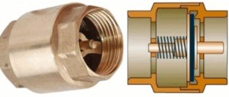
EMF design features
The design of an electromagnetic starter (EMF) is not highly complex. But this factor does not in any way reduce the reliability of the device.
How does this device work?
The reliability criterion is, for the most part, established by the correct connection of the circuits and the precise selection of the load.
If these criteria are met, the device will operate flawlessly for a long time in most cases.
The classic version includes the following elements:
- The body is dismountable in two halves.
- Inductor.
- Magnetic core.
- Switching mobile chassis.
- Group of main contacts.
- Group of auxiliary contacts.
The element of the magnetic starter, responsible for organizing the switching of the power circuit, is a movable chassis combined with one part (moving) of the magnetic circuit.
The chassis itself is made of dielectric material, and metal (brass) plates are used as closing contacts. At the ends of the plates there are contact patches made of refractory metals, usually a silver alloy.
The fixed part of the magnetic circuit is rigidly mounted inside the second half of the electromagnetic starter housing. An inductance coil is placed on this part of the magnetic circuit and a return spring is installed.
The second part of the device body is also equipped with contacts for power and auxiliary groups. These contacts are rigidly fixed to the housing using screws.
The design of a standard magnetic starter involves combining two halves of the housing, as a result of which the two halves of the W-shaped magnetic circuit are also combined into a single structure.
At the same time, due to the return spring, a small gap remains between the halves of the magnetic circuit; the main contact groups in this position remain broken.
Operating principle of EMF
The operating principle of the device is based on the effect of electromagnetic induction. If there is no voltage on the coil located inside the starter, the magnetic circuit remains in the “with gap” position, the main contacts are broken.
When an electric current is passed through the coil, under the influence of a magnetic field, the second (moving) part of the magnetic circuit overcomes the force of the spring and is attracted to the first (fixed) part.
Accordingly, the main contact groups of the starter are closed by the plates of the movable chassis.
The reverse process is obvious - when the voltage is removed from the terminals of the inductor, the magnetic field ceases to operate, and under the force of the return spring, the movable chassis and the second part of the magnetic circuit are repelled. Accordingly, the magnetic starter returns to the contact-break state.
It should be noted that based on the configuration of the electrical device, the circuit of contact groups can have a very different structure. Especially regarding auxiliary contacts, which may be in a closed or open state in contrast to the state of the main contacts of the device.
A feature of modern designs of magnetic starters is the modernization of the inductor control circuit.
If the design of previous “outdated” devices involved direct supply of voltage to a coil taken from one of the phases, electronic circuits are now increasingly used.
For example, known products are equipped with an electronic circuit for stabilizing the voltage supplied to the terminal of the inductor coil of the magnetic starter.
Controlling the coil through an electronic circuit is characterized by the fact that the alternating voltage is first rectified and then a pulse signal is generated. This approach provides increased service life and improved stability of operation.
Starter control buttons
In general, you will need two buttons: one to turn on and one to turn off.
Please note that they use contacts with different purposes to control the starter. The “Stop” button is normally closed, that is, if the button is not pressed, the group of contacts is closed, and opens when the button is activated
The Start button is the opposite.
Manufacturers usually provide their products with symbols that make it possible to determine the purpose of a particular contact group. The stop button is usually painted red. The launcher color is traditionally black, but green is welcome, which corresponds to the “On” or “Turn on” signal. Such buttons are mainly used on cabinet doors and machine control panels.
For remote control, push-button stations are used, containing two buttons in one housing. The station is connected to the starter installation location using a control cable. It must have at least three cores, the cross-section of which may be small.
The simplest working circuit of a starter with a thermal relay
Preparing for connection
The connection diagram of the contactor is directly dependent on the equipment with which it will operate. In addition to engines, all kinds of fans and pumps, compressors, heating elements and other devices act in this capacity. It is necessary to take into account the specifics of the contactor apparatus, which, in comparison with automatic machines, is not equipped with any protection. Therefore, when developing networks used to connect equipment, factors affecting current performance and the degree of heating must be taken into account.
Additionally, it is necessary to consider protective measures in case of short circuits and loads many times greater than the contactor rating. This problem can be solved by installing fuses. This category includes a circuit breaker, as well as thermal relays that protect equipment from prolonged excess current ratings and overheating.
Before connecting, you need to find out which contacts are the main ones and which of them perform an auxiliary function. Each switching coil has its own rated currents and voltages indicated in the marking.
Certain features exist when installing and connecting a modular device, which is a type of ordinary switching device. Such a contactor in the diagram is used to switch on and off at a distance equipment installed in distribution panels, including ABB. It follows that when a modular contactor is put into operation, power is supplied to a certain group of machines connected to certain circuits. Devices of this type operate successfully with all types of currents.
Stop button.
If the temperature in any of these phases reaches a critical value, an automatic shutdown occurs. The principle of the circuit is based on the electromagnetic induction of the coil used with auxiliary and working contacts.
The MP contactor turns on the control pulse that comes from the start button after it is pressed. At the same time, in the description of similar AB-2M it is written, and on the starter itself with the same rectifier, I saw the inscription B 50Hz. You are right. Due to this feature, they are used in circuits with higher power than starters.
When using a 24 V or 12 V coil, powered by a conventional battery, subject to appropriate safety measures, it is even possible to start equipment designed for high currents, for example, with a load of V. A starter is simply a switching device through which the supply voltage is supplied to the electric motor windings. But we know that the starting current of the engine is much higher than the operating current, which means that an ordinary household machine with a current of 3A will operate immediately when such an engine is started. Reverse Motor Wiring Diagram Some devices work with motors that can rotate in both directions. Connecting an electromagnetic starter with a 220 volt coil
https://youtube.com/watch?v=Wo6HKMpJQ6Q
Conclusions and useful video on the topic
A complete informative breakdown of the magnetic starter through a video recorded by a well-known trading company of electronic components.
The author of the video reveals in detail and in an accessible form the essence of the switching device:
Switching devices, similar to an electromagnetic starter for three-phase networks, are used quite often in the industrial, economic and domestic spheres. Therefore, it is useful to study information regarding such devices in a timely manner - how to work with them, how to connect them, how to determine for installation, etc.
Do you have anything to add, or do you have questions about choosing and connecting an electromagnetic starter? You can leave comments on the publication, participate in discussions and share your own experience of using such devices. The contact form is located in the lower block.
220 V starter control circuit
One wise man said: there are 44 schemes for connecting buttons to a magnetic starter, of which 3 work, and the rest do not. But there is only one correct one. Let's talk about it (see diagram below). It is better to leave connecting the power circuits for later. This will make it easier to access the coil screws, which are always covered by the main circuit wires. To power the control circuits, we use one of the phase contacts, from which we send a conductor to one of the terminals of the “Stop” button.
This can be either a conductor or a cable core.
To do this, a jumper is placed between the buttons, and a cable core to the starter is added to one of them at the point where it is connected. There are also two wires from the second terminal of the “Start” button: one to the second terminal of the block contact, the second to terminal “A1” of the control coil.
When connecting buttons with a cable, the jumper is already placed on the starter, and the third core is connected to it. The second output from the coil (A2) is connected to the zero terminal. In principle, there is no difference in what order you connect the outputs of the buttons and the block contact. It is advisable to connect only the “A2” terminal of the control coil to the neutral conductor. Any electrician expects that zero potential will only be there.
Now you can connect the wires or cables of the power circuit, not forgetting that next to one of them at the input there is a wire to the control circuit. And only from this side is power supplied to the starter (traditionally - from above). Trying to connect buttons to the starter output will lead to nothing.
Pros of using a contactor
Using a contactor offers several advantages:
- You can turn on the lighting remotely, including via the Internet or Wi-Fi.
- Can switch a higher level of currents compared to a conventional wall switch.
- The voltage of the contactor coil may differ from the supply voltage of the lamps both in the type of current and in level. Therefore, if necessary, it is possible to decouple power and control circuits, and thereby increase safety during operation.
- Contactors can be used to implement any lighting switching scenarios. For example, use switching on from a controller or sensor, and when divided into groups, sequential switching on of groups to reduce the inrush current or partial switching on to save energy.
- You can turn off all lighting groups at the same time by pressing one button.
If we talked about the advantages of contactors, let’s also talk about the disadvantages. The main disadvantage of this solution is that due to the complexity of the scheme, its price increases. However, in some cases, the use of contactors is the only way out. And the price of a contactor and its control circuits is often negligible compared to the price of lamps and the cost of their installation.
When voltage is turned on to the coil of the magnetic starter, the armature is instantly attracted to the core, thereby closing the power and auxiliary contacts, which send a signal to the control system to start or turn off the device.
Electrical connections must be checked against the diagram.
Was this article useful to you? Three phases are supplied to the inputs indicated on the plan as L1, L2, L3. At the same time, the normally closed contacts BK1 in front of the reverse button are split.
Related article: Energy audit of buildings
Components of the apparatus
First of all, let's look at the device of the magnetic starter. In fact, the design is not complicated and includes a movable and a fixed part. To make the information more clear, let’s consider the design of the device, based on the PME series model:
PME apparatus design
- Contact springs, which ensure smooth closing of the contacts when the starter is turned on, and also create the necessary pressing force.
- Contact bridges.
- Contact plates.
- Plastic traverse.
- Anchor.
- Winding.
- W-shaped part of the core (fixed)
- Additional contacts.
In addition, the magnetic starter device may include shock absorbers, the purpose of which is to soften the shock during startup of the device. In the PM12 series, shock absorbers are designated by the number 8, but they are shown more clearly in the second picture - the design of the PAE-311 magnetic starter (designation “10”).
We told you what a magnetic starter consists of, but it’s unlikely that this would give you anything to understand, especially if your level of knowledge is “a kettle in electrics.” To make everything fall into place, next we will look at the principle of operation of the device.