Currently, many devices are used to obtain accurate measurement results, including electronic calipers. Unlike its predecessors, it shows data accurate to 0.1 mm and the process itself takes much less time. The main thing is to choose the right model.
Electronic caliper device
A universal device used to measure linear dimensions has a display that displays the final data. It is used when you need to determine the exact parameters of small objects, for example, nuts, bolts, and so on. This technique, at a high cost, is an excellent alternative to mechanical tools. The basic elements are similar to those found in conventional models, but there are several additional parts. How does an electronic caliper work:
- sponges;
- barbell;
- moving frame;
- roller for changing the length of the measurement;
- battery;
- electronic display;
- on/off button;
- unit switching relay.
Equipment disadvantages
The performance of this technique depends on the power source, which interferes at the most inopportune times. Also, the price of the device is much higher than that of a mechanical tool, which determines its predominantly professional scope of application. The device is highly sensitive to drops, vibrations and mechanical impacts, because these factors affect the condition of the electronic data reading device. Failures associated with the software environment can also lead to loss of functionality.
Equipment shortcomings, as a rule, only apply to cheap Chinese-made models. Experts note low wear resistance, poor quality and fragility of the material. In some situations, there may be jumps in readings on the display, as well as confusion in hundredths of values, so to work with such a device you need to have some skill. However, expensive and high-quality calipers do not have these disadvantages.
Working principle of electronic caliper
The main purpose of the device is to take accurate measurements from different sides, as well as in depth. If we delve deeper into the question of how an electronic caliper works, we note the following points:
- The top plate is the common electrode. It has a pair of capacitors, and they are activated in turn.
- To provide a capacitive array, several plates are used that determine all movements of the sensor.
- The rotating element is the slider, and the stationary element is located on the ruler.
- The slider and number pad are on the moving part of the instrument.
- The caliper's memory contains a program that is activated when the digital module is turned on. It decrypts the received data and displays it on the screen.
Tips for taking measurements
Before you start taking measurements, you need to thoroughly inspect the caliper itself and make sure it is in good working order. First of all, the jaws are brought back to their initial position. In this case, it is worth assessing at what division the zero line is located; if on the vernier scale it coincides with the starting value, then everything is fine. The surface of the sponges is visually inspected. There should be no notches on them, and there should be no space between them; they should fit well. It is in this case that it will be possible to talk about minimal error and ideally accurate results in relation to the part being produced. It is advisable that the part being measured is firmly secured in a vice. This will prevent it from shifting during the process, which could affect the numbers. It must be placed between the working jaws and the first ones brought together. For metals and plastics, force must be applied to ensure that the jaws fit snugly. If the measurement is carried out on wood or other soft material, then excessive force will only cause harm.
Advice! To make it easier to move the vernier scale, the design provides a special wheel. The caliper must be held by the ruler with the flat of your palm, and the wheel must be moved with your thumb. After measuring, do not forget to secure the result with a bolt from above. An example of reading readings can be seen in the video
What is an electronic caliper used for?
The device is used when it is necessary to make precise measurements of parts, for example, you can find out the diameter of a ring or washer, determine the depth of holes, and so on. A universal measuring device is used in the repair of machine parts and equipment, the manufacture of various elements, the processing of products from different materials, in plumbing, construction, and so on.
Application areas of the tool
Electronic calipers are used to obtain internal and external dimensions of elements. And if the device is equipped with a depth gauge, then it can be used to measure the depth of a number of holes. As a rule, the measurement range of an electronic caliper coincides with the parameters of its mechanical counterpart.
They use a direct measurement technique, which allows you to obtain extremely accurate dimensions of the product clamped into the part. For measurement, the device is equipped with three control systems:
- The first is special jaws that allow you to determine the external dimensions of the part in question. When taking measurements, they clamp it, securely fixing it, and the digital display displays the corresponding value.
- The second system is jaws designed to measure dimensions inside an element. Their measuring planes are located in a different direction, and during operation they need to be separated as much as possible.
- The third system includes a depth gauge, which is a metal rod.
It should also be noted that each of the systems moves simultaneously with the others. The production of these products is regulated by the GOST standard 166–89.
Modern electronic calipers are protected not only from moisture, but also from dust. In addition, they do not conduct electric current through their structure. There are even devices for left-handers on the market.
Which electronic caliper is better to choose?
When purchasing such a tool, it is important to understand the tasks that will be solved with its help in the future. When deciding which electronic caliper to choose, you need to find out the main characteristics of the device, which are indicated in the attached instructions:
- measurement range;
- cost of the device;
- error of the obtained data.
External inspection is carried out according to the following indicators:
- View
. The device should be similar to the one whose photo is on the manufacturer’s website. The number on the case indicates the country of origin. - Movable frame
. Must be made of durable material: steel, aluminum alloy or titanium. - Sponges
. The surface must be sanded; damage is not allowed. When mixing, the display should show 0. - Accuracy
. A good electronic caliper is endowed with excellent performance. The test is carried out by measuring an object whose parameters are known. - Completeness
. They check documents, calibration certificates, and plastic cases.
Useful functionality of an electronic caliper includes:
- automatic on/off;
- switching units of measurement;
- obtaining relative data;
- mode switching;
- output results to another device.
Rating of electronic calipers
Among all the models offered on the market, professionals and consumers highlight:
- BISON EXPERT 34463-150
. Shows measurements accurate to 0.01 mm. The screen is enclosed in a metal case. The wheel allows you to operate with one hand. Can measure objects up to 150 mm. - ADA INSTRUMENTS MECHANIC 150 PRO
. Digital caliper with an all metal body. Measures objects up to 150 mm in size. Thanks to the roller, the jaws move as smoothly as possible. - STAYER 34410-150
. The body is made of plastic. Measurements are taken by moving a lever under the electronic unit. Measurement size up to 150 mm. - KRAFTOOL 34460-200
. It features increased assembly reliability. Can measure the size of objects up to 200 mm. Thin jaws allow you to use the electronic caliper in hard-to-reach places. - NORGAU 040051020
. The best SCC, endowed with high levels of accuracy of the data obtained. Suitable for parts up to 200 mm. The display housing is protected from moisture and dust.
Arduino in Chinese or caliper in Arduino
Good day! For more than six months now I have owned a cheap Chinese electronic boom 150mm, the instructions for which contain the phrase “digital interface”. The possibility of outputting to a computer interested me immediately, but I was only ready for this feat now.
Initially, the motivation was simply curiosity, “so be it!” and “what if someone asks, but I have it!”, later (in fact, “it worked!”) a real application was found in a project with a homemade CNC machine.
Introductory
The main character
, despite its cheapness (about $8), is nevertheless a very accurate instrument:
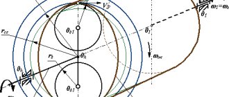
Operating principle: capacitive sensor. Everything is connected with the movement of the small plate (the head of the bar) along the large one (the scale of the bar), while the uncharged part of the large plate is charged and it seems like the charge flowing through the capacitor formed by these plates is proportional to the movement of the small plate. Something like this.
Search
Initial searches for information about the digital interface showed that many have seen it, some are even aware of it, but no one knows how to use it.
An in-depth search on non-Russian-language resources yielded more productive results. As it seemed at first, everything was quite simple and clear, chewed up by oscilloscopes, filmed on YouTube, etc., but there was no final and working option “right away.”
So, the main problem was finding information. The second problem was making a plug for this connector (which, in general, is not a connector at all, but just bare tracks on the board). They stubbornly refused to maintain contacts. In the end, I figured out to stick the tabs from the LPT port into a piece of eraser. The thing turned out to be unreliable, but quite suitable for the test. For the future, I decided to solder directly to the board without fail and bring out my own connector (pin CD-IN from the motherboard).
Solution
I came across an article on instructables.com and decided to repeat this feat.
To begin with, I’ll give you pictures brazenly stolen from there with the location of the contacts on the compass and the wiring diagram (I don’t see the point in redrawing it myself, and passing it off as your own is generally unforgivable):
Pins:
Scheme:
To match the voltages, I used a 200 Ohm resistor as recommended. There was no 10 µF capacitor, so I installed a 100 µF capacitor soldered from a dead motherboard.
Result
Having completed the soldering, I started writing the sketch.
By the way, in the absence of a development board, I came out of the situation by assembling the circuit on a “bed” from the IDE port, from the same motherboard. The sketch given in the above article worked without any questions, but did not bring satisfaction. The Chinese sketch from the comments refused to work “right away”, but made a much more serious impression, as a result of which it was subjected to serious “finishing”.
That's what came out of it
(or a ready-made sketch for Arduino UNO, IDE version 0022):
//CyberKot (aka... me! Shadow) //Arduino sketch that outputs data from a compass to the COM port //Version for Habr int dataIn = 11; //data bus, can be changed int clockIn = 2; //clock bus, don’t touch it, it’s necessary (read about attachInterrupt) int isin = 0; //d=1 mm=0 int isfs = 0; //minus int index; //bit counter unsigned long xData, oData; //new readings and old ones (later it will be clear why) int ledPin = 13; // flashing light for the 13th input (built-in, so that it is clear that nothing is hanging) int ledState = LOW; //flashing light status long previousMillis = 0; //when was the last time they blinked long interval = 500; // blinking interval long previousGetMillis = 0; long Timeout = 8; //timeout for reading bits in ms float stringOne; //temporary variables for output char charBuf[5]; char charBuf2[8]; void setup(){ digitalWrite(dataIn, 1); digitalWrite(clockIn, 1); pinMode(dataIn, INPUT); //bind the data bus to dataIn pinMode (clockIn, INPUT); //and clock to the 2nd input attachInterrupt(0,getBit,RISING); //and attach clock also to the 2nd input Serial.begin(9600); delay(500); index = 0; xData = 0; oData = 999; } void loop(){ if ((index !=0) && (millis() — previousGetMillis > Timeout) ) { //reset when timeout is exceeded index = 0; xData = 0; }; if (index >23) { //if the word is read completely if (oData !=xData) { /* This option is more elegant, in my opinion, but eats up an extra kilobyte if (isin==1){ //inches Serial.print ("inch: "); stringOne =xData*5/10000.00000; stringOne *=pow(-1,isfs); Serial.println(floatToString(charBuf2,stringOne,5,5)); }else { //mm Serial.print("mm: "); stringOne =xData/100.00; stringOne *=pow(-1,isfs); Serial.println(floatToString(charBuf,stringOne,2,5)); }; */ if (isin==1){ //inches if (isfs==1){ //minus Serial.print(“inch: -“); }else { Serial.print("inch: "); } stringOne =xData*5/10000.00000; Serial.println(floatToString(charBuf2,stringOne,5,5)); }else { //mm if (isfs==1){ //minus Serial.print(“mm: -“); }else { Serial.print("mm: "); } stringOne =xData/100.00; Serial.println(floatToString(charBuf,stringOne,2,5)); }; }; oData = xData; index=0; xData=0; }; if (millis() — previousMillis > interval) { //flashing light previousMillis = millis(); if (ledState == LOW) ledState = HIGH; else ledState = LOW; digitalWrite(ledPin, ledState); } } void getBit(){ //read bits and flags previousGetMillis=millis(); if(index < 20){ if(digitalRead(dataIn)==1){ xData|= 1<< precision; i++) { roundingFactor /= 10.0; mult *= 10; } temp[0]='\0′; outstr[0]='\0′; if(val < 0.0){ strcpy(outstr,"-\0″); val = -val; } val += roundingFactor; strcat(outstr, itoa(int(val),temp,10)); // integer part if( precision > 0) { strcat(outstr, “.\0″); // fractional unsigned long frac; unsigned long mult = 1; byte padding = precision -1; while(precision—) mult *=10; if(val >= 0) frac = (val - int(val)) * mult; else frac = (int(val)- val ) * mult; unsigned long frac1 = frac; while(frac1 /= 10) padding—; while(padding—) strcat(outstr,"0\0"); strcat(outstr,itoa(frac,temp,10)); } // spaces (for formatting) if ((widthp != 0)&&(widthp >= strlen(outstr))){ byte J=0; J = widthp — strlen(outstr); for (i=0; i< J; i++) { temp = ' '; } temp[i++] = '\0'; strcat(temp,outstr); strcpy(outstr,temp); } return outstr; }
Bottom line
Satisfied with the result, I decided to take the final photo, and a little “barefoot” advertising for effect:
Afterword
The description of the protocol contains a couple more interesting goodies, so there is an incentive for a reserve “for the future”
- fast mode (50Hz, versus 3Hz in default mode)
- "absolute" position processing
- "Zero" and "Mode" softkeys
[Links]
- barbell protocol
- work log of comrade j44
Advantages
- High accuracy. Electronic calipers can be classified as high-precision measuring instruments that operate with minimal error. The human factor is excluded. Namely, the risk of making mistakes in calculations.
- Simple controls. Operating a mechanical caliper requires some skill. Using a digital tool is much easier and more convenient.
- Speed of work. You save time on calculations. The electronic device displays ready-made data on the display. You only record and use the received data.
- Reset to zero at any point. Unlike a conventional caliper, the SCC can be zeroed at any measurement point.
- Connection to external electronic devices. Many models of digital calipers provide the ability to connect to a laptop or computer. Measurement results can be transmitted wirelessly, saved, and displayed on a monitor.
Design features of the device
The main elements of a digital measuring tool are similar to those found in standard models, but there are a number of electronic parts . In general, a digital caliper includes:
- sponges for measuring internal surfaces;
- sponges for measuring external surfaces;
- barbell;
- mobile frame;
- power source (battery or accumulator);
- roller that allows you to change the length;
- reset button;
- on/off button;
- inch/mm switch button.
The availability of additional options and buttons depends on a particular model.
Some instruments even have modules installed to transmit information via wireless technology. In general, the main elements are identical for all devices. In order to see the information obtained during measurements, you do not need to strain your eyes and peer - the contrast and high-quality screen displays large digital symbols, which is extremely convenient in low light conditions or problems with vision. The ruler of the electronic caliper has an additional scale in millimeters and inches, so it can be used even when turned off.