Pressure gauges are checked at least once a year at the Center for Standardization and Metrology (center for standardization and metrology), and at least once every six months - with a control pressure gauge (with accuracy class 1).
Pressure gauges must be installed from the level of the observation platform so that their readings are clearly visible to maintenance personnel, that is:
— at a height of up to two meters vertically, pressure gauge diameter 100 mm;
— at a height of two to three meters vertically, pressure gauge diameter 160 mm;
— at a height of three to five meters with a forward tilt of up to 30°, pressure gauge diameter 160 mm;
It is recommended to install shut-off valves at the pressure tapping point. When the medium pressure exceeds 0.3 MPa (3 kgf/cm2) and the length of the connecting line is more than three meters, installation of a valve is mandatory.
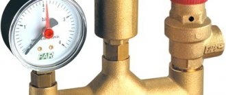
Pressure is measured with a pressure gauge, which is installed upstream of the shut-off valves or on the control panel. The working pressure gauge is mounted on a three-way valve, which ensures installation of a control valve and protection of the working pressure gauge from the direct action of the medium. Pressure gauges are used with a scale on which the arrow indicating the operating pressure during measurement is in the second third of the scale.
The following pressure gauges are not allowed for use:
- not having a seal or brand;
— with an overdue inspection period;
- with an arrow that does not return to the zero scale mark when turned off, or whose arrow, when set to “0,” deviates by an amount exceeding half the permissible error;
— in case of broken glass or other damage that may distort the accuracy of its readings.
The accuracy class of water pressure gauges must be at least 2.5. A red line is applied to the pressure gauge scale, corresponding to the highest permissible operating pressure.
To measure gas pressure, pressure gauges with an accuracy class of at least 1.5 are used. That is, the maximum permissible instrumental error when measuring gas pressure is 1.5% of the actual measured reading.
The pressure gauge scale has a division value. The division price is determined based on the scale segment between two marked values (numbers). The difference between them is taken and divided by the number of spaces between them.
Source: flaska.ru
Frequency of checking pressure gauges
Conducted:
1) every shift - The serviceability of the pressure gauge is checked using a three-way valve by setting the pressure gauge needle to zero, which is recorded in the shift log;
Checking the proper operation of the boiler pressure gauge - the so-called zero test - is performed in the following order:
a) the reading of the pressure gauge in the working position is noted and remembered;
b) by slowly turning the plug of the three-way valve to the left a quarter turn, the pressure gauge is disconnected from the boiler and connected (communicated) with the atmosphere; in this case, the pressure gauge needle should quickly but smoothly return to zero;
c) by turning the plug of the three-way valve to the right a quarter turn, the pressure gauge is again connected to the boiler; in this case, the arrow should quickly and smoothly return to its previous position; this will mean that the pressure gauge is working properly; the accuracy of its readings can only be confirmed by the readings of the control pressure gauge.
In cases where, when checking the serviceability of the pressure gauge, it is discovered that the pressure gauge needle does not go to zero when the pressure gauge communicates with the atmosphere or falls unevenly, jerkily, this means that the pressure gauge fitting and the three-way valve are clogged. It is necessary to immediately blow out the three-way valve; to do this, turn the three-way valve so that water (or gas, when checking gas pipelines) comes out. After purging, the three-way valve is set to its working position.
2) In addition to the specified check, the administration is obliged to do so at least once every 6 months. check working pressure gauges with a control working pressure gauge that has the same scale and accuracy class as the pressure gauge being tested, recording the results in the control check log.
3) At least once every 12 months. pressure gauges must be checked with a stamp or seal installed in the manner prescribed by Rosstandart of Russia. monthly - with the instrumentation and automation service - checking the operation of the boiler protection, the check is accompanied by a deviation of the parameters by simulation, and the results of the check are recorded in the operational log.
Didn't find what you were looking for? Use the search:
Best sayings:
For a student, the most important thing is not to pass the exam, but to remember about it in time.
9990 — | 7480 - or read all.
188.64.173.93 © studopedia.ru Not the author of the materials posted. But it provides free use. Is there a copyright violation? Write to us | Feedback.
Disable adBlock! and refresh the page (F5)
very necessary
All about verification
Now let's talk about how pressure gauges are checked, the timing and frequency of the devices being checked, and what rules should be followed.
If calibration of pressure gauges is carried out in laboratory conditions, then according to the rules it includes the following steps:
- visual diagnostics;
- setting the scale needle to the zero mark;
- diagnostics of the position of the arrow on this mark;
- The verification methodology includes identifying the main error.
Frequency and timing
As for frequency, at enterprises it is usually entered into the appropriate audit log. But since ordinary car enthusiasts usually do not keep a log of control checks of pressure gauges, this information can be recorded separately in a notebook. The frequency of diagnostics may vary depending on the device manufacturer; according to the rules, on average it can range from 12 to 60 months (the author of the video is the Avtozvuk.ua channel - Avtozvuk Database).
How often are pressure gauges checked?
Pressure gauges are measuring instruments that are used to monitor pressure in pipelines, pumping, boiler and other equipment. Their performance and accuracy of readings are of great importance for the normal operation of equipment and maintaining industrial safety. Therefore, equipment owners should have a clear understanding of how often pressure gauges are checked.
How often should pressure gauges be checked?
Checking a pressure gauge is a procedure for monitoring the metrological serviceability of the device and the accuracy of its readings. It is performed to allow the device to be used in areas that are subject to state regulation of ensuring the uniformity of measurements (GROEI). It is also necessary to check the readings of pressure meters to ensure their safe operation and monitor their serviceability.
Pressure gauges must be checked at a certain frequency, which is indicated by the manufacturer in the device passport.
It depends on the quality characteristics of the device and the requirements that it must meet in terms of the level of accuracy of its readings. The state sets a limit on the frequency of verification from 1 year to 5 years. The calibration interval begins in the month of manufacture of the device, regardless of how long it was stored in the warehouse and from what period its operation began. In order not to miss the deadline for the next control inspection of the pressure gauge, the enterprise must maintain a verification log.
Most often, manufacturers set an annual verification frequency.
However, many pressure gauges produced today also have a longer calibration interval, which makes their operation more convenient for their owners.
If the verification is successfully completed, the device is allowed for further operation during the next verification interval. If its readings do not meet the accuracy standards, then it becomes necessary to replace the pressure gauge.
What data should be on the stamp after sealing the pressure gauge?
What data should be on the stamp after sealing the pressure gauge?
(Rules for the design and safe operation of pressure vessels" PB 03 576-03)? — date of the next verification. + quarter and year of verification. — quarter and year of the next verification.
Interesting materials:
How to cancel a card subscription? How to unregister a SIM card? How to cancel all subscriptions from a Sberbank card? How to unsubscribe a card from Instagram? How to send money from an ATM to a card? How to unlink a bank card from iTunes? How to unlink a bank card from apple id? How to unlink a bank card from Facebook? How to unlink a bank card from an iPad? How to unlink a bank card from iTunes?
How verification is carried out
The readings of pressure meters must be checked by state metrological control authorities. Devices can also be verified by specialized organizations that have appropriate accreditation.
Verification is performed in the following order:
A control inspection of the device is carried out for the presence of external mechanical defects.
Standard conditions are created for verification: atmospheric pressure - about 760 mm Hg, air humidity - about 65%, air temperature - about 20 °C.
The dial arrow is set to 0.
Using special equipment, a reference pressure is created, which is measured by the calibrated and reference pressure gauges, after which their readings are compared.
To carry out verification, types of equipment such as a special metrological pressure gauge stand, a hydraulic press and a calibrator can be used. In this case, the use of a calibrator is allowed when checking pressure gauges for which state requirements for metrological control are not provided.
Source: grom.ru
OPERATIONS AND MEANS OF VERIFICATION
1.1. When performing verification, operations must be performed and verification tools specified in Table 1 must be used. .
Table 1
| Name of main operations | Method point number | Verification tools and normative and technical characteristics |
| Visual inspection | 4.2 | — |
| Testing piston systems | 4.3 | — |
| Determination of the roughness of the working surfaces of all piston pressure gauge systems (the roughness of low pressure piston systems and MOP-60S is determined only upon release from production) | 4.4 | Profilometer model 201 according to GOST 19300-73 |
| High pressure piston diameter measurement | 4.5 | Optimeter with a division value of no more than 1 micron according to GOST 5405-75; end gauges type MKP 3rd category according to GOST 9038-73 |
| Determining the perpendicularity of the load receiving plate to the axis of the MOP-60S piston | 4.6 | Installation for comparison with the working standard of the pressure unit US-16000-RE; block level group III according to GOST 9392-75 |
| Determination of the duration of free rotation of the MOP-60S piston | 4.7 | Installation US-16000-RE; stopwatch of groups 1-5 according to GOST 5072-72; thermometer with a lower measurement limit of no more than 15 °C, an upper measurement limit of not less than 25 °C, a division value of no more than 0.5 °C according to GOST 2045-71 or GOST 215-73 |
| Determination of the lowering speed of the MOP-60S piston due to liquid leaks through the gaps of the MOP-60S piston systems and low pressure | 4.8 | Installation US-16000-RE; ICH indicator according to GOST 577-68; thermometer - see paragraph 4.7 |
| Determination of the highest lowering speed of the MOP-60S piston under operating conditions | 4.9 | Installation US-16000-RE; ruler (150 and 300 mm) according to GOST 427-75; thermometer - see paragraph 4.7 |
| Determination of rotation drive quality | 4.10 | Installation US-16000-RE; gram and milligram weights, accuracy class 3 according to GOST 7328-73 |
| Determining the sensitivity threshold of a pressure gauge | 4.11 | See clause 4.10 |
| Determining the influence of detachable connections of the pressure gauge on the size of the reproduced pressure (not performed during periodic verification) | 4.12 | Same |
| Determination of required cargo mass values | 4.13 | » |
| Determination of the mass of the loads included in the set of the pressure gauge being verified | 4.14 | Exemplary laboratory scales of the 3rd category with the highest weighing limit of 5 kg according to GOST 16474-70; standard weights of the 3rd category according to GOST 12656-67 |
1.2. The measuring instruments indicated in table. , in addition to the working standard pressure unit and installation US-16000-RE, can be replaced by others that correspond in purpose, measurement limits and accuracy to the replaced means.
1.3. Measuring instruments used during verification must be verified by the state or departmental metrological service and have a verification certificate.
Regulations for checking pressure gauges: terms and conditions
Checking the readings of working instruments with their subsequent sealing, in accordance with the current GOST, is carried out at least once a year. In addition, the enterprise must carry out a scheduled inspection with a control pressure gauge at least once every six months. Each such check must be accompanied by a corresponding journal entry.
If the necessary control device is not available, you can check it with a sealed working pressure gauge. The main thing is that its scale and accuracy class coincide with the pressure gauge being tested.
Requirements for pressure gauges - Information and documents on labor protection and industrial safety
Requirements for pressure gauges
Each vessel and independent cavities with different pressures must be equipped with direct-acting pressure gauges. The pressure gauge is installed on the vessel fitting or pipeline between the vessel and the shut-off valve. Pressure gauges must have an accuracy class of at least: 2.5 - at a vessel operating pressure of up to 2.5 MPa (25 kgf/cm2), 1.5 - at a vessel operating pressure above 2.5 MPa (25 kgf/cm2). The pressure gauge must be selected with a scale such that the limit for measuring working pressure is in the second third of the scale. The owner of the vessel must mark the pressure gauge scale with a red line indicating the operating pressure in the vessel. Instead of the red line, it is allowed to attach a metal plate painted red to the pressure gauge body and tightly adjacent to the glass of the pressure gauge. The pressure gauge must be installed so that its readings are clearly visible to operating personnel. The nominal diameter of the body of pressure gauges installed at a height of up to 2 m from the level of the observation platform must be at least 100 mm, at a height of 2 to 3 m - at least 160 mm. Installation of pressure gauges at a height of more than 3 m from the site level is not permitted. A three-way valve or a device replacing it must be installed between the pressure gauge and the vessel, allowing periodic checking of the pressure gauge using a control valve. In necessary cases, the pressure gauge, depending on the operating conditions and the properties of the medium in the vessel, must be equipped with either a siphon tube, or an oil buffer, or other devices that protect it from direct exposure to the medium and temperature and ensure its reliable operation. On vessels operating under pressure above 2.5 MPa (25 kgf/cm2) or at ambient temperatures above 250°C, as well as with explosive atmospheres or hazardous substances of the 1st and 2nd hazard classes according to GOST 12.1.007-76 Instead of a three-way valve, it is possible to install a separate fitting with a shut-off valve for connecting a second pressure gauge. On stationary vessels, if it is possible to check the pressure gauge within the time limits established by the Rules by removing it from the vessel, the installation of a three-way valve or a device replacing it is not necessary. On mobile vessels, the need to install a three-way valve is determined by the vessel design developer. Pressure gauges and pipelines connecting them to the vessel must be protected from freezing. The pressure gauge is not allowed for use in cases where: there is no seal or stamp with a mark indicating verification; the verification period has expired; when it is turned off, the arrow does not return to the zero scale reading by an amount exceeding half the permissible error for this device; the glass is broken or there is damage that may affect the accuracy of its readings. Checking of pressure gauges with their sealing or branding must be carried out at least once every 12 months. In addition, at least once every 6 months, the owner of the vessel must carry out an additional check of the working pressure gauges with a control pressure gauge and record the results in the control check log. In the absence of a control pressure gauge, it is allowed to carry out an additional check with a proven working pressure gauge that has the same scale and accuracy class as the pressure gauge being tested. The procedure and timing for checking the serviceability of pressure gauges by maintenance personnel during the operation of vessels should be determined by the instructions for the operating mode and safe maintenance of vessels, approved by the management of the organization that owns the vessel.
____________________________________________________________ Rules for the design and safe operation of pressure vessels (approved by Resolution of the State Mining and Technical Inspectorate of the Russian Federation dated June 11, 2003 N 91)
naine.ru
How to check a gas pressure gauge
In general, the test consists only of comparing the data of the pressure gauge being tested with the readings of the control device or calculating the current gas pressure, then measuring it using a pressure gauge and comparing the data. To do this, you only need a control pressure gauge and a thermometer. If we describe this procedure in more detail, it looks like this:
- install the pressure gauge sensor into the container through a special fitting;
- when the pressure value is recorded, remove the pressure gauge and install a control device in its place;
- After comparing the readings of the two instruments, check the accuracy of the instrument readings;
- if the instrument readings do not coincide with the reference pressure gauge, it is necessary to adjust it so that under the same operating conditions the instruments show the same pressure values;
- there are adjusting bolts on the pressure gauge body, with the help of which adjustments need to be made;
- with an electronic analogue the actions are the same, only you need to take into account that this device has inertia, so the readings must be held for 8 to 10 s.
If there is no reference device, you must first calculate the working pressure using the formula P2=T2•P1/T1:
- this will require a vessel of a volume that is known or can be measured, containing air at normal atmospheric pressure and room temperature;
- the vessel is hermetically sealed and gradually heated;
- then the pressure inside the vessel is simply calculated using the formula, where T1 and T2 are the initial and final air temperatures in the vessel, and P1 is the atmospheric pressure.
- if the instrument readings do not coincide with the calculation, then it is necessary to adjust it to the data obtained during the calculation.
VERIFICATION
4.1. The pressure gauge to be verified must meet all the requirements of this method. If any requirement is not met, the pressure gauge being verified is rejected, an appropriate entry is made in the protocol for its verification, and the verification is completed.
4.2. When conducting an external inspection, the compliance of the calibrated pressure gauges with the following requirements must be established.
4.2.1. A pressure gauge submitted for periodic verification must have a certificate of previous verification. A pressure gauge undergoing initial verification (during release from production and after repair) must have a passport and a certificate of the results of operational tests.
4.2.2 The complete set of the pressure gauge must correspond to its assembly drawing. It is allowed to take the pressure gauge for periodic verification without weights.
4.2.3. The surfaces of the pressure gauge should not show signs of damage or corrosion. The presence of traces of chemical influence of the working fluid - glycerin with ethylene glycol on the outer surfaces of the high-pressure housing is allowed.
4.2.4. The lapped surfaces of piston systems must be smooth, without cavities, traces of corrosion, spiral and longitudinal marks. It is allowed to have several non-protruding ring marks on the surface of pistons that have been in operation.
4.2.5. The pressure gauge number must be marked on all pistons and cylinders and on the high-pressure housing.
4.2.6. Loads of equal nominal mass must be identical in shape and size; each load can have adjustable cavities closed with screw-in plugs.
4.2.7. Each load must indicate the pressure created by the load, serial and serial numbers.
4.3. Testing of piston systems consists of checking their compliance with the following requirements:
4.3.1. The connection of the MOP-60S piston with the load receiving plate must ensure that there is no possibility of their mutual movement.
4.3.2. The piston of any piston system, lubricated with working fluid and inserted into the corresponding cylinder, must rotate easily and move freely in the axial direction.
4.4. Determination of the roughness of the working surfaces of piston systems.
4.4.1. The quality of the working surfaces of the low-pressure piston and cylinder and the MOP-60S piston should be checked only during verification after release from production and repair; the high-pressure piston - during all verifications.
4.4.2. The roughness of all surfaces mentioned in paragraph 4.4.1 should be determined using a profilometer.
4.4.3. The height of profile irregularities at ten points of ground surfaces of a new low-pressure cylinder and new pistons should not exceed 0.15 microns; used - 0.3 microns.
4.4.4. The quality of the working surfaces of the MOP-60S cylinder and the high-pressure cylinder is checked visually for the absence of corrosion and cavities.
4.5. Measuring the diameter of the high pressure piston.
4.5.1. The diameter of the high-pressure piston should be measured in two mutually perpendicular sections every 10 mm along the working length at a distance of 5 - 75 mm from the lower edge of the piston.
4.5.2. The non-roundness of the ground surface of the piston should not exceed 0.2 µm, the non-cylindricality - 0.4 µm.
4.5.3. The results of measuring the piston diameter are compared with the value given in the previous certificate. If the change in the average diameter value for one year or less exceeds 0.6 µm for a pressure gauge with an accuracy class of 0.1 and 1.2 µm for a pressure gauge with an accuracy class of 0.2, a letter is issued for this pressure gauge to the state supervisory authority at the place of use of the device about the need for inspection conditions of its operation for compliance with operational documentation. After repair, this device can be certified as an exemplary one only if there is a certificate from the state supervision authority about satisfactory operating conditions.
4.6. Determination of the perpendicularity of the load receiving plate to the axis of the MOP-60S piston.
4.6.1. The pressure gauge to be verified is assembled on the US-16000-RE installation in accordance with the instructions in the technical description of the installation. Open the pressure gauge valve, fill the low pressure cavity of the pressure gauge with transformer oil according to clause 3.2.5. remove air from it. Using a press, raise the MOP-60S piston 2 - 4 cm from the lower position, close the oil pumping valve. By pressing the piston plate with your hand, make sure that there is no air in the cavity - the piston should not spring. Using a press, lower the MOP-60S piston to its lowest position (all the way); in this case, the required amount of oil will be in the low-pressure cavity.
4.6.2. Install the MOP-60S piston in a vertical position. To do this, place a level on the piston plate in the center. The set screws adjust the position of the piston so that with any rotation of the plate the change in level readings does not exceed 1°.
4.6.3. Check the perpendicularity of the plate to the piston axis by setting a level on a stationary plate (in the center) in six different directions, at approximately 30° intervals. In this case, the deviation of the level readings from the sump should not exceed 5 inches.
4.7. Determination of the duration of free rotation of the MOP-60S piston.
4.7.1. The first weight from the US-16000-RE installation kit is placed on the MOP-60S piston plate, and the piston is raised to the working position (see paragraph 2.1.2).
4.7.2. The duration of rotation of the piston is determined as the time of its free rotation from the moment the spinning drive of the US-16000-RE installation loader (100 rpm) ends until it stops completely. Measure the ambient air temperature with an error of no more than 0.5 °C.
4.7.3. The duration of rotation, depending on the ambient temperature, must be no less than indicated in the table. .
table 2
| Temperature, °C | Minimum permissible duration, s, of free rotation of MOP-60S pistons for an accuracy class pressure gauge | |
| 0,1 | 0,2 | |
| 15 | 75 | 50 |
| 16 | 75 | 50 |
| 17 | 80 | 55 |
| 18 | 85 | 55 |
| 19 | 90 | 60 |
| 20 | 90 | 60 |
| 21 | 95 | 60 |
| 22 | 100 | 65 |
| 23 | 105 | 65 |
| 24 | 110 | 70 |
| 25 | 115 | 70 |
4.8. Determination of the lowering speed of the MOP-60S piston due to liquid leaks through the gaps of the MOP-60S piston systems and low pressure.
4.8.1. Seven weights are placed on the plate of the MOP-60S piston in numerical order, it is lifted using a hand press into the working position (section 2.1.2) and set into rotation. In this case, the press for pumping oil into the low-pressure cavity of the pressure gauge must be turned off by the valve of the US-16000-RE installation, and the pressure gauge valve must be open.
4.8.2. Using an indicator and a stopwatch, measure twice the time during which the piston drops to a length of at least 0.3 mm and calculate the speed.
4.8.3. The speed of lowering the piston, depending on the ambient temperature, should not exceed the value indicated in the table. .
Table 3
| Temperature, °C | The highest permissible lowering speed of the MOP-60S piston due to liquid leakage through the gaps of the MOP-60S piston systems and low pressure, mm/min, for an accuracy class pressure gauge | |||
| 0,1 | 0,2 | |||
| upon release from production | periodic and upon release from repair | upon release from production | periodic and upon release from repair | |
| 15 | 0,16 | 0,24 | 0,32 | 0,48 |
| 16 | 0,17 | 0,26 | 0,34 | 0,52 |
| 17 | 0,18 | 0,27 | 0,36 | 0,54 |
| 18 | 0,19 | 0,28 | 0,38 | 0,56 |
| 19 | 0,20 | 0,29 | 0,40 | 0,58 |
| 20 | 0,20 | 0,30 | 0,40 | 0,60 |
| 21 | 0,21 | 0,31 | 0,42 | 0,62 |
| 22 | 0,22 | 0,32 | 0,44 | 0,64 |
| 23 | 0,22 | 0,34 | 0,46 | 0,68 |
| 24 | 0,23 | 0,36 | 0,47 | 0,72 |
| 25 | 0,24 | 0,38 | 0,48 | 0,76 |
4.9. Determination of the highest lowering speed of the MOP-60S piston under operating conditions.
4.9.1. Close the high pressure valve of the installation. In the pressure gauge being verified, a pressure of about 0.2 GPa is created in accordance with the instructions in the technical description of the installation and maintained for 5 - 6 minutes until the lowering speed of the MOP-60S piston stabilizes.
4.9.2. Using a ruler and a stopwatch, determine the time it takes for the piston to lower to a length of 30 mm three times and calculate the speed. Before measurement, the piston is raised to the upper position, the stopwatch is turned on when the distance from the cup to the weight receiving plate is about 60 mm.
4.9.3. The lowering speed of the MOP-60S piston, depending on the temperature, should not exceed the value indicated in the table. .
Table 4
| Temperature, °C | The highest permissible lowering speed of the MOP-60S piston under operating conditions, mm s, for an accuracy class pressure gauge | |||
| 0,1 | 0,2 | |||
| with upper limit of measurement, 1 Pa | ||||
| 1 | 1,5 (1,6) | 1 | 1.5 (1,6) | |
| 15 | 0,6 | 0,9 | 0,9 | 1,2 |
| 16 | 0,6 | 0,9 | 0,9 | 1,3 |
| 17 | 0,7 | 1,0 | 1,0 | 1,4 |
| 18 | 0,7 | 1,1 | 1,1 | 1,5 |
| 19 | 0,8 | 1,2 | 1,2 | 1,7 |
| 20 | 0,8 | 1,2 | 1,2 | 1,8 |
| 21 | 0,9 | 1,3 | 1,3 | 1,9 |
| 22 | 0,9 | 1,4 | 1,4 | 2,1 |
| 23 | 1,0 | 1,5 | 1,5 | 2,2 |
| 24 | 1,0 | 1,6 | 1,6 | 2,3 |
| 25 | 1,0 | 1,7 | 1,7 | 2,5 |
4.10. Determination of the quality of the drive for rotation of low and high pressure pistons.
4.10.1. In the pressure gauge being verified, a pressure of 0.2 - 0.4 GPa is created, the piston is raised by 3 - 5 cm. Using a toggle switch, the direction of rotation of the low and high pressure pistons is changed several times. Switching is performed after 5 - 10 s, recording the readings of the resistance differential pressure gauge. Then raise the piston by 10 cm, observe the nature of the change in the differential pressure gauge readings during the process of lowering the piston. At two positions of the piston - at a height of 7.5 cm and at the bottom - the differential pressure gauge readings are taken. Repeat the measurements in the opposite direction of rotation.
4.10.2. The maximum change in pressure caused by switching the direction of rotation should not exceed 0.04 MPa for instruments of accuracy class 0.2 and 0.02 MPa for instruments of accuracy class 0.1.
The dependence of the reproducible pressure on the height of the MOP-60S piston should be monotonic, close to linear. The change in the readings of the resistance differential pressure gauge when the piston is lowered by 7.5 cm should correspond to a decrease in the mass of the loads by 5.6 g with a permissible deviation of 1.5 g for instruments of accuracy class 0.2 and 1 g for instruments of accuracy class 0.1.
4.11. Determination of the pressure gauge sensitivity threshold.
4.11.1. In the pressure gauge being verified, a pressure corresponding to the upper limit of measurement is created, and the MOP-60S piston is raised to the working position (clause 2.1.2). After the readings of the resistance differential pressure gauge have stabilized, the sensitivity threshold of the pressure gauge is determined by placing a MOP-60S piston on the plate or removing an additional weight and observing the readings of the resistance differential pressure gauge.
4.11.2. The application or removal of a 5 g weight should cause a change in pressure different from the calculated value
no more than 20% ( d
n.d and
d
in.d are the diameters of the low and high pressure pistons, respectively).
4.12. Determination of the influence of detachable connections of the pressure gauge on the reproducible pressure.
4.12.1. The inconsistency of the reproducible pressure, due to the presence of detachable connections, is checked by threefold comparison with the working standard after reinstalling the high-pressure piston system of the pressure gauge being verified.
4.12.2. To perform comparisons in the installation, in accordance with the instructions in the technical description, create with the valve open a pressure equal to the upper limit pressure of the pressure gauge being verified. The pressure is set according to the working standard. Preliminary hydrostatic balancing of the pistons of the working standard and the pressure gauge being verified is performed by selecting weights on the piston plate of the pressure gauge being verified so that both MOP-60S pistons are in a suspended state. The zero of the differential pressure gauge is fixed and the valve is closed.
Observing the readings of the differential pressure gauge in the operating position of the MOP-60S piston, the pressure in the disconnected parts of the installation is equalized by selecting weights on the piston plate of the pressure gauge being verified. Then the valve is opened and the differential pressure gauge readings are checked for zero.
If necessary, the pressure equalization operation is repeated until the differential pressure gauge readings coincide with the valve closed and open with a deviation within 0.05 MPa for pressure gauges with an accuracy class of 0.1 and 0.1 MPa for pressure gauges with an accuracy class of 0.2.
At the end of the comparison, fix the mass of weights on the piston plate of the pressure gauge being verified, perform comparisons at a pressure of 0.3 GPa, press the high-pressure cylinder out of the body of this pressure gauge and press it back in, turning it around its axis at an angle of about 90°, pump a little liquid, and finish assembling the pressure gauge , repeat comparisons.
4.12.3. The change in pressure reproduced by the pressure gauge being verified should not exceed 0.2 MPa for pressure gauges of accuracy class 0.1 and 0.5 MPa for pressure gauges of accuracy class 0.2.
4.13. Determination of the required mass values of cargo.
4.13.1. The weight of the loads is determined by comparing the pressure gauge being verified with the working standard of the pressure unit over the entire operating range at pressures that are multiples of 0.1 GPa (1000 kgf/cm2). The difference in pressure reproduced by the pressure gauge being verified and the working standard of the pressure unit, recorded by the differential pressure gauge, i.e. the permissible error of comparison should not exceed the values given in table. .
Table 5
| Pressure, GPa | Permissible comparison error, MPa, for a pressure gauge of accuracy class | Pressure, GPa | Permissible comparison error, MPa, for a pressure gauge of accuracy class | ||
| 0,1 | 0,2 | 0,1 | 0,2 | ||
| 0,1 | 0,02 | 0,05 | 0,9 | 0,20 | 0,40 |
| 0,2 | 0,05 | 0,10 | 1,0 | 0,20 | 0,40 |
| 0,3 | 0,05 | 0,10 | 1,1 | 0,20 | 0,40 |
| 0,4 | 0,10 | 0,15 | 1,2 | 0,25 | 0,50 |
| 0,5 | 0,10 | 0,20 | 1.3 | 0,25 | 0,50 |
| 0,6 | 0,10 | 0,25 | 1,4 | 0,30 | 0,60 |
| 0,7 | 0,10 | 0,30 | 1,5 | 0,30 | 0,60 |
| 0.8 | 0,15 | 0,30 | 1.6 | 0,30 | 0,60 |
4.13.2. Mass i
the th load
Mi
, except the 1st, is calculated using the formula
| Mi = |
where M
Σ
i
is the total mass of balancing weights on the piston plate of the pressure gauge being verified at a pressure of 0.1 -
i
GPa;
The mass of the 1st load is determined by the formula
| Mi = |
where Hp
,
H
p is the distance between the planes of the upper end of the low-pressure piston and the lower end of the MOP-60S piston under operating conditions and during verification, respectively.
4.14. Determination of the mass of the loads included in the set of the pressure gauge being verified.
4.14.1. The mass of goods is determined by weighing on scales with the largest weighing limit of 5 kg. Deviations of the mass of the loads from the values obtained in clause 4.13 should not exceed 0.5 g for pressure gauges of accuracy class 0.1 and 1 g for pressure gauges of accuracy class 0.2.
Checking pressure gauges: terms, methods, rules
Various measuring instruments can be installed in a compressed air injection system; a pressure gauge has become widespread. Like many other devices, this one must undergo periodic maintenance. Only in this case can you be sure that it will last for a long period, and the readings obtained will be accurate. Let's consider all the features of the pressure gauge checking procedure in more detail.
Functionality check:
GOST verification rules (frequency or calibration) - 12 months.
Whereas the starting point should be taken - a month from production. Now there are also pressure gauges that can be verified once every 2 years.
That is, the pressure gauge must be checked at least once a year and at the time of release. It is worth noting that the shelf life of the device (in which it is not involved) is not taken into account.
All verifications carried out with a control pressure gauge (in the absence of which a pressure gauge identical to the verification one can be used) are recorded in the inspection log.
The timing of verification procedures is carried out in accordance with the instructions approved by the owners of the vessels.
Frequency of checking pressure gauges
A pressure gauge is a device that measures pressure in a device or container in a certain section of the pipeline. Periodic checking helps avoid major problems. It is worth considering that verification of pressure gauges should be carried out exclusively taking into account the type of device:
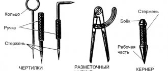
In order for the calibration of pressure gauges to be carried out with high efficiency, attention should be paid to their design features. Spirals are characterized by the following features:
- Inside the housing there is a spiral, which is connected to the transmitting elements. It is made using a special metal with high elasticity.
- The dial is connected to a spiral, due to which the position of the arrow changes. The dial operates on a mechanical principle and is represented by a scale with an arrow. Typically, units of measurement and other more important information are displayed on the surface.
- As the pressure increases, the spiral unwinds, causing the needle to deflect to a greater extent. The size of this element determines the range over which measurements can be taken.
Membrane versions operate due to a flat plate that is connected to the transmitting element. As the pressure increases, the membrane bends to a greater extent, causing the needle to move.
The frequency of verification depends on a variety of factors, including the area of application of the device. In some cases it is necessary to carry out the procedure once a year, in others for 5 years. Incoming inspection is carried out by many organizations with an on-site visit, since in some cases the procedure must be carried out by a certified specialist and taking into account the requirements for processing.
Calibration of the pressure gauge and other procedures used to be carried out once a year, but due to the use of modern technologies in production, the period has been doubled.
Due to this, the accuracy of the pressure gauge readings is at a high level.
Today, state verification is carried out when monitoring the condition of measuring instruments of critical systems. The received data is decrypted in a variety of ways, so the procedure is carried out exclusively by a specialist.
PREPARATION AND CONDITIONS OF VERIFICATION
3.1. The ambient temperature should be 20 or 23 °C with a permissible deviation:
±2 °С - for instruments of accuracy classes 0.6 and 1;
±5 °С - for instruments of accuracy classes 1.5; 2.5 and 4.
When using a standard indicating deformation device for verification, the permissible temperature deviation must correspond to its normal conditions, otherwise a correction for the influence of temperature must be introduced into the readings of the standard device.
3.2. Vibration (shaking) should not cause the oscillation range of the needle or pen to exceed 0.1 of the permissible basic error limit of the device, unless otherwise specified in the technical specifications for the device.
3.3. The device must be connected to a device for creating pressure and be in a position corresponding to the designation on the device or as indicated in the documentation. If there is no operating position designation, then during verification the device must be installed so that the plane of the dial is vertical with a permissible deviation of ±5 ° (unless otherwise specified in the technical documentation), and the numbers and signs must be located without tilt.
3.4. For devices with an upper measurement limit of up to 250 kPa inclusive, as well as those marked “G”, the pressure in the device must be created by air or neutral gas, except in cases specifically specified in the documentation for the device.
For instruments that have on the dial a designation of the state of the medium on which the instrument is calibrated, the working fluids must be:
a) air or neutral gas - for devices with the designation “G” (if the working medium of the reference device is liquid, it is necessary to use a gas-liquid separation chamber);
b) liquid - for devices marked “for liquid” or “L” (if the working medium of the reference device is air or neutral gas, it is necessary to use a gas-liquid separation chamber).
3.5. The operating environments of reference instruments must comply with their documentation.
It is allowed to use other environments that do not cause corrosion of parts and components of the reference device, if they are specified in the technical documentation for the device being verified.
3.6. In case of a special version of the device for measuring the pressure of the working medium, the name of which is printed on the dial or given in the accompanying documentation, when verification on the media specified in clause 3.5 is unacceptable, the device must be verified using a separation chamber on the working medium or on a medium that does not react with the working medium. environment.
In this case, the error introduced by the separation chamber should not exceed 0.2 of the limit of the permissible basic error of the device.
3.7. Instruments intended for measuring oxygen pressure must be accompanied by a written guarantee of degreasing, without which their verification is prohibited. Water or air is recommended as a working medium that transmits pressure to devices for measuring oxygen pressure. Environments contaminated with oil and organic impurities are not allowed.
It is allowed to verify such devices without using a separation chamber. To do this, the internal cavities of the pressure creation device and the reference device must be degreased and filled with clean water. Degreasing must be confirmed by the appropriate document. A deformation pressure gauge labeled “oxygen” should be used as a reference device.
It is allowed to use other liquids (gases) instead of water (air), the interaction of which with oxygen is safe.
3.8. The device for creating pressure must ensure a smooth increase and decrease in pressure, as well as constant pressure during readings and keeping the instruments under pressure equal to the upper measurement limit.
3.9. If the working medium during verification is liquid, then the end of the fitting of the device and the end of the fitting of the standard deformation pressure gauge (or the end of the piston of a deadweight pressure gauge) must be in the same horizontal plane with the permissible error:
(1)
where g is the limit of permissible basic error of the device as a percentage of the standard value (upper measurement limit P
max);
r is the density of the working medium;
g is the acceleration of free fall.
3.10. If it is not technically possible to fulfill the requirements of clause 3.9 of this methodology, a correction D p
, taking into account the influence of the working environment column:
D p
= rgDH
(
2)
The correction is added to the readings of the device whose end level is higher.
Note. For instruments with a zero corrector, it is possible to take into account the correction by setting the pointer to the zero mark after connecting to the reference instrument.
3.11. Devices presented for verification complete with separating devices are verified taking into account the additional error of the separator and the installation rules provided for in the regulatory and technical documentation for these sets.
3.12. The device must first be kept in a non-operating state at the ambient temperature specified in clause 3.1., not less than:
12 hours - if the difference in air temperature in the room for verification and the place from where the device is brought in is more than 10 ° C;
1 hour - if the difference in air temperature in the room for verification and the place where the device is brought in is from 1 to 10 °C.
If the difference between the indicated temperatures is less than 1 °C, exposure is not required.
3.13. Devices with a sign on the scale ("Attention") must be accepted for verification only with accompanying documentation.
Methodology for checking pressure gauges
There are quite a large number of different technologies that allow you to determine the condition of a measuring device. Checking of technical pressure gauges should be carried out exclusively by professionals, since mistakes made can cause a decrease in the accuracy of the readings. Services should only be provided by specialists who have received appropriate permission.
There are several most common verification technologies:
- When using a hydraulic press. In this case, the measuring device is installed between two elements of the device. It is worth considering that this measurement technology is characterized by low error. There are quite a large number of different types of hydraulic presses, all of them are characterized by their own specific features. This design is found exclusively in specialized stores; to use it you must have certain skills and knowledge.
- When using a metrological stand. In this case, the main indicators are taken with a minimum error at the established control points. Such a device creates the required pressure in the system. Among the features of using a metrological stand, we note that the measurement errors are quite high. However, the design features make it possible to significantly expand the scope of application of the device, for example, in the case of high pressure in the system.
- When using a special calibrator. This device can be purchased today in a specialized store for independent verification of the device. When choosing a calibrator, attention is paid to the range of indicators it can be used in. Most of the models work according to the same scheme.
The latter method allows you to check devices that do not require sealing after the procedure.
The device is characterized by high mobility and can be used without special training.
REGISTRATION OF VERIFICATION RESULTS
5.1. The verification results are recorded in the protocol.
5.2. For pressure gauges that meet the requirements of this methodology, a certificate of the established form is issued.
The reverse side of the certificate is filled out according to the form specified in the application.
5.3. If the pressure gauge is submitted for verification without weights, then a corresponding note is made in the certificate. In this case, the results of adjustment and inspection of cargo must be documented with an additional certificate from the local metrological service authority.
5.4. Pressure gauges that do not meet the requirements of this methodology are not allowed for use; the previous certificate is stamped “Rejected” indicating the reason and date of rejection signed by the state verifier.
Checking pressure gauges: rules
Pressure gauges must be checked exclusively taking into account the basic rules and recommendations, since mistakes made can lead to a decrease in the accuracy of the product. The basic rules are as follows:
- First, the pressure gauge is inspected to determine the condition of the mechanism. Damage to the device may indicate that verification is not worthwhile. Some of the defects can be eliminated, for example, by replacing the protective glass, it all depends on the features of the specific pressure gauge model.
- The conditions closest to operational ones are created. An example is the indicator of air humidity, atmospheric pressure and temperature in the room.
- At the beginning of the test, the needle must be at zero. Due to this, the possibility of an error at the time of measurement is eliminated.
VERIFICATION OPERATIONS
1.1. The operations performed when checking instruments must correspond to those indicated in table. 1.
Table 1
| Verification operations | Number of paragraphs of this recommendation |
| Visual inspection | 5.1 |
| Setting the arrow (pen) to the zero mark of the scale (zero reference line of the diagram) | 5.2 |
| Checking the position of the arrow (pen) at the zero mark of the scale (zero reference line of the diagram) | 5.2 |
| Determination of basic error and variation | 5.3 |
| Verification operations for multi-pointer instruments | 5.4 |
| Operations for checking instruments with a control arrow | 5.5 |
| Operations for checking instruments with a signaling device | 5.6 |
| Verification operations for recording instruments | 5.7 |
Requirements for calibration of pressure gauges
To verify the basic parameters of the measuring device, attention should be paid to the basic requirements that apply to the procedure in question. These include the following points:
- Before the actual inspection, you should provide documents that confirm that you have completed this procedure previously. The results that were obtained earlier may also be required during the next verification. Some companies do not carry out the procedure in question if the appropriate document is not available.
- If the device is part of a critical mechanism, then it must have a seal. Otherwise, the mechanism cannot be used for its intended purpose.
- Depending on the pressure in the system, the most suitable equipment is selected. The most important parameters are the measurement range and the scope of application of the device.
- The data from the device used must be easily readable. For this purpose, the most optimal working conditions are selected.
- The installation of a pressure gauge must be carried out exclusively in compliance with all safety measures. A fairly common mistake is reducing the strength of the connection. If high pressure is applied, a leak may occur, which will reduce the pressure in the system.
All established standards are taken into account by the specialist who verifies the device. If the requirement is not taken into account, the condition of the structure cannot be verified with high accuracy.
Time limits for checking pressure gauges
Most attention is paid to deadlines. The purpose of calibration is to increase the accuracy of the readings taken. Among the features we note the following points:
- When submitting a pressure gauge for verification, you need to be prepared for the fact that it will be in the company for 14 working days. Some companies complete the task much faster. Do not forget that verification requires quite a lot of time, which eliminates the possibility of making an error.
- For reference devices, the period is reduced to 7 working days. When contacting a company that provides the services in question, you can find out how long the work will be completed.
- You can reduce the timeframe by submitting documents in advance. Many companies allow you to call and order verification, as well as send documents electronically for their preliminary verification.
- The measuring device can only be removed from the device by calling a specialist who provides the appropriate services. Do not forget that making mistakes at the time of installation can compromise the integrity of the highway.
- The tests carried out must last for a certain period. Manufacturers often add instructions for using calibration devices to the package.
You can carry out the procedure in question yourself only if the device is installed as an element of non-critical mechanisms.
Calibration Features
Next, we invite you to learn about calibrating the device.
The device calibration procedure itself can generally be divided into several main steps:
- Diagnostics of parameters, which we will discuss below, using a known standard or input data.
- The next step will be to adjust the device until the obtained indicators become equal or proportional in accordance with the existing input data.
As for calibration itself, this procedure includes many checks and adjustments. When the device is fully calibrated, this will mean that it will be able to obtain the most accurate values of the parameters that you measure.
Now let's briefly talk about the equipment that may be needed for calibration. The basic equipment that will be required should include a so-called reference device, a source of operating pressure that can be adjusted as needed. You will also need elements to connect the device to a pressure source and a reference device and several tools that will be useful for adjusting the device. The purpose of measuring devices is to transfer the sizes of physical units from standards to working devices.
As for working measuring instruments (measuring devices), their purpose is to carry out measurements in industry. According to their accuracy class, they can be divided into technical and laboratory. Since not every car enthusiast has such devices, taking measurements can be problematic.