All about ball screws
A ball screw
is a type of linear drive that transforms rotary motion into linear motion, which has the distinctive feature of extremely low friction.
A shaft (usually steel - made from high-carbon types of steel) with a specific shape of running tracks on the surface acts as a high-precision drive screw interacting with the nut, but not directly, through sliding friction, as in conventional screw-nut transmissions, but through balls, through rolling friction . This determines the high overload characteristics of the ball screw and very high efficiency. The screw and nut are manufactured as a matched pair to very tight tolerances and can be used in applications where very high precision is required. The ball nut is usually slightly larger than the slide nut due to the ball recirculation channels located in it. However, this is practically the only point in which the ball screw is inferior to sliding friction screw drives.
Scope of application of ball screws
Ball screws are often used in aircraft and rocketry to move steering surfaces, and also in cars to drive the steering rack from an electric steering motor. The widest range of ball screw applications exists in precision engineering, such as CNC machines, robots, assembly lines, component installers, as well as mechanical presses, injection molding machines, etc.
Ball screw history
Historically, the first precision ball screw was made from a fairly low precision conventional screw, onto which a structure of several nuts was installed, tensioned by a spring, and then lapped along the entire length of the screw. By redistributing the nuts and changing the direction of the tension, the pitch errors of the screw and nut could be averaged out. Then, the resulting step of the pair, determined with high repeatability, was measured and recorded as a passport. A similar process is currently periodically used to produce ball screws.
Ball screw application
In order for the ball pair to serve its entire design life while preserving all, incl. accuracy parameters, it is necessary to pay great attention to the cleanliness and protection of the working space, to avoid contact of dust, shavings and other abrasive particles with the steam. This is usually solved by installing steam, polymer, rubber or leather corrugated protection, which prevents foreign particles from entering the work area. Another method is to use a compressor, supplying filtered air under pressure to an open-mounted propeller. Ball screws, thanks to the use of rolling friction, can have a certain preload, which removes the backlash of the transmission - a certain “gap” between the rotational and translational motion that occurs when changing the direction of rotation. Eliminating backlash is especially important in computer-controlled systems, which is why preloaded ball screws are especially often used in CNC machines.
Disadvantages of Ball Screws
Depending on the elevation angle of the raceways, ball screws may be subject to reverse transmission - low friction causes the nut to not lock, but to transmit linear force into torque. Ball screws are generally undesirable for manual feeds. The high cost of ball screws is also a factor that often inclines the choice of machine builders in favor of more budget-friendly gears.
Advantages of Ball Screws
The low coefficient of friction of the ball screw causes low dissipation and high transmission efficiency - much higher than that of any other analogues. The efficiency of the most common ball screws can exceed 90%, compared to a maximum of 50% for metric and trapezoidal lead screws. Virtually no slip significantly increases the service life of the ball screw, which reduces equipment downtime during repairs, replacement and lubrication of parts. All this, combined with some other advantages, such as higher achievable speed, reduced power requirements for the electric drive of the propeller, can be a significant argument in favor of a ball screw, as opposed to its high cost.
Ball screw SFU1605 from China: assembling a large CNC router
Review of a specific product: a set of ball screws type SFU1605-1000 as elements of CNC machine gears. The review will contain brief information about what a ball screw is and how to use it. As a matter of fact, when trying to calculate and build an amateur CNC machine (milling machine) on my own, I was faced with the fact that we either have expensive components for machines, or not quite what need to. Specifically, there was a problem with purchasing a lead screw or ball screw as transmission elements along the axes of the machine.
There are the following types of gears for CNC:
- Belts
are used together with gears mainly for lasers, since the laser has a light “head” - serrated
_ These are spur or helical racks and gears for moving along them - Lead screws
are T8 type (mainly used in 3D printers and other small-sized machines), TRR type, for example TRR12-3 with a POM nut (plastic). - Ball screws
are a screw and a nut for it. The nut has special bearings that move along a channel inside the nut.
As a rule, they are chosen taking into account the load (weight of the moving portal/axle) and the influence of backlash. In ball screws, there is less play due to bearings; they are considered more accurate and preferable, but at the same time they are quite expensive for homemade products.
Quote from Wiki:
A helical gear is a mechanical transmission that converts rotary motion into linear motion, or vice versa. In general, it consists of a screw and a nut....
one of the main types: ball screw (ballscrew).
Ball screw
(hereinafter referred to as a ball screw) is a more reliable analogue of a lead screw, but instead of a brass nut (or a plastic one as for TRR-12-3 type screws, as I had on my old project), there is a special nut with balls that engage with the ball screw, select all the play and at the same time reduce friction. To independently assemble a CNC machine or 3D printer on a ball screw, you will need a ball screw, a nut for it, a coupling for attaching it to the motor and hanging bearings.
Here is a small render from the Internet. You can clearly see how the balls are distributed along the screw. Similar to T8, the ball screw has multi-start threads.
For the CNC machine, two sets of 1000 mm ball screws were needed for the Y axis, and 600 mm for the X axis. I received the ball screw by courier mail. This is not an expensive option, considering the weight of the package (about 8 kg).
The packaging is a long narrow box, inside the cardboard package there is a synthetic bag type packaging, a very durable material. Carefully unpack. Inside is the familiar bubble-wrap, that is, a bubble film that protects the product from mechanical influences.
We remove the film. The parcel contained three sets of ball screws: a screw + a nut, of different sizes. Two sets are designed to move the machine portal along the Y axis, the third short set is for the X axis.
All kits are wrapped in inhibitory green film, which prevents moisture from entering. Plus there is a fair amount of lubricant on the surface of the product.
In this kit, I paid extra for ending one kit at 600 mm (it turned out cheaper this way). I ordered the ending (machined) separately from the same seller (he has such a service in the catalogue), it cost 1 buck for each end of the screw. A good option for those who take screws in a specific size.
That's what the "ending" is. This is grinding a 16.05mm screw to 12mm diameter to fit into the outboard bearing, then the threaded part to secure the screw, then grinding down to 10mm to clamp the end into the elastic coupling of the engine
The parcel arrived safe and sound, courier delivery is not Russian Post. I applied a ruler in different places to find the curvature. I couldn’t find it, the ball screws are straight. Installation and use will show the rest.
Photo of the threaded part of the screws
Appearance of the kits
And further. The nuts arrived already screwed onto the screw... The balls are filled inside, there is lubricant. When ordering, ask for spare balls, at least a few.
Next, we begin to check the sizes of the screws. Short by 600 mm. That is, these 600 include a threaded part on both sides. The actual travel along the machine axes will be less. note
, that in the lot the size is indicated for a ball screw along with threads and turned ends, that is, the working stroke of the ball screw will be less than its length! Specifically, 65 mm less.
Second and third ball screws 1000 mm
The diameters of the threaded part are respectively 1605
seats for bearings BK12 and BF12 10 and 12 mm, respectively.
And on the other side under the bearing. The diameter of the SFU1605 nut itself is 28 mm.
If you remove the plastic plug from the nut, you can service the ball screw, lubricate or change the balls. I check that everything is in stock))))
In fact, you can remove the nut, wipe it, re-lubricate it, and put the balls back in. The plastic cover is secured with a countersunk screw for a 2.5 hexagon (you can see it at the top).
To install the ball screw in the machine, you will need suspension bearings of type BK12+BF12 (straight) or FK12+FF12 (flange), an elastic coupling 6.35*10mm for connection to a NEMA23 type motor on one side (6.35mm) and to the end of the ball screw on the other (10mm ).
External view of the assembled axle kit: bearings BK12, BF12, retaining ring, nut for fixing the screw, nut holder SFU1605, coupling for the motor and the screw itself with the nut.
Ball screw dimensions for those who are planning to purchase or are designing machine mechanics
And separately for SFU1605
Appearance of nut SFU1605
Appearance of bearings BK12+BF12 (left) and bearings with flange FK12+FF12 (right). They differ in the way they are installed on the frame.
The ball screw nut is attached through a special adapter housing. Nut holder SFU1605, aluminum
For installation on one axis (I have two per axis for Y) you will need:
- 1 x screw SFU1605-1000mm;
- 1 x bearing BK12;
- 1 x BF12 bearing;
- 1 x motor coupling 6.35x10mm
- 1 x retaining ring
- 1 x nut.
When assembled it looks like this:
We attach it to the profile/frame of the machine through the holes in the bearing.
For FK12/FF12 bearings everything is similar, only they must be attached with a flange to the hole for the ball screw. The meaning doesn't change. Now a little video explaining the principle of operation of a ball screw. Pay attention to the movement of the balls (through the built-in channel inside the nut).
And this is how the threads are rolled onto the ball screws. Processing the ends of the ball screw (what I called “machined”). For such an operation they ask us for 600...1000 rubles, in China $1.
The following photographs give a general idea of the use of ball screws in CNC machine design.
Here is a photo of a homemade machine in which the ball screw is fixed motionless, and the nut rotates using a belt drive and gear
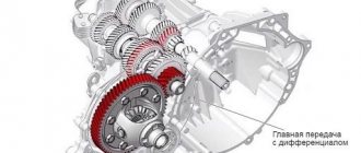
As a result, ball screws are a more expensive and reliable transmission option for machine tools and are suitable for moving heavy portals with high precision. Depending on the weight and design of the machine, you can use SFU1205, SFU1605/1610, SFU2005/2010 or the even more massive SFU2505/2510.
I hope the information was useful to you. Link to the CNA Mechanical Parts store Link to a cheaper option - ball screw SFU1204 Link to an affordable option TRR-12-3 with a plastic nut
Ball screw accuracy
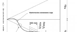
High-precision screws usually give an error of the order of 1-3 microns per 300 mm of travel, and even more accurately. Blanks for such screws are obtained by rough machining, then the blanks are hardened and ground to perfection. Three steps are strictly required, because... temperature treatment greatly changes the surface of the ball screw.
Hard-whirling is a relatively new metalworking technology that minimizes heating of the workpiece during the process, and can produce precision screws from a hardened workpiece. Instrumented ball screws typically achieve an accuracy of 250 nm per centimeter. They are manufactured by milling and grinding on ultra-precise equipment with control by specialized equipment of submicron precision. Lines for the production of lenses and mirrors are equipped with similar equipment. Such screws are usually made from Invar or other Invar alloys to minimize the error introduced by thermal expansion of the screw.
Application areas of ball screws
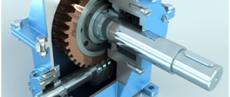
Ball screw in a CNC machine
The relative simplicity of the design and the ability to manufacture a ball screw with various characteristics expands the scope of its application. Nowadays, ball screws are integral components of homemade milling machines with numerical control. Well, the scope of application is not limited to this.
Due to their versatility, ball screws can be installed not only in CNC machines. Smooth running and virtually zero friction make them indispensable components in precision measuring instruments, medical installations, and mechanical engineering. Often, spare parts from these devices are taken to complete homemade equipment.
This was made possible thanks to the following properties:
- minimizing friction losses;
- high load capacity factor with small design dimensions;
- low inertia. The movement of the body occurs simultaneously with the rotation of the screw;
- no noise and smooth running.
However, the disadvantages of ball screws for CNC equipment should also be taken into account. First of all, these include the complex design of the housing. Even if one of the components is slightly damaged, the ball screw will not be able to perform its function. There are also restrictions on the speed of rotation of the propeller. Exceeding this parameter may result in vibration.
To reduce the axial clearance, the assembly is performed with interference. To do this, balls of increased diameter or two nuts with axial displacement can be installed.
Ball recycling systems
Bearing balls circulate in the thread channels of the nut and the raceways of the screw. If you did not guide the ball after the end of its journey, the balls would simply fall out of the nut outwards after reaching the end of the track, so ball screws use several more expensive systems for returning the balls to the beginning - recirculation systems.
The external system uses a metal tube that connects the inlet and outlet of the channel nut.
The outgoing balls fall into the tube, and pushed by subsequent ones, they follow to the entrance. The internal system involves cutting a similar channel inside the nut, the balls coming out of the nut are directed by a special lining into the drilled channel, and at the exit from the channel, a similar lining transfers the balls to the inlet of the treadmill. A very common option is when the balls circulate through several looped channels, where the return is ensured by a special plug. DARXTON
Characteristics of ball screws for CNC equipment
Sectional view of a ball screw
To select the optimal ball screw model for numerically controlled machines, you should familiarize yourself with the technical specifications. In the future, they will affect the performance of the equipment and the time of its maintenance-free operation.
The main parameter of ball screws for CNC machines is the accuracy class. It determines the degree of position error of the moving system according to the calculated characteristics. The accuracy class can be from C0 to C10. The movement error must be given by the manufacturer and indicated in the technical data sheet of the product.
| Accuracy class | C0 | C1 | C2 | C3 | C5 | C7 | C10 |
| Error at 300 µm | 3,5 | 5 | 7 | 8 | 18 | 50 | 120 |
| Error per screw revolution | 2,5 | 4 | 5 | 6 | 8 |
In addition, when choosing, you need to consider the following parameters:
- the ratio of the maximum and required motor speed;
- total thread length of the lead screw;
- average load on the entire structure;
- axial load value - preload;
- geometric dimensions - diameter of the screw and nut;
- electric motor parameters - torque, power and other characteristics.
These data must be previously calculated. It should be remembered that the actual characteristics of ball screws for CNC equipment cannot differ from the calculated ones. Otherwise, it will cause the machine to malfunction.
The number of revolutions of the balls in one circle will determine the degree of transmission of torque from the shaft to the housing. This parameter depends on the diameter of the balls, their number and the cross-section of the shaft.
The concept of accuracy class of ball screws
The general characteristic of ball screw accuracy, which is determined by the maximum errors of the instruments, is called their accuracy class. It is characterized by the following parameters:
- thread distance;
- geometric tolerance;
- level of surface smoothness;
- backlash;
- starting torque value;
- temperature operating conditions.
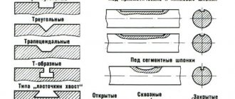
According to the production method, such transfers are:
- rolled. They are made by cold rolling, during which screw threads are made using special rolls. They belong to the transport group, since due to the graininess of the surface they allow movements that are not as smooth and accurate as precision pairs;
- polished. In such units, the screw grooves are hardened with multi-stage grinding. Used for high-precision devices. Belong to the precision group.
Precision rolling is also used, which involves a combination of both thread processing methods.
Depending on the application, there are 2 main groups of ball screws:
- transport (regular, with a gap). Such gears with low accuracy due to the presence of axial play are used for movements that are measured separately, without taking into account the angle of helical rotation. Examples: movements with low resistance (in door and valve drives), solving transport problems (in elevators), machine tools;
- positional (with interference, precision). Used when necessary to solve a high-precision problem. In this case, idling movement is not allowed. In such cases, transmissions require the presence of strong connections between nuts and assemblies. The dynamic load of the rod is reduced due to the strict dependence of screw speeds on nut movements.
Each of these groups has its own requirements, including accuracy class. Typically, positional gears have higher accuracy, while transport gears have a larger amount of backlash. Improve the performance of transport hubs with:
- creating preload. It involves applying a certain force to a pair to obtain the required level of axial rigidity. Helps reduce overall rod vibration and stabilize the nut axis in relation to the screw;
- increasing the diameter of the balls;
- using a double nut.
OST 2 R31-4-88 regulates the accuracy of ball screws in Russia, defining the following classes:
- for transport (T): T1, T3, T5, T7, T9, T10;
- for positional (P): P1, P3, P5, P7.
Foreign standards DIN 69051, Part 3 ISO 3408-3 provide for the following gear accuracy classes:
- for transport: C0, C1, C3, C5, C7, C10;
- for positional: C0, C1, C3, C5.
Basics of calculation
Average rotation speed and average load
If speed and load vary, life calculations should be made using average values of Fm and nm
For the average rotation speed nm, in case of speed changes, the following formulas apply:
where nm is the average speed, q is the fraction of time
For the average load Fm, in case of load changes, the following formula is used:
, where Fm – average load q – fraction of stroke or time at constant speed
For average load Fm, if rotation speed and load change, the formula applies:
where Fm is the average load q is the fraction of time nm is the average speed.
Nominal life
Resource L, expressed in number of revolutions:
L – resource, Fm average load, Сa – dynamic load
Resource expressed in hours Lh
Lh – life in hours L – life in revolutions nm – average rotation speed (rpm) ED – operating time (%)
Motor driving torque and external force
Drive torque Mta To convert rotary motion into reciprocating motion:
Drive torque Mte for converting reciprocating motion into rotary motion
where Mta – drive torque (Nm) Mte – resistance moment (Nm) F – working load (kN) P – pitch (mm) η – efficiency (about 0.9) η' – efficiency (about 0.8)
When using double preload nuts, the idle torque must be taken into account:
Drive power Pa
Pa – drive power Mta – drive torque n – rotation speed
Axial clearance and interference
Through interference, the ball screw gap is eliminated and rigidity increases. Moreover, the positioning accuracy of the ball screw is also improved. The tension of a single nut is achieved by installing balls of selected sizes. Double nut tension is created by pulling two nuts against each other.
Table 1 Combination of axial clearance and interference
| Symbol | 0 | 1 | 2 | 3 | 4 |
| Axial clearance | Yes | No | No | No | No |
| Preload | No | No | easy | average | high |
| % of dynamic maximum permissible load | — | — | ~3 | ~5 | ~7 |
table 2
| C.I. | S.K. | S.C. | DC | S.U. | D.U. | S.E. | |
| 0 | * | * | * | * | * | * | * |
| 1 | * | * | * | * | * | * | * |
| 2 | * | * | * | * | * | ||
| 3 | * | * | |||||
| 4 | * | * |
Combination of axial clearance 0
Table 3
| Spindle diameter | Axial clearance of screwed ball screw |
| 04-14 | 0.05 |
| 15-40 | 0.08 |
| 50-100 | 0.12 |