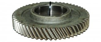
Bevel gear device
A bevel gear is a pair of bevel gears—gear wheels—that have been machined at a specified angle.
After processing, both gears receive a diameter that varies from base to top, a shape resembling a cone, which is why they got their name. The gear teeth are cut on the side surface; during operation, the bevel gears are mated with the side planes. Due to the peculiarities of their design, conical pairs are considered the most difficult to manufacture and assemble. In addition, they do not have the highest load-bearing capacity (for example, for a bevel gear, with other parameters being equal, it is 15% lower). However, in units and mechanisms where transmission of torque with angular displacement is necessary, there is no alternative to them. The element of the pair that transmits torque is called the drive (gear), and the one that receives the torque is called the gear (driven). The resulting angle of change in direction of rotation is equal to the sum of the angles of both bevel gears. Most often in machines and mechanisms there is an orthogonal conical pair that changes the direction of the torque at an angle of 90 degrees (2 x 45). The capabilities of a bevel gear are not limited to the ability to change the direction of the axis of rotation over a wide range of angles. With this design, you can also change the rotation speed (rpm) and power.
Introduction [edit]
Two important concepts in gearing are longitudinal surface
and
inclination angle
. The pitch surface of a gear is the imaginary toothless surface that you would get by averaging the peaks and valleys of individual teeth. The pitch surface of a conventional gear is cylindrical in shape. The gear pitch angle is the angle between the face of the pitch surface and the axle.
The most well-known types of bevel gears have an angle of less than 90 degrees and therefore have a bevel shape. This type of bevel gear is called external,
because the gear teeth point outward. The pitching surfaces of the meshed outer bevel gears are coaxial with the gear shafts; the vertices of the two surfaces are at the point of intersection of the shaft axes.
Bevel gears with an angle greater than ninety degrees have teeth facing inward and are called internal gears
bevel gears.
Bevel gears with an angle of exactly 90 degrees have teeth that point outward parallel to the axis and resemble the ends on a crown. That's why this type of bevel gear is called a ring gear
.
Face gears are mating bevel gears with the same number of teeth and axes located at right angles.
Helical bevel gears are those for which the corresponding ring gear has straight and inclined teeth.
Classification and parameters of bevel gears
The parameters by which bevel gears are classified are divided into geometric and mechanical. Geometric dimensions include linear dimensions and angle values of individual elements of parts forming a gear pair.
The mechanical parameters of the bevel gear pair include the following:
- transmission form (pure conical, linear conical, cylindrical conical);
- shape of the teeth of the gears used;
- number of stages (determined by the number of pairs actually working to transmit torque);
- rotation speed (number of revolutions per unit time)*;
- the direction of intersection of the axes (refers to the parameters specified by the project);
- load capacity (calculated when designing a gear transmission);
- the value of the gear ratio (determined by the number of teeth in the gears and allows you to calculate the speed for a gear pair);
- bending strength (applies mainly to shafts);
- the magnitude of the meshing force and the transmitted power (physical parameters included in the technical specifications and taken into account when designing a gear pair).
* According to the circular speed of rotation, bevel gears are divided into three main groups: low-speed (rotating at a low speed not exceeding 3 m/s), medium-speed (rotation speed up to 15 m/s) and high-speed (rotation speed above 15 m/s).
If the number of revolutions per unit time of the driving gear is greater than that of the driven gear, the gear is considered a reduction gear; If the driven bevel gear makes a large number of revolutions, the pair is recognized as a booster. The gear ratio also allows you to determine the gear class. For downshifts (reducers) it is less than one, for upshifts (multipliers) it is more than one.
Classification according to the shape of the tooth lines: A bevel gear may consist of a pair of bevel gears, which, according to the shape of the tooth lines, can be as follows:
- A. Straight bevel gears (the tooth line must pass through the top of the pitch cone);
- B. Gears with curved teeth;
- B. Gears with tangential teeth;
- D. Bevel gears with circular teeth (the angle of inclination of the teeth is acute, measured between the line of the tooth itself and the tangent to the selected point, the second name is the cone line).
To solve complex technical problems, spur bevel gears with spiral and radial cutting, gears with curved involute teeth (the surface of the drive tooth rolls along the generatrix of the driven wheel), and also with cycloid-shaped teeth are also used.
Basic geometric parameters
The construction of a kinematic diagram, technical characteristics, and methods of processing individual parts of these mechanisms are determined by the geometric shape of the individual elements. The main geometric parameters that are calculated during design are:
- angles of pitch cones (each wheel or gear);
- diameters of all elements (both shafts, drive and driven gears);
- outer circumferential gear module;
- the distance from the top of the cone to its generatrix (called the dividing distance);
- distance between axles;
- radial clearance of the bearings used;
- pitch diameter (it determines the size of the gear tooth);
- diameter of the recesses and the top of the teeth.
Read also: How to glue rubber to rubber tightly
For the convenience of carrying out calculations and understanding the mechanism of engagement, three types of end sections are introduced. These are sections in the outer, inner and middle part of each tooth.
Reducing the thickness of the teeth towards the tip results in a reliable engagement during movement. The angle of inclination towards the vertex determines the parameters specified during processing.
The line of teeth refers to the intersection of two straight lines. One is formed by the lateral surface of the tooth, the second is the edge of the dividing conical surface.
To improve performance characteristics - increase wear resistance, contact resistance, reduce jamming and better transfer of rotational energy to bevel gears, a method is used to equalize the specific slip coefficients.
For this purpose, they try to make the wheel and gear with the same displacement parameters, but with different signs. For example, for a gear a parameter is set with a plus sign, and for a wheel with a minus sign.
The basic geometric relationships are set at the stage of development of the entire bevel gear mechanism, transmission quality. Geometric parameters are calculated based on known relationships.
Advantages and disadvantages of bevel gears
Bevel gear pairs can effectively solve the problem of changing the torque transmission angle. Among the advantages of this design solution are:
- Possibility of changing the direction of the transmitted movement;
- Wide scope of application;
- The angle of transmission of torque from the drive wheel to the driven wheel can be set in a wide range;
- Effective implementation of transmission, conversion and increase in power of rotational motion between transmission axes located at an angle to each other;
- A large selection of technical solutions for the design of combined gear systems;
- High transmitted power (up to 5000 kW);
- Low maintenance, no problems during operation;
- High coefficient of efficiency (efficiency).
Among the disadvantages inherent in bevel gears is the difficulty of manufacturing gears with the required parameters, in particular, due to increased requirements for the accuracy of cutting teeth. Increased axial loads and bending loads on the shafts on which the gears are mounted are also noted. This is especially evident in mechanisms where the shafts are cantilevered. Disadvantages also include greater weight compared to other types of gears and high manufacturing costs. When designing and manufacturing systems with variable gear ratios, difficult-to-solve problems may arise; the rotation transmission process requires adjustment, and the overall rigidity of the structure is increased. And finally, among the disadvantages it is noted that the load-bearing capacity of a pair of bevel gears is 15% lower than that of a cylindrical gear transmission, and the load capacity is 20% lower.
CONTENT
- 1. Introduction
- 2 Types
- 3 Face gears
- 4 Bevel gear geometry 4.1 List of graphic symbols
- 6.1 Straight teeth
- 7.1 Materials used in the gear manufacturing process
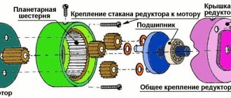
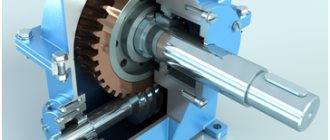
Manufacturing of bevel gears
The main elements of a bevel gear are gears - driving and driven. They are made primarily from steel on specialized machines using several technological processes.
Materials and technologies
The drive gear must have higher strength, therefore, in the manufacture of bevel pairs for gears, different grades of steel and different methods of chemical-thermal and heat treatment can be used. If alloy steel is used to make the gear, it may be surface sealed by cyanidation, carburizing, or nitriding. Carbon steel gears are case hardened.
Calculations and degrees of accuracy
In a bevel gear pair, the gear is initially characterized by its module (the length of the pitch circle per tooth) and the number of teeth. The diameters of the depressions and protrusions are determined from the table. The parameters of the tooth (thickness, height and length) and its elements - legs and heads, as well as the pitch diameter are subject to calculation. The coefficient of the width of the ring gear is used, and the angle of inclination of the oblique teeth is determined. The profile angle, overlap and displacement coefficients, and engagement lines are also taken into account.
For bevel gears, four degrees of accuracy out of 12 existing ones are accepted, each of which is determined by the speed of transmitted rotation. The permissible circular speeds are as follows:
- no more than 3 m/s for the ninth degree;
- from 3 to 7 m/s for the eighth degree;
- 7-10 m/s for the seventh;
- up to 20 m/s up to degree 6 inclusive.
Manufacturing methods
Milling and gear cutting operations do not allow achieving the required accuracy, so they are usually supplemented by rolling. Running is a method of processing a gear in which the allowance on its side surfaces is cut off by the cutting edges of the tool directly during the main cutting movement of the workpiece. After running-in, the pair is placed on a special stand where the bevel gears are ground in. And finally, the final stage is the process of hardening the teeth.
Currently, the equipment of modern metalworking enterprises allows us to produce conical pairs of any size, type and technological profile. The quality of finished products is checked both visually and in laboratory conditions using advanced diagnostic and scanning methods.
Types[edit]
Bevel gears are classified into different types based on geometry:
- Straight bevel gears
have a tapered longitudinal surface and the teeth are straight and tapered towards the tip. - Spiral bevel gears
have angled teeth that provide smooth, smooth tooth contact. - Zerol bevel gears
are very similar to bevel gears, but the teeth are curved: the ends of each tooth are coplanar with the axis, but the middle of each tooth runs in a circle around the gear. Zerol bevel gears can be thought of as helical bevel gears that also have curved teeth, but with a zero helix angle so the ends of the teeth line up with the axle. - Hypoid bevel gears
are similar to helical bevel gears, but their pitching surfaces are hyperbolic rather than conical. The gear can be offset above or below the center of the gear, resulting in larger gear diameter, longer life and smoother meshing. If the beveled surface is made parallel to the axis of rotation, the configuration resembles a worm drive. Hypoid gears are widely used in rear axles of cars.
Hypoid bevel gear
Applications [edit]
Bevel gear has many varied applications such as locomotives, shipbuilding, automobiles, printing machines, cooling towers, power plants, steel mills, railway track inspection machines, etc.
For examples, see the following articles:
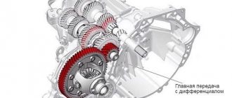
- Bevel gears are used in differential drives
, which can transfer power to two axles rotating at different speeds, such as on a rotary car. - Bevel gears are used as the main mechanism of a hand drill
. When the drill handle is turned in a vertical direction, the bevel gears change the rotation of the chuck to horizontal. Hand drill bevel gears have the added benefit of increasing chuck rotation speed, allowing you to drill into a wide range of materials. - The gears in
bevel
gear
planer allow for minor adjustment during assembly and allow some movement due to deflection under operating loads without concentrating the load on the end of the tooth. - Spiral bevel gears are important components of rotorcraft
. These components are required to operate at high speeds, high loads and a high number of load cycles. In this application, spiral bevel gears are used to redirect the shaft from a horizontal gas turbine engine to a vertical rotor. Bevel gears are also used as speed reducers.
Bevel gears in a grain mill in Dordrecht. Note the wooden toothed inserts on one of the gears.
Teeth [edit]
There are two problems associated with tooth shape. One of them is the cross-sectional profile of an individual tooth. The other is the line or curve along which the tooth fits onto the face of the gear: in other words, the line or curve along which the cross-sectional profile is projected, forming the actual three-dimensional shape of the tooth. The main effect of both the cross-sectional profile and the tooth line or curve is the smoothness of the gears. Some result in smoother gears than others.