- What are gears
- Types of gears
- Gear design
- Main settings
- Circle diameters
- Gear modules
- Calculation of parameters
- Application
- Gear and gear - differences
- Features of gears and gears
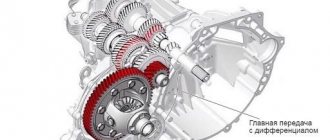
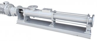
Gear drives are very widely and productively used in the designs of modern machines, mechanisms and devices. Vehicles, power plants, lifting devices, aircraft installations, agricultural machines, precision instruments - all of them contain one or another version of the gear wheel. In technology, gears are used to distribute rotational motion between the axes of shafts, which can be parallel, crossed or intersecting. Also, with the help of such a transmission, it is easy to convert rotational motion, for example, into translational motion, or to realize effective conversion of torque and shaft speeds. Thanks to the latter property, they are used in various types of gearboxes or multipliers, as well as gearboxes.
The main advantages of this method of power transmission are high efficiency; compact design; smooth operation; accuracy; durability; reliability; the ability to transmit force using any angle, gear ratio (up to several thousand) and a wide range of speeds (up to 150 m/s). These qualities determined the spread of the use of gears in technology. Negative aspects include the technological complexity of production; demands on precision processing, materials and processing equipment. The choice of material for a gear is one of the most important criteria for reliability and durability in its further operation. The rigidity of the structure, which ensures high efficiency of the transmission, unfortunately, does not allow it to withstand high values of dynamic loads, which often cause destruction of the mechanism. In addition, these transmissions are characterized by increased noise, which can be reduced by increasing the quality and precision in the production of products.
What are gears
In general, a gear, or cogwheel, is the main part of the transmission of the same name, and has the form of a disk with teeth located on a cylindrical or conical surface. With the help of these teeth, during the rotation process, the wheels engage with each other, which makes it possible to transfer torque from one shaft on which the wheel is located to another. When a tooth of a gear wheel rotates, it pushes the tooth of another wheel connected to it, which, as a result, also begins to perform a rotational movement.
The mating gear train must always consist of two types of elements: driving and driven. In this case, the driving wheel, by definition, is the wheel that transmits (communicating) rotation, the driven wheel is the gear that has a large diameter with a large number of teeth and causes rotation. In most cases, a pair of gears is used, one with a large number of teeth and the other with a smaller number. Sometimes the element that has fewer teeth is considered a gear, while the one with more teeth is considered a wheel.
Excerpt characterizing gear transmission
“Yes, that’s nice,” Rostov said, smiling. But Boris, noticing that Rostov was about to laugh at Berg, skillfully deflected the conversation. He asked Rostov to tell us how and where he received the wound. Rostov was pleased with this, and he began to tell, becoming more and more animated as he spoke. He told them his Shengraben affair exactly as those who participated in them usually talk about battles, that is, as they would like it to have happened, as they had heard from other storytellers, as it was more beautiful to tell, but not at all the way it was. Rostov was a truthful young man; he would never deliberately tell a lie. He began to tell with the intention of telling everything exactly as it was, but imperceptibly, involuntarily and inevitably for himself, he turned into a lie. If he had told the truth to these listeners, who, like himself, had already heard stories about the attacks many times and formed a definite concept of what the attack was, and expected exactly the same story - or they would not have believed him, or, even worse, they would have thought that Rostov himself was to blame for the fact that what usually happens to storytellers of cavalry attacks did not happen to him. He couldn’t tell them so simply that they all rode at a trot, he fell off his horse, lost his arm and ran with all his might into the forest away from the Frenchman. In addition, in order to tell everything as it happened, it was necessary to make an effort on oneself to tell only what happened. Telling the truth is very difficult; and young people are rarely capable of this. They were waiting for the story of how he was burning all over the fire, not remembering himself, how he flew into the square like a storm; how he cut into it, chopped right and left; how the saber tasted the meat, and how he fell exhausted, and the like. And he told them all this. In the middle of his story, while he was saying: “You can’t imagine what a strange feeling of rage you experience during an attack,” Prince Andrei Bolkonsky, whom Boris was waiting for, entered the room. Prince Andrei, who loved patronizing relations with young people, flattered that they turned to him for protection, and well disposed towards Boris, who knew how to please him the day before, wanted to fulfill the young man’s desire. Sent with papers from Kutuzov to the Tsarevich, he went to the young man, hoping to find him alone. Entering the room and seeing an army hussar telling the military adventures (the sort of people whom Prince Andrei could not stand), he smiled affectionately at Boris, winced, narrowed his eyes at Rostov and, bowing slightly, sat down tiredly and lazily on the sofa. It was unpleasant for him that he found himself in bad society. Rostov flushed, realizing this. But it didn’t matter to him: it was a stranger. But, looking at Boris, he saw that he too seemed ashamed of the army hussar. Despite the unpleasant mocking tone of Prince Andrei, despite the general contempt that, from his army combat point of view, Rostov had for all these staff adjutants, among whom the newcomer was obviously counted, Rostov felt embarrassed, blushed and fell silent. Boris asked what news was at headquarters, and what, without immodesty, had been heard about our assumptions? “They will probably go forward,” Bolkonsky answered, apparently not wanting to talk more in front of strangers. Berg took the opportunity to ask with particular courtesy whether, as was heard, they would now issue double forage to army company commanders? To this, Prince Andrei answered with a smile that he could not judge such important state orders, and Berg laughed joyfully. “We’ll talk about your business later,” Prince Andrei turned again to Boris, and he looked back at Rostov. – You come to me after the review, we will do everything we can. And, looking around the room, he turned to Rostov, whose state of childish insurmountable embarrassment turning into embitterment he did not deign to notice, and said: “It seems you were talking about the Shengraben case?” You were there? “I was there,” Rostov said angrily, as if by doing so he wanted to insult the adjutant. Bolkonsky noticed the hussar’s condition and found it funny. He smiled slightly contemptuously. - Yes! there are many stories about this matter now! “Yes, stories,” Rostov spoke loudly, suddenly looking wildly at Boris and Bolkonsky, “yes, there are many stories, but our stories are the stories of those who were in the very fire of the enemy, our stories have weight, not stories of those staff guys who receive awards without doing anything. – Which one do you suppose I belong to? – Prince Andrei said calmly and smiling especially pleasantly. A strange feeling of embitterment and at the same time respect for the calmness of this figure was united at this time in Rostov’s soul.
Types of gears
All gears, the types of which are as numerous as the options for their application, are divided into main types according to the location of the shaft axes and the geometry of the teeth. There are cylindrical, bevel, worm, and screw gears. In practice, based on the shape of the tooth profile, involute and circular gears are distinguished, and according to their location, spur and helical types of gears are distinguished.
For the parallel case of shaft axes, cylindrical gears are used:
- straight teeth;
- with circular teeth;
- chevron;
- helical.
Bevel gears are suitable for intersecting axes:
- with curved teeth;
- helical;
- with zero tilt angle;
- straight teeth.
When the axes intersect, then gears are used:
- spiroid;
- hypoid;
- screw;
- worm-type
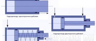
Cylindrical gears have become the most widespread among machines and mechanisms. They are characterized by ease of manufacture, reliability, and small dimensions. Bevel, worm and helical types of gears are used only when the layout of the machine imposes special conditions. Cylindrical gears are divided into two essential types: external and internal gearing. In the first embodiment, the externally geared wheel and gear rotate in directions that are opposite to each other. In the second, the internal gear wheel and the external gear perform rotational movement in a directional direction. There is also a rack and pinion transmission - in it, a rack with teeth mates with an externally meshed gear.
Helical cylindrical wheels have teeth located at an angle to the axis. The mating wheels have the same tooth inclination, but different directions. One will tilt to the right, while the other will tilt to the left. The presence of an inclination makes it possible to transmit larger loads compared to straight teeth, promotes smooth engagement of the teeth and reduces noise.
Chevron wheels are a pair of connected wheels with oblique teeth that have an equal angle of inclination, but are located oppositely: one with a right inclination, the second with a left inclination. This allows the axial forces to be balanced, thereby reducing the load on the bearing. Wheels may have a groove in the middle. Wheels without a groove are more durable, but difficult to manufacture.
Helical cylindrical gears, in turn, are used to rotate shafts when their crossing angle lies in the range from 0 to 90 degrees. They are similar to helical gears, but the helical gear has a point contact rather than a linear contact like a helical gear. The direction of inclination of the teeth of all such mating wheels is the same. Point contact of teeth causes increased wear, and as a result they are used only under light loads.
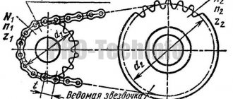
Rack and pinion gears are made up of gears and racks, which also have teeth. Rotating, the cylindrical wheel moves the mating rack along a straight line perpendicular to the axis of the wheel. In this way, the movement turns from rotational to translational. This type of transmission can be used with both oblique and straight teeth.
Straight bevel gears have teeth that intersect the axes of these wheels. The conical arrangement allows rotation of intersecting or crossing axes. The teeth can also be oblique, i.e. tangent to the circle. The angle of inclination of the teeth of such wheels is no more than thirty degrees. Supplying bevel wheels with teeth with a zero angle of inclination provides the first with low axial and radial loads and makes it possible to use plain bearings. These qualities make transmissions using such wheels compact and inexpensive to manufacture.
The use of curved teeth for bevel gear applications dramatically reduces gear noise and increases strength. Bevel gears of this kind always have at least two teeth in mesh, which gives them the ability to withstand a load that is 30% higher than identical spur gears and wheels with zero inclination.
Hypoid gears are similar to bevel gears, but the axis of the drive gear is offset higher or lower relative to the axis of the wheel it drives. In such gears, the gears have a greater tooth angle than the wheels. In this case, the normal pitch of the pinion and gear will be the same, but the face pitch will be larger for the gear. The hypoid transmission is not characterized by pure rolling or sliding; all its points are subject to sliding. This gives it smoothness and increased noiselessness. In addition, grinding in occurs faster and with better quality. The downside is that the presence of sliding causes increased wear on the surface of the teeth, which requires the use of specialized oils for such gears.
Cylindrical worm gears have a worm having the geometry of a cylinder, on which turns are cut, running along the direction of the helix. The worm wheel must have concave teeth. The linear contact of such teeth ensures the transmission of large loads. The slip of worm gears is much higher than that of other gears. In a globoid gear, the worm has a concave shape. This feature allows a larger number of teeth to participate in the engagement process, which increases the magnitude of the loads transmitted by such transmission.
Spiroid gears occupy an intermediate place between worm and hypoid variants. Unlike a worm gear, in a hypoid gear the worm is cone-shaped and engages with a wheel on which the teeth are located on the end side.
Tooth shape
Gears vary in tooth profile and type . Based on the shape of the tooth, involute, circular and cycloidal gears are distinguished. The most commonly used are involute gears. They have technological superiority. Cutting teeth can be done with a simple rack and pinion tool. These gearings are characterized by a constant gear ratio, independent of the displacement of the center-to-center distance. But at high powers, disadvantages appear due to the small contact patch in the two convex surfaces of the teeth. This can lead to surface damage and chipping of surface material.
In circular gearing, the convex teeth of the gear mesh with the concave wheels and the contact patch increases significantly. The disadvantage of these gears is that friction appears in the wheel pairs. Types of gears:
- Straight teeth. This is the most commonly used type of wheelset. Their contact line is parallel to the shaft axis. Spur gears are relatively cheap, but their maximum transmitted torque is less than that of helical and chevron wheels.
- Helical teeth. Recommended for use at high speeds, they provide smoother running and reduced noise. The disadvantage is the increased load on the bearings due to the occurrence of axial forces.
- Chevron. They have the advantages of helical wheel pairs and do not load the bearings with axial forces, since the forces are directed in different directions.
- Curvilinear. Used for large gear ratios. Less noisy and better at bending.
Straight-toothed wheel pairs are the most common. They are easy to design, manufacture and operate .
Gear design
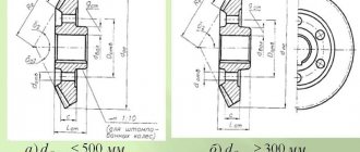
Metal gears, the design of which is sometimes quite complex, have a variety of designs, but they can be divided into three main components: the ring with teeth, the hub and the wheel itself. The ring gear is the main component and bears the brunt of the load. The teeth have different geometries. The outer part of the tooth is the apex, the side parts adjacent to it are the head of the tooth. The inside of a tooth is called its pedicle. The space between the two nearest legs forms the wheel cavity. To attach a gear or wheel to a shaft, a hub is located in the center of the disk, which has a through hole, the shape of which directly depends on the cross-section of the shaft: it can have the shape of a cylinder, square or any other polygon. In the case of cylindrical shafts, the hub often has a so-called keyway In order to save materials and weight of the wheel, its disk has a thickness that is smaller than the thickness of the rim and hub. Often various holes are also made in the disk for these purposes.
Bevel gear
In conditions where torque from the source to the consuming node must be delivered with an angular displacement, intersecting shafts are used. Their axes are most often at an angle of 90 degrees. In such cases, bevel gears are usually used.
It is called so because of the design features of the gear pairs. They have the shape of a cut cone and are mated with their lateral planes, on which the teeth are cut. In profile, they are higher at the base and decrease towards the top.
The ring gear can have a straight, tangential or curved cut. If the profile is made in the form of a helical spiral, and the shafts, in addition to intersection, also have an axial displacement, then such a bevel gear is called hypoid. It has a smooth running and low noise level, but has an increased tendency to jam, so special lubricants are used for it.
Compared to spur gears, bevel gears can provide only 85% of their load-bearing capacity. In terms of manufacturing and assembly technology, they are the most complex. However, the ability to transmit torque with angular displacement makes them indispensable in complex units and mechanisms.
Main settings
To ensure the possibility of designing efficient gears, the dimensions of wheels and gears, as well as their strength and weight and size characteristics, are described by special parameters, the values of which are well standardized by GOST. Thus, the involute profile, which is the basis for the tooth section of the vast majority of wheels, is characterized by the engagement module and the number of teeth on the wheel or gear. Quite often, involute gears, having the same diameter, can have significantly different values of these quantities. The circumferential module, which serves as the main characteristic for teeth, according to the standard can have values in the range from 0.05 to 100 mm. The main parameters of the geometry of various gears are the following diameters: initial, main and pitch. The pitch of a gear is the total distance between the width of the tooth and the root. Another important parameter is the radius of the wheel. The radii of gear wheels are divided into: radius of the vertex circle, radius of the pitch circle, radius of the main circle, radius of the valley circle.
Let's summarize
Design drawings and diagrams for gears of various configurations are mainly the same for oblique and spur versions. The main differences arise in strength calculations. Graphic displays use characteristics based on typical overall dimensions of gears. Among the assortment presented on the market, it is quite possible to select a gear with the necessary characteristics and strength indicators.
Sources
- https://mehmanxona.ru/tehnologii/vidy-shesterenok.html
- https://novoe-info.ru/chto-takoe-modul-shesterni/
- https://MechPrivod.com/market/zubchataya_shesterenka/shesterenka_zubchataya_cilindricheskaya/
- https://novoe-info.ru/kak-nayti-modul-zubchatogo-kolesa/
- https://doctordent.su/pulpit/kak-opredelit-modul-zuba-shesterni-po-diametru.html
- https://FB.ru/article/429020/modul-shesterni-vidyi-opredelenie-standartnyie-pokazateli
Circle diameters
A gear wheel is described by several circles, which are important characteristics of their geometry. Thus, the diameter of the vertices gives the maximum dimensions of the gear. The diameter of the circle of the depressions is opposite to it. By calculating the difference between these two values and dividing it in half, we get the total length of the tooth. An important parameter is the diameter of the pitch circle, which has the formula d=pz/3.14; from it you can determine the circumferential pitch p of the teeth located on the wheel, otherwise called the pitch of engagement, which has a geometric meaning of the part of the length of this circle per tooth. In general, the diameter of the pitch circle separates the height of the heads and the height of the legs of the teeth. It also sets the curve, which is the necessary basis for constructing the involute itself, and is used to construct the profile of wheel and gear teeth required for a specific task.
Gear modules
To simplify the calculations of the elements used for gearing, a standardized GOST value called the module was introduced for gears. The gear module is the part of the diameter of the existing gear pitch circle that falls on the tooth: m=d/z. Thus, the number of teeth of a wheel, its own pitch diameter and its module are mutually influential. The module can be written as the ratio of the wheel engagement pitch and the Pi number: m=d/3.14. When the load transmitted by gears is small, it is better to use small modules. The small module gives longer service life and simplifies gear processing. In this case, there will be more teeth on the pitch diameter, which means that engagement will occur with a larger number of them, which will reduce the load on individual gear teeth. Spur gears have only one module, helical gears have two: normal and circumferential. The first one is used in calculations.
Helical gears
They are used most widely, since the technology for manufacturing wheel sets is relatively simple and proven. A spur gear is used to transmit torque between shafts located in parallel planes. They differ in the shape of the teeth: straight, oblique and chevron. In rare cases, when crossing shafts and minor loads, a screw profile is used.
Straight teeth are the most commonly used. They are used to transmit torque with light or medium loads, as well as in cases where there is a need to shift the wheels during operation along the shaft axis. Oblique teeth are used for smooth running. They are used for critical mechanisms and under increased loads. The chevron profile (two rows of helical teeth along the edges, arranged in a herringbone shape) is characterized by a high balance of axial displacement forces, which is a disadvantage of helical wheel pairs.
Spur gears can be of open or closed type. In the latter case, the teeth of one of the wheels are located not on the outer, but on the inner surface of the circle.
Calculation of parameters
For all gears, the engineering calculation of their parameters is a complex task, during the solution of which the design of the entire transmission is taken into account. First you need to decide on the number of teeth and the gearing module required for the task. To select the latter, the parameters of strength and expected service life of the wheels are required; the material from which it will be made. Based on these data, the minimum possible value of the engagement modulus in a given problem is calculated, which is then reduced to standardized values found from the corresponding tables. The gear ratio is calculated using the formula u=z2z1, where z2 is the number of wheel teeth, and z1 is the number of teeth on the gear. It allows you to understand how many teeth are needed on the wheels to be mated. Knowing the modules and the resulting number of teeth for all wheels and gears, further calculations of the dimensions of the required parts can be made using a standard method for their calculations.
Maintenance and billing
Maintenance consists of inspecting the mechanism, checking the integrity of the teeth and the absence of chips. Checking the correct engagement is done by applying paint to the teeth. The size of the contact patch and its location along the height of the tooth are studied. Adjustment is made by installing spacers in the bearing units.
First you need to decide on the kinematic and power characteristics necessary for the operation of the mechanism. The type of transmission, permissible loads and dimensions are selected, then materials and heat treatment are selected. The calculation includes the selection of the engagement module, after which the displacement values, the number of gear and wheel teeth, the center distance, and the width of the rims are selected. All values can be selected from tables or using special computer programs.
The main conditions necessary for long-term operation of gears are the wear resistance of the contact surfaces of the teeth and their bending strength.
Achieving good performance is the main focus in the design and manufacture of gear mechanisms.
Application
Each type of transmission has its own advantages and disadvantages. Cutting spur gears is a fairly simple technological process, which is why they are widely used in industry. Helical and spur gears are used in tractors, machine tools, and vehicle gearboxes. Due to their compactness and strength, cylindrical wheels using internal gearing have found themselves in aircraft, automobile transmissions, gearboxes, splined joints and complex planetary gears, which are famous for their particularly low weight and overall dimensions. At the same time, they provide high gear ratios and significantly reduced noise levels during operation. Chevron wheels, being labor-intensive to manufacture, are used in large gearboxes and their repair, where smooth and silent transmission of significant loads is required. Bevel wheels with zero inclination and their straight-toothed analogues, having high compactness and low manufacturing costs, are used in differentials of cars and machine tools. Curved teeth provide bevel wheels with special strength and low noise, so they can be found in critical and high-speed gears. They are used almost everywhere: from airplanes to tractors. Hypoid gear pairs can be made with high gear ratios (up to 100:1) and are often used in metal-cutting equipment.
Materials for production
The main material for making wheelsets is steel. The gear must have higher strength characteristics, so wheels are often made of different materials and subjected to different thermal or chemical-thermal treatments. Gears made of alloy steel are subjected to surface hardening by nitriding, carburizing or cyanidation. For carbon steels, surface hardening is used.
The teeth must have high surface strength, as well as a softer and more viscous core. This will protect them from breakage and surface wear. Wheel sets of low-speed vehicles can be made of cast iron. Bronze, brass and various plastics are also used in various industries.
Gear and gear - differences
The main parts in a gear drive are the gear and pinion. They are used in many industrial units and machines. Many people believe that a gear and a gear are the same part and there are no differences between them. Specialists who are closely associated with industry and mechanical engineering do not think so and I assure you that these are different parts, although they essentially perform the same function of transmitting rotational motion. Let's look at the main points on this issue.
Links
Straight-line Slider (crosshead) • Crank-rod • Faceplate-rods • Pumping bearing • Scotch • Rack and pinion gear • Screw drive • Winch (Gate) • Sarrus • Lipkin - Posselier …approximately Watt • Heuken • Chebyshev • Klann • Jansen Progressive Parallelogram Complex movement Cam • Eccentric • Ellipsograph • Four-link • Grab
Features of gears and gears
Externally, a gear wheel and a gear are similar in the form of a disk with teeth located on it. Their location can be either on a conical or cylindrical surface. The main task of these parts is to transmit torque. In order to receive and transmit torque, you need a counter gear, that is, a pair. We discussed above that there is a driven part and a leading one. Movement begins from the driving part and further transmission of torque to the driven part begins. This key point is the difference between a gear and a gear; the driving part is a gear, and the driven part is a gear. It turns out that the whole difference between them is what role the part plays in the mechanism.
Note that when two gears operate, the wheel that has the greater number of teeth is called a gear. In GOST 16530-83 there is an explanation that gear and gear are synonymous words, gear is the main and driving gear. There are specialists working in certain areas of industry and mechanical engineering who clearly distinguish the difference between a gear and a gear. They are convinced that making gears is one thing and making gears is another because there are differences between them.
Types of motion transmission
The engine that generates energy and the final unit that consumes it often differ in characteristics such as rotation speed, power, and angle of application of force. In addition, one source of rotational energy can be used to drive several different components or assemblies at once. To ensure the delivery of torque under such conditions, intermediate modules are needed that would transmit this force with minimal losses.
If, as a result of such distribution or transformation, the revolutions of the drive shaft become greater than those of the driven shaft, then it is customary to talk about a reduction gear. In this case, the loss of speed is compensated by an increase in the load on the driven axle and an increase in the power of the consuming node. In the case where an increase in the number of revolutions is ultimately observed, such a gear will be an overdrive. Accordingly, this will be accompanied by a decrease in force on the driven shaft.