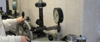
Pressure gauges (devices for measuring pressure), like all precision instruments, must be monitored and verified. This is important because they are used on units that pose a danger if used incorrectly: gas cylinders, boilers, production equipment. The serviceability of the pressure gauge is monitored using specialized metrological systems; It is important that the procedure is carried out by a competent specialist. The pressure gauge is verified by an accredited organization in laboratory conditions using certified standards.
Methods for installing pressure gauges
Its installation can only be carried out on an object where the pressure has been relieved. The device must be installed in the working position. As a rule, it is described in the instructions for its use. It specifies how it should be installed on the pipeline and installation tolerances. You can install it using a wrench. The tightening torque should not exceed 20 N×m. Overloading the housing is unacceptable.
In practice, several installation methods are used:
- straight;
- using a three-way valve;
- using an impulse tube.
Types of devices
Since the scope of application and operating conditions are different, the pressure gauges are also different. For heating there are 5 types:
- Spring. The most popular models that are used in domestic and industrial environments. There is a spring inside. Under pressure, it transmits force to the dial hand.
Membrane. These pressure gauges are also in good demand. The principle of operation is similar to spring ones, only an elastic plate or membrane box is used as a sensing element.- Liquid. There is a tube running inside them that operates on the basis of communicating vessels. When a load is applied to one vessel, the liquid in the other rises to a certain height. Such devices are very accurate, but are more suitable for laboratory research.
- Electric contacts are used not only for measuring pressure. They can be connected, for example, to a circulation pump to control it. When the arrow reaches the desired value, the circuit will close or open. This is especially useful in industrial settings.
- Differential. They consist of several chambers that are separated from each other by a sensitive element. Usually these are portable devices with the help of which the pressure difference is calculated.
If we talk about working conditions, pressure gauges are also divided into:
- general technical;
- exemplary;
- self-writing;
- railway;
- ship's
Only general technical ones are suitable for heating. The rest are either too accurate or contain additional functions that are not needed in everyday life.
Liquid pressure gauge
It is a curved glass tube with divisions in millimeters of mercury. It is half filled with water.
The principle of operation is based on the difference in levels. When one end of the tube remains open and the opposite end is connected to the measuring point, the liquid begins to move. In the first it goes down, in the second it goes up. The difference relative to the zero mark will be the value that we need.
Spring pressure gauge
In demand in a variety of fields. It is valued for its compactness, versatility and durability. Operation is possible in the range from 0.1 to 4 thousand bar.
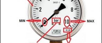
Structurally similar to a thermometer. The built-in sensing element automatically responds to changes in the environment. The free end is connected to the fitting. The closed part of the tube communicates with the transmitting sector. It consists of a liner, a gear, a pointer and a scale. The latter is marked according to pascals or bars. The mechanism is built into the body.
The measurement process can be described as follows. The tube takes pressure and tends to straighten as the outer and inner areas collide. The open part transmits the force of the arrow, and it changes position.
Electric contact pressure gauge
An electric contact pressure gauge, or ECS for short, is designed not only to measure pressure, but also to send a signal to external devices.
Special contacts located between the arrows transmit the discharge to one of the parts. The circuit closes, thereby affecting the slave device.
Diaphragm pressure gauges
Pressure gauges with a membrane are part of filters, valves and other flow meters involved in the maintenance of various samples.
The word “deformation” is often added to the name, since the parameters are read by pressing or straightening the membrane.
Installation method on a three-way valve
If it is planned that when checking data it will be necessary to switch the device to atmospheric pressure, then, as a rule, a three-way valve is installed in front of it. It is used to supply atmospheric air. In addition, the installation of pressure gauges with a three-way valve and a siphon tube allows the device to be replaced without interrupting the supply of the working medium. In addition, the presence of such a crane allows you to perform various works when stopping its work is not necessary.
What it is?
A pressure gauge is a device for measuring pressure. When the heating pressure drops, the equipment stops working.
Moreover, air begins to accumulate. If the pressure exceeds the norm, this can lead to a rupture at some point in the system.
To set up equipment and troubleshoot problems in a timely manner, you must always monitor the indicators. This is precisely what pressure gauges are used for. They are used not only in heating, but in general in any systems where pressure needs to be controlled.
They look quite simple: a plastic case, a dial and a connecting tube. There is a membrane or spring inside. When pressure is applied to them, they are deformed, and the needle deviates to a certain point.
Electronic options are less common, but they are also installed. Bars, atmospheres or pascals are used for measurement. 1 bar = 0.99 atmospheres, but pascals are too many, so megapascals are more often used. 1 megapascal = 10 bar.
Installation method using an impulse tube
In addition to the above-mentioned installation methods, they also use installation using an impulse tube. It is necessary to protect the measuring device mechanism from pressure drops.
To install a measuring device in this way, it makes sense to first install the adapter, then the tube, the three-way valve, and only after that can the sensor itself be installed.
An impulse tube is used when the working medium, for example steam, has an operating temperature that exceeds the standards for the characteristics being measured. The presence of the tube prevents contact between the working medium and the pressure meter.
Why is it installed?
Measuring instruments are installed to monitor the condition of the system. The pressure in the pipelines should not exceed a certain threshold value. At the same time, it must be sufficient to operate various devices.
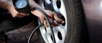
To operate a shower with hydromassage, you need a pressure of 3-4 bar, a washing machine - about 0.5 bar, and a reverse osmosis filter - 2-6 bar.
Installation locations:
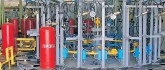
- pumping stations;
- boiler rooms;
- railway transport, automobiles, aircraft and water vessels;
- pressure pipelines;
- water heating devices;
- filtration systems.
Pressure gauges are purchased for personal use, in order, for example, to periodically monitor the pressure of the water entering the mixer.
They are permanently installed at pumping stations next to hydraulic accumulators and pressure switches to automatically turn the pump on and off. Often pressure gauges are part of automation units.
Installation and removal rules
To ensure stable operation of the pressure gauge and reduce the risk of its breakdown, follow certain rules:
- The installation of pressure gauges must be carried out in such a way that it would be quite easy to take measurement results and carry out routine maintenance and repairs.
- The rules define a number of conditions that determine the maximum dimensions of the distances between the measuring device and the walls of the room in which the device is installed.
- If the pressure gauge is mounted at a height of 2 to 3 meters, the diameter of the housing must be no less than 160 mm. It is unacceptable to install pressure gauges at a height of more than three meters. This is defined in the requirements of regulatory documentation.
- To carry out the checks of measuring instruments and equipment prescribed in the regulatory documentation when using the instruments, a three-way valve must be installed in the installation structure. Its installation location should be between the pressure gauge and the pipe (vessel).
- When installed in conditions where it may be influenced by external external factors, for example, precipitation or high temperature, it is necessary to provide additional protection. For this purpose, so-called buffer elements, siphons and other products are used. The efficiency of the installed measuring equipment depends on how well it is protected from external influences.
- To prevent freezing of the measuring instrument, they are provided with thermal insulation.
- When connecting, it is necessary to vent any gas that has entered the system. To do this, slightly tighten the fixing nut on the fitting.
- Pressure gauges that have not been verified and do not have a seal or appropriate seal on the body should not be allowed to be used for operation in networks. If the verification period has expired, or during operation it turns out that the operation differs from the standard one, then it must be removed and sent for diagnostics and repair. If damage appears on the meter body, or a crack appears on the glass, then such a device cannot be used and must be disposed of.
- Damaged sensors are dismantled and transferred to a certified laboratory for repair work. If such a pressure gauge cannot be restored, then it is disposed of.
Once a year or once every five years?
The frequency of checking pressure gauges is indicated in their technical data sheet. It depends on the design and model of the device. Typically, the timing of calibration of pressure gauges is once a year for older models and once every 2-5 years for models developed after 2000. This is due to the fact that new devices are more technologically advanced.
The frequency of checking pressure gauges is set by the manufacturer and must be strictly observed if the organization falls under the GROEI. The verification period may be shorter if the scope of application of pressure gauges falls under various safety regulations or internal regulations of the enterprise.
Installation features
The pressure meter must only be mounted in a vertical position. This should ensure normal reading of the received data. The meter scale can be tilted at an angle of no more than 30°. The sensor must be illuminated and protected from exposure to sunlight and low temperatures.
After the device is installed and the system is ready for operation in normal mode, then to ensure the safety of the device, it is not advisable to immediately load the installed measuring equipment. It is advisable to increase the pressure gradually, without any jumps and without crossing the established boundaries.
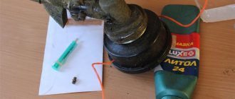
When installing the meter in place, it is necessary to ensure that the connection between the meter and the fitting in which it is mounted is tight. For this, various sealing materials are used, for example, FUM tape or thread. To increase reliability, sealing materials can be treated with a sealant. All materials used must comply with operating conditions, that is, if superheated steam is used in the pipeline system (minimum temperature 130 °C), then installing FUM tape designed for an operating temperature of 95 °C is unacceptable. By the way, some installation organizations, in the old fashioned way, use tow as an insulating material; it should be noted that this is not encouraged.
Operating principle
In a deformation (spring) pressure gauge, water enters a curved tube made of copper alloy. The water pressure causes the tube connected to the mechanism to deform, which causes the needle to turn.
Pressure gauges with a single-turn spring are designed for pressures up to 100 atm. To measure higher pressures, springs with several turns twisted into a spiral or screw are used.
There are devices in which a thin two-plate membrane is installed instead of a tube. They are suitable for viscous or contaminated solutions, withstand strong vibrations, but are sensitive to temperature fluctuations.
How is it different from a sensor?
A pressure gauge is a device that makes it possible to determine pressure at any time.
It can be equipped with a sensor, thermometer and other additional elements. The sensor is part of the warning system. It only works at a certain pressure value. The sensor readings are converted into a signal that allows you to adjust the operation of the system in automatic or manual mode.
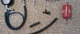
Instructions for making the device yourself
In order not to spend money on buying a ready-made fuel pressure gauge, you can make it yourself. It is necessary to assemble all the components correctly so that the measurements are accurate.
This is important for diagnosing the fuel system
Tools and materials
In order to make a fuel meter, you need to prepare the following components:
- It is better to take a VAZ pressure gauge with the ability to measure oil pressure. To do this, unscrew the gasoline fitting and insert the hose instead of the oil pressure regulator. If the threaded connection does not fit, you will have to purchase an adapter.
- Adapter - fitting with 7/16-20 UNF thread.
- We purchase a gas filter for its fittings. Therefore, you can buy the cheapest gas filter or find a used one, cut off its fittings, slightly flaring the ends. If possible, you can grind the fitting yourself.
- Clamps – 4 pcs.
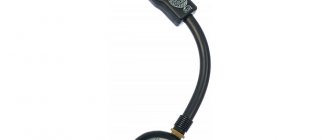
- The fuel hose is about a meter long.
- Fuel system "Y" connector.
All that remains is to assemble the structure.
Stages
If all the necessary parts have been collected, the assembly consists of the following sequence of actions:
- At the first stage, the gas cord is cut into three parts.
- Next, the gasoline hose must be connected to the fuel system connector. The reliability of the connection is ensured by clamps. The connections must be well sealed and not allow air to pass through, otherwise the readings obtained during measurements will be incorrect.
- We attach a pressure gauge to one end of the fuel cord. It also needs to be securely secured using a fitting and a clamp. You need to remove the pressure gauge from the fitting; it is not needed for measurements.
A homemade device can be used to monitor and regulate pressure in the fuel system.
Read with this