Legislative framework of the Russian Federation
Free legal aid hotline
Navigation
Federal legislation
Actions
- home
- “RULES FOR THE CONSTRUCTION AND SAFE OPERATION OF PRESSURE VESSELS. PB 10-115-96" (approved by Resolution of the State Mining and Technical Supervision of the Russian Federation dated 04/18/95 N 20) (as amended on 09/02/97)
| Name of document | “RULES FOR THE CONSTRUCTION AND SAFE OPERATION OF PRESSURE VESSELS. PB 10-115-96" (approved by Resolution of the State Mining and Technical Supervision of the Russian Federation dated 04/18/95 N 20) (as amended on 09/02/97) |
| Document type | resolution, list, rules |
| Receiving authority | Gosgortekhnadzor of the Russian Federation |
| Document Number | 20 |
| Acceptance date | 01.01.1970 |
| Revision date | 02.09.1997 |
| Date of registration with the Ministry of Justice | 01.01.1970 |
| Status | cancelled/lost force |
| Publication |
|
| Navigator | Notes |
5.3.1. Each vessel and independent cavities with different pressures must be equipped with direct-acting pressure gauges. The pressure gauge is installed on the vessel fitting or pipeline between the vessel and the shut-off valve.
5.3.2. Pressure gauges must have an accuracy class of at least: 2.5 - at a vessel operating pressure of up to 2.5 MPa (25 kgf/sq. cm), 1.5 - at a vessel operating pressure above 2.5 MPa (25 kgf/sq. cm ).
5.3.3. The pressure gauge must be selected with a scale such that the limit for measuring working pressure is in the second third of the scale.
5.3.4. The owner of the vessel must mark the pressure gauge scale with a red line indicating the operating pressure in the vessel. Instead of the red line, it is allowed to attach a metal plate painted red to the pressure gauge body and tightly adjacent to the glass of the pressure gauge.
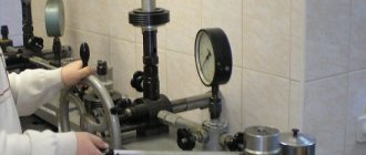
5.3.5. The pressure gauge must be installed so that its readings are clearly visible to operating personnel.
5.3.6. The nominal diameter of the body of pressure gauges installed at a height of up to 2 m from the level of the observation platform must be at least 100 mm, at a height of 2 to 3 m - at least 160 mm.
Installation of pressure gauges at a height of more than 3 m from the site level is not permitted.
5.3.7. A three-way valve or a device replacing it must be installed between the pressure gauge and the vessel, allowing periodic checking of the pressure gauge using a control valve.
In necessary cases, the pressure gauge, depending on the operating conditions and the properties of the medium in the vessel, must be equipped with either a siphon tube, or an oil buffer, or other devices that protect it from direct exposure to the medium and temperature and ensure its reliable operation.
5.3.8. On vessels operating under pressure above 2.5 MPa (25 kgf/sq. cm) or at ambient temperatures above 250 degrees. C, as well as with an explosive atmosphere or harmful substances of hazard classes 1 and 2 according to GOST 12.1.007, instead of a three-way valve, it is allowed to install a separate fitting with a shut-off device for connecting a second pressure gauge.
On stationary vessels, if it is possible to check the pressure gauge within the time limits established by these Rules by removing it from the vessel, the installation of a three-way valve or a device replacing it is not necessary.
On mobile vessels, the need to install a three-way valve is determined by the vessel design developer.
5.3.9. Pressure gauges and pipelines connecting them to the vessel must be protected from freezing.
5.3.10. The pressure gauge is not allowed for use in cases where:
there is no seal or stamp indicating verification;
when it is turned off, the arrow does not return to the zero scale reading by an amount exceeding half the permissible error for this device;
the glass is broken or there is damage that may affect the accuracy of its readings.
5.3.11. Checking of pressure gauges with their sealing or branding must be carried out at least once every 12 months. In addition, at least once every 6 months, the owner of the vessel must carry out an additional check of the working pressure gauges with a control pressure gauge and record the results in the control check log. In the absence of a control pressure gauge, it is allowed to carry out an additional check with a proven working pressure gauge that has the same scale and accuracy class as the pressure gauge being tested.
The procedure and timing for checking the serviceability of pressure gauges by maintenance personnel during the operation of vessels should be determined by the Instructions for the operation mode and safe maintenance of vessels, approved by the management of the organization that owns the vessel.
Division by functional purpose
According to their intended purpose, the following types of pressure gauges used to measure gas pressure are distinguished:
Let's look at the features of each type.
Pressure gauges for general technical purposes
This type of pressure gauges is produced for the purpose of measuring vacuum and excess pressure values for general technical purposes. Various modifications of the devices allow them to be used in a wide variety of environments. They are used to measure pressure in production directly during technological processes.
Such pressure gauges can measure the pressure of gaseous media that are non-aggressive towards copper alloys at operating temperatures up to 150 °C. Typically, the body of the product is made of steel, and the mechanism parts are made of brass alloy.
General technical pressure gauges for low or high pressure gas are manufactured to be resistant to vibrations with a frequency in the range from 10 to 55 Hz, as well as a displacement amplitude of a maximum of 0.15 millimeters. They have several accuracy classes from 1 to 2.5.
Gas pressure gauges for general technical purposes with an electronic board on which the measurement data are displayed are gaining popularity. They are often equipped with converters, which automates technological processes. Pressure values are displayed on an electronic dial.
Group of special pressure gauges
Such devices are manufactured for a specific type of gas and the environment it creates. For systems with increased pressure, pressure gauges are made for high-pressure gas. Some gases are aggressive towards certain alloys, so it is necessary to use resistant materials when working with them.
Special pressure gauges are painted in different colors depending on the type of gas.
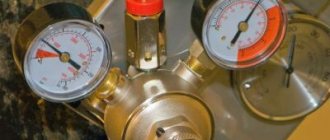
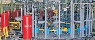
Propane pressure gauges are painted red, have a steel body and have the characteristics of general technical pressure gauges. The operating pressure of such devices is from 0 to 0.6 MPa. This is standard propane pressure. Operation is possible in the temperature range from – 50 to + 60 °C. Working environment temperature up to + 150 °C. Often included with balloon reducers.
Ammonia pressure meters in cylinders and other containers are colored yellow. Units with multi-stage compression are equipped with a temperature scale. The pressure gauge components are made of materials resistant to ammonia vapors.
The acetylene pressure gauge is painted white. Manufactured as a pressure gauge for security systems from fat-free materials. Used to measure excess pressure in various acetylene distribution and generating systems. The body is made of steel, the internal components are made of brass alloy. The permissible temperature range is from – 40 to + 70 °C.
The hydrogen pressure gauge turns dark green. The pressure gauge for other flammable gases is painted red. The measuring device for non-flammable mixtures is painted black. The oxygen pressure gauge is painted blue.
Reference devices for pressure measurement
This type of pressure gauge is designed to test, calibrate and adjust other instruments to ensure the highest possible measurement accuracy. Such devices are distinguished by a higher accuracy class in comparison with general technical ones. Working standards are divided into three categories.
Control pressure gauges, used to monitor the reliability of the readings of measuring instruments at the installation site, are also called high-precision pressure gauges. The operating measurement range is from 0-0.6 to 0-1600 bar for gaseous media.
Pressure gauges for conventional and composite gas cylinders must undergo a verification procedure at least once a year, unless other periods are specified in the documents for the device. Verification is carried out by accredited metrological organizations that have the status of legal entities. After verification, a certificate is issued and a stamp is placed.
The transmission mechanisms in the reference pressure gauges are machined at a higher gearing frequency. They are characterized by minimal friction in the pointer mechanism, as well as high sensitivity of the internal elements.
Standard pressure gauges with an accuracy class of 0.4 have a scale of 250 units, with an accuracy class of 0.15 or 0.25 they have a scale of 400 units with a division value of 1 unit. Operation of the device is possible at different temperatures depending on the housing filler. The ideal operating temperature is 20 °C.
The following article will introduce you to the specifics of refilling gas cylinders. All owners of country property not connected to a centralized gas supply should read it.
Frequency of checking pressure gauges
A pressure gauge is a device that measures pressure in a device, container, or pipeline. There are several types:
- spiral;
- membrane
Spiral pressure gauges consist of a metal spiral that is connected by a transmitting element connected to a pointer on a dial. The higher the pressure, the more the spiral unwinds and pulls the arrow along with it. Which is reflected in an increase in pressure readings on the instrument scale.
The diaphragm pressure gauge provides readings due to a clamped flat plate, which is connected to the transmitting element. When exposed to pressure, the membrane bends and the transmitting element presses on the dial arrow. This is how blood pressure increases.
To check the compliance of the accuracy parameters of the meter declared by the manufacturer and to monitor the metrological serviceability of the device, without which the pressure gauge cannot be used in areas falling under GROEI (state regulation for ensuring the uniformity of measurements), and also to ensure that the device serves the established period and operation is safe, it should be periodically carried out checking the pressure gauge. The rules set by the state state that, depending on the technical characteristics of the device and the manufacturer's instructions, the reconciliation period ranges from 12 months to 5 years.
Regular inspection of the device after a year was considered the most common, but now manufacturers are improving the characteristics of the equipment, and devices with a verification period of 2 years are increasingly found. It is worth remembering that the pressure gauge must undergo inspection and verification after a certain period from the date of production, and not from the moment it is put into operation.
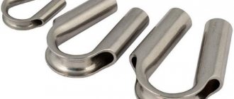
Siphon tubes
There should be a three-way valve or similar device in front of the pressure gauge to purge and shut off the pressure gauge. To increase service life, the pressure gauge spring should not interact with steam, but only with water. In front of the pressure gauge installed on the steam line, there must be a siphon (loop) tube with a diameter of at least 10 mm, which protects the device from pressure pulsations and high temperatures. It can be of different lengths, but it must have bends, which are made for two reasons: they remove the pressure gauge from the medium, which has a high temperature, and facilitate better filling of it with condensate. A three-way valve is installed between the pressure gauge and the siphon tube. It is used to purge the tube and check the pressure gauge by setting it to zero.
Instructions for making the device yourself
In order not to spend money on buying a ready-made fuel pressure gauge, you can make it yourself. It is necessary to assemble all the components correctly so that the measurements are accurate.
This is important for diagnosing the fuel system
Tools and materials
In order to make a fuel meter, you need to prepare the following components:
- It is better to take a VAZ pressure gauge with the ability to measure oil pressure. To do this, unscrew the gasoline fitting and insert the hose instead of the oil pressure regulator. If the threaded connection does not fit, you will have to purchase an adapter.
- Adapter - fitting with 7/16-20 UNF thread.
- We purchase a gas filter for its fittings. Therefore, you can buy the cheapest gas filter or find a used one, cut off its fittings, slightly flaring the ends. If possible, you can grind the fitting yourself.
- Clamps – 4 pcs.
- The fuel hose is about a meter long.
- Fuel system "Y" connector.
All that remains is to assemble the structure.
Stages
If all the necessary parts have been collected, the assembly consists of the following sequence of actions:
- At the first stage, the gas cord is cut into three parts.
- Next, the gasoline hose must be connected to the fuel system connector. The reliability of the connection is ensured by clamps. The connections must be well sealed and not allow air to pass through, otherwise the readings obtained during measurements will be incorrect.
- We attach a pressure gauge to one end of the fuel cord. It also needs to be securely secured using a fitting and a clamp. You need to remove the pressure gauge from the fitting; it is not needed for measurements.
A homemade device can be used to monitor and regulate pressure in the fuel system.
Read with this
Pressure drop
When water flows through a pipe, the pressure at the outlet will be less than at the inlet.
The fall is determined by several factors:
- Pipe diameter.
- Its length.
- The roughness of her walls.
Plastic water pipes have much smoother walls than any metal ones.
- The speed of the flow in it.
The formula used for calculation is H = iL(1+K).
- H – pressure drop in meters. To convert it to atmospheres, it is enough to divide the resulting value by 10.
- i is the hydraulic slope, determined by the diameter, material of the pipe and the flow rate in it.
- L is the length of the pipe in meters.
- K – coefficient, for domestic and drinking water supply systems, taken equal to 0.3.
Where can I get the hydraulic slope value? In the so-called Shevelev tables. Here is a fragment of one of them, relevant for a new steel pipe of size DN15.
| Water consumption, l/s | Flow speed, m/s | 1000i |
| 0,17 | 1,00 | 266,2 |
| 0,18 | 1,06 | 296,1 |
| 0,19 | 1,12 | 327,6 |
| 0,20 | 1,18 | 360,5 |
| 0,25 | 1,47 | 560,4 |
| 0,30 | 1,77 | 807,0 |
| 0,35 | 2,06 | 1098 |
The value 1000i is the hydraulic slope for a pipe length of 1 km. To calculate the value of i for a linear meter, it is enough to divide it by 1000.
So, for a DN15 steel pipe 25 meters long with a water flow through it of 0.2 l/s, the pressure drop will be (360.5/1000)*25*(1+0.3)=11.7 meters, which corresponds to the difference pressure of 1.17 kgf/cm2.
The hydraulic slope values given are valid for new pipes. Over time, lime and rust will increase their hydraulic resistance and reduce clearance.
Instruments for measuring pressure. What are the requirements for pressure gauges?
The accuracy class of pressure gauges must be no lower than:
2.5 - at operating pressure up to 2.5 MPa (25 kgf/cm 2);
1.5 - at a working pressure of more than 2.5 MPa (25 kgf/cm 2 ) up to 14 MPa (140 kgf/cm 2 );
1.0 - at a working pressure of more than 14 MPa (140 kgf/cm 2 ).
The pressure gauge scale is selected so that at operating pressure the pressure gauge needle is in the middle third of the scale.
The pressure gauge scale should have a red line indicating the permissible pressure.
Instead of the red line, it is allowed to attach to the pressure gauge body a metal plate painted red and tightly adjacent to the pressure gauge glass.
The pressure gauge must be installed so that its readings are clearly visible to operating personnel, and its scale should be positioned vertically or tilted forward up to 30° to improve the visibility of the readings.
The nominal diameter of pressure gauges installed at a height of up to 2 m from the level of the pressure gauge observation platform must be at least 100 mm, at a height from 2 to 3 m - at least 150 mm and at a height from 3 to 5 m - at least 250 mm. When the pressure gauge is located at a height of more than 5 m, a reduced pressure gauge must be installed as a backup.
In front of each pressure gauge there should be a three-way valve or other similar device for purging, checking and disconnecting the pressure gauge. In front of a pressure gauge designed to measure steam pressure, there must be a siphon tube with a diameter of at least 10 mm.
What are the methods of non-destructive testing of pipeline welds?
The main methods of non-destructive testing of materials and welded joints are:
visual and measuring;
capillary or magnetic particle;
In addition, other methods (acoustic emission, etc.) can be used.
Source
Installation and removal rules
To ensure stable operation of the pressure gauge and reduce the risk of its breakdown, follow certain rules:
- The installation of pressure gauges must be carried out in such a way that it would be quite easy to take measurement results and carry out routine maintenance and repairs.
- The rules define a number of conditions that determine the maximum dimensions of the distances between the measuring device and the walls of the room in which the device is installed.
- If the pressure gauge is mounted at a height of 2 to 3 meters, the diameter of the housing must be no less than 160 mm. It is unacceptable to install pressure gauges at a height of more than three meters. This is defined in the requirements of regulatory documentation.
- To carry out the checks of measuring instruments and equipment prescribed in the regulatory documentation when using the instruments, a three-way valve must be installed in the installation structure. Its installation location should be between the pressure gauge and the pipe (vessel).
- When installed in conditions where it may be influenced by external external factors, for example, precipitation or high temperature, it is necessary to provide additional protection. For this purpose, so-called buffer elements, siphons and other products are used. The efficiency of the installed measuring equipment depends on how well it is protected from external influences.
- To prevent freezing of the measuring instrument, they are provided with thermal insulation.
- When connecting, it is necessary to vent any gas that has entered the system. To do this, slightly tighten the fixing nut on the fitting.
- Pressure gauges that have not been verified and do not have a seal or appropriate seal on the body should not be allowed to be used for operation in networks. If the verification period has expired, or during operation it turns out that the operation differs from the standard one, then it must be removed and sent for diagnostics and repair. If damage appears on the meter body, or a crack appears on the glass, then such a device cannot be used and must be disposed of.
- Damaged sensors are dismantled and transferred to a certified laboratory for repair work. If such a pressure gauge cannot be restored, then it is disposed of.
Water pressure in the water supply
Low pressure level
With a fairly low pressure, which is manifested by a fairly weak water supply directly from the tap and indicates a completely low level. A fairly pressing and common problem is for residents of upper floors, as well as owners of country houses. Low pressure in the water supply will prevent many necessary household appliances from working, which will become a significant problem, and there will also be a desire to correct this situation.
Carrying out installation work to install equipment that can increase this indicator is a fundamental technique for ensuring a solution to this issue. Naturally, before using modern units designed for these purposes, it is necessary to determine whether the system is clogged, which may also be one of the reasons for this phenomenon.
In a certain way, this problem can be completely eliminated with the help of a specialized pumping unit, which will help increase the pressure, or by modernizing the system itself by integrating the pumping station with the storage tank.
Naturally, a more rational and suitable method should be determined directly by the owner himself, which is determined by the goals being pursued, as well as the necessary volumes of liquid that will be required to fully provide the home.
Where to measure pressure
Considering the factors influencing the decrease in water pressure in the water supply system, it is important to understand that the water pressure at the entrance to the apartment may differ from the water pressure at the water intakes. Most likely this change will be minor, but it will happen.
Therefore, in order to dispute with the management company, you need to measure the water pressure at the water supply inlet to the apartment. To study the connection conditions for a new household or plumbing appliance, you need to measure the water pressure at the connection point of this device.
For example, you want to buy a washing machine that can only operate at a water pressure of 1.6 bar. Ideally, water pressure should be measured at the washing machine connection point, and not at the water supply inlet.
How to use a technical pressure gauge
Maintenance of a technical pressure gauge consists of several simple operations. In particular, this is checking its performance, reading information from the measuring scale, applying pressure, and performing zeroing. If the liquid in the device is contaminated, it must be changed, otherwise it will lead to distortion of the measurements taken. When carrying out maintenance, it is necessary to check that there is a sufficient amount of working fluid. If its level is insufficient, it must be topped up, guided by the requirements of the operating instructions for the measuring device.
Most inclined instruments have a built-in device for leveling the pressure gauge. The device can be rotated until the bubble in the level takes the correct position at the zero mark.
Installation method on a three-way valve
If it is planned that when checking data it will be necessary to switch the device to atmospheric pressure, then, as a rule, a three-way valve is installed in front of it. It is used to supply atmospheric air. In addition, the installation of pressure gauges with a three-way valve and a siphon tube allows the device to be replaced without interrupting the supply of the working medium. In addition, the presence of such a crane allows you to perform various works when stopping its work is not necessary.
Operation and installation
Correct operation guarantees trouble-free operation and correct readings, therefore the following conditions must be observed:
- The device must be used to measure pressure only in the environment for which it is intended;
- Load the device with pressure gradually and avoid sudden pressure surges;
- do not exceed the measurement range;
- Do not use solvents or abrasives to clean glass.
The device should be taken out of service and sent for repair if:
- the device does not work;
- the arrow moves irregularly or does not return to the zero mark;
- the reading error exceeds the permissible value.
In the absence of pressure, the arrow should be within the zero mark area. Deviation of the arrow beyond this area indicates a malfunction of the device.
Installation (dismantling) of devices is carried out in the absence of pressure in the pipeline. The instrument must be installed either in the normal operating position (instrument position with the dial vertical (permissible deviation ±5° in any direction)) or in accordance with the operating position symbol indicated on the dial. During installation, the device may only be rotated by the fitting using a wrench. It is prohibited to apply force to the device body. The installation torque should not exceed 20 N∙m. Pressure supply is carried out through pipelines with an internal diameter of at least 3 mm.
When measuring the pressure of a medium with a temperature exceeding the permissible operating temperature, it is necessary to install a siphon loop tube or radiator in front of the device. Also, a radiator or siphon loop tube can be installed to reduce the influence of medium temperature on the accuracy of pressure gauge readings.
A typical selection unit for connecting a pressure gauge consists of a welded boss with a platform for a sealing gasket (BP-TM-30-G1/2 or BP-TM-30-M20x1.5), a siphon loop tube, and a three-way valve. It is recommended to use a paronite, fluoroplastic or copper gasket as a seal in threaded connections between the welded boss, tap and pressure gauge.
Existing methods of connecting a pressure gauge
The first and most important point is that the installation of a pressure gauge can only be carried out when there is no pressure in the system. It is also worth paying attention to the following points for connecting the pressure gauge:
- The pressure gauge scale should be positioned vertically.
- Strict adherence to installation tolerances is required.
- The rules for installing pressure gauges require the use of a wrench.
- It is important not to apply any load to the housing when connecting the pressure gauge.
At the moment, there are 3 types of connecting pressure gauges - direct, using a three-way valve and using a selection device. Let's look at each of them in more detail.
Installation features
Installation of a pressure gauge is only possible in a site where the pressure has been relieved. The device is installed in its working position. It is usually specified in the instructions. It also specifies installation tolerances. The pressure gauge is installed using a wrench. In order not to overload the device body, it is necessary to ensure that the tightening torque does not exceed 20 N*m.
You can install a pressure gauge to measure water pressure in a water supply in the following ways:
- Straight. The device is mounted in the places noted in the design documents, for example, before and after the valves. The adapter is placed at the installation point. It is connected to the pipeline by welding or screwing. The pressure gauge is installed in a direct way in cases where the system operates stably, without pressure surges.
- Using a three-way valve. If the measurement data needs to be checked for atmospheric pressure, a three-way valve is installed for this purpose. Atmospheric air is supplied through it. Replacing a pressure gauge installed in this way does not require interruption of the medium supply.
- Using an impulse tube. It protects the pressure gauge mechanism from pressure changes. To install the device, you must use an adapter. Then a tube, a three-way valve and the sensor itself are placed on the pipeline. This method is used in cases where the working environment has an operating temperature exceeding standard values.
To ensure stable operation of the pressure gauge and reduce the risk of malfunctions, certain installation requirements must be observed:
- Installation is carried out in such a way that it is easy to take measured indicators, carry out maintenance and repairs.
- If the pressure gauge is placed at a height of 2-3 m, the diameter of the housing must be greater than 160 mm. Installation of the device at a height exceeding 3 m is prohibited.
- A quick check of the pressure sensor can be ensured by installing a three-way valve in the structure, which should be located between the pipe and the pressure gauge.
- When installing equipment under conditions of possible exposure to external adverse factors (high temperature, precipitation), it is necessary to create additional protection for the device. For this task, siphons and buffer elements are chosen.
- Thermal insulation prevents the sensor from freezing.
- When connecting a pressure gauge to measure pressure, you need to bleed off the gas that has entered the system. To do this, the fixing nut on the fitting is not tightened a little.
After installing the device and putting the system into operation, you should not immediately load it. It is better to increase the pressure gradually, avoiding sudden pressure surges. Such measures can extend the service life of the sensor.
When installing a pressure gauge to measure pressure, check the tightness of the connection between the measuring device and the fitting. For this purpose, FUM tape or thread is usually used. To make the joint more reliable, use a sealant. All products must comply with operating conditions. For example, for superheated steam with a temperature above 130 degrees, it is unacceptable to use FUM tape, which is designed for a maximum heating of 95 degrees. Some installation companies use tow as an insulator, which should not be allowed.
Source
Direct installation method
They are installed in those places indicated in the design documentation, for example, before and after valves. An adapter must be installed in the place where the pressure gauge is installed. It is either welded, sometimes they are screwed in. Welding is the most affordable way to fix adapters.
The direct method is used for installing devices that operate in a stable environment without any pressure surges and frequent replacement of the measuring sensor.
Read also: Is it possible to connect an Internet cable by twisting it?
Methodology for checking pressure gauges
There are quite a large number of different technologies that allow you to determine the condition of a measuring device. Checking of technical pressure gauges should be carried out exclusively by professionals, since mistakes made can cause a decrease in the accuracy of the readings. Services should only be provided by specialists who have received appropriate permission.
There are several most common verification technologies:
When using a hydraulic press. In this case, the measuring device is installed between two elements of the device. It is worth considering that this measurement technology is characterized by low error. There are quite a large number of different types of hydraulic presses, all of them are characterized by their own specific features. This design is found exclusively in specialized stores; to use it you must have certain skills and knowledge. When using a metrological stand. In this case, the main indicators are taken with a minimum error at the established control points. Such a device creates the required pressure in the system. Among the features of using a metrological stand, we note that the measurement errors are quite high. However, the design features make it possible to significantly expand the scope of application of the device, for example, in the case of high pressure in the system. When using a special calibrator. This device can be purchased today in a specialized store for self-verification of the device
When choosing a calibrator, attention is paid to the range of indicators it can be used in. Most of the models work according to the same scheme.
The device is characterized by high mobility and can be used without special training.
How to fill a closed heating system
At the lowest point of the system, usually on the return pipeline, an additional tap is installed to feed/drain the system. In the simplest case, this is a tee installed in a pipeline, to which a ball valve is connected through a small section of the pipe.
The simplest unit for draining or filling coolant into the system
In this case, when draining the system, you will need to substitute some kind of container or connect a hose. When filling the coolant, a hand pump hose is connected to the ball valve. This simple device can be rented at plumbing stores.
There is a second option - when the coolant is just tap water. In this case, the water supply is connected either to a special boiler inlet (in wall-mounted gas boilers), or to a ball valve similarly installed on the return line. But in this case, another point is needed to drain the system. In a two-pipe system, this may be one of the last radiators in a line, with a drain ball valve installed at the lower free inlet. Another option is presented in the following diagram. Shown here is a closed-type single-pipe heating system.
Diagram of a closed one-pipe heating system with a system power supply unit
Rules for installing pressure sensors on pipelines
(Reference book “Measurement of parameters of gaseous and liquid media during the operation of engineering equipment of buildings” edited by A.A. Polyakov)
When installing pressure measuring instruments, it is necessary to protect the sensitive element of the device from factors that can lead to failure of the device, violation of its metrological characteristics (high temperature of the measured medium, extreme pressure pulsations, contact with the measured aggressive medium, etc.). Therefore, in pipelines with hot water and steam, discharge pipelines of pumps, etc., pressure measuring instruments are connected using connecting pipes equipped with a ring-shaped loop. Pressure pulsations, in addition, can be smoothed out by using damper vessels and chokes. After the ring-shaped loop, directly in front of the pressure gauge, a three-way shut-off valve is installed, designed to turn on and off the pressure gauge or sensor, check the zero point, purge the connecting line and carry out verification under operating conditions by connecting a reference pressure gauge.
Before connecting the pressure gauge to a pressure source with a high temperature of the controlled environment using a three-way valve, it is advisable to purge the connecting line. Purging ensures that the ring-shaped tube is well filled with the controlled medium. Measuring the pressure of a hot medium begins after the medium (or condensate) filling the connecting tube has cooled to ambient temperature. The testing of the sampling device is carried out together with the controlled object.
When measuring pressure from 10 to 40 MPa, at a medium temperature of more than 70˚C, a shut-off valve is installed in front of the annular tube in addition to the three-way valve.
Instead of a ring tube, a U-bend is often used on vertical pipelines.
Gas pressure is taken from horizontal pipelines at the top of the pipeline, liquid and steam pressure is taken from the side.
Sampling devices should not protrude into the controlled object.
When installing instruments for measuring the pressure of vapors and liquids, it is necessary to ensure that they are located at the same level as the pressure sampling point; if this is not possible, it is necessary to introduce a correction to the instrument readings. Liquid pressure gauges must be installed strictly vertically; pressure gauges of other types must also be installed in a vertical position if possible.
Source
Control questions
1. What is pressure?
2. What is the relationship between Pa and other units of pressure?
3. On what principle do pressure devices with elastic sensing elements work?
4. What types of elastic sensing elements are used in pressure instruments?
5. Why do you tap on the body of the calibrated and reference pressure gauges with elastic sensitive elements?
6. What explains the variation in readings of pressure gauges with elastic sensing elements?
7. What types of verification of pressure measuring instruments exist?
8. What should be the relationship between the class of the device being verified and the class of the reference device?
9. How to avoid the influence of the temperature of the measured medium when measuring pressure with a spring manometer?
Form 1
Protocol
verification of pressure devices of type _____, N _____, class ____, with measurement limits from ____ kgf/cm2 to ____ kgf/cm2. Scale division price ____. Verification was carried out using a standard device of type ____, N ____, class __, with measurement limits from ____ kgf/cm2 to ____ kgf/cm2.
Results of verification of readings, kgf/cm2
| Indications of the sample device | Indications of the device being verified | Absolute error | Arrow offset | Variation | Until-may-may sin-ness |
| straight stroke | reverse stroke | straight stroke | reverse stroke | straight stroke | reverse stroke |
| without knocking | with a tap-nod | without knocking | with a tap-nod |
Bourdon tube pressure gauges
Series G10 For general industrial applications and can be used on non-corrosive gases or liquids. In stock: 8723
PC.
Series G20-G21-G22 For industrial applications and can be used for aggressive gases or liquids.
Series G30-G32 For industrial applications and can be used for aggressive gases or liquids.
Series G70 With electrical contacts, with magnetic preload, designed for automation and control systems. When the pressure reaches the setting value, the circuit closes/opens.
Series G72 With electrical contacts, with magnetic preload, designed for automation and control systems. When the pressure reaches the setting value, the circuit closes/opens.
Series G74 With magnetic contacts designed for automation and control systems. When the pressure reaches the setting value, the circuit closes/opens.
Series G77 Pressure gauge with microswitches, explosion-proof
Test pressure gauges VNTA Pressure up to 315 bar
Classification of pressure gauges and operating principle
Depending on the operating characteristics of pressure measuring devices, they are classified into the following types:
- Piston. They include a cylinder containing a piston. During operation, the medium acts on one part of the pump, and the load presses on the other. The slider moves by moving the arrow. It shows a certain value on the instrument scale.
- Liquid. They contain a tube with liquid and a movable plug. When using such a device, the working medium presses on the plug, changing the level of liquid in the tube. The arrow of the device is set in motion.
- Deformation. Inside such products there is a membrane, which, when deformed, activates the pointer above the scale.
Modern pressure measuring devices are divided into mechanical and electronic. In the first case, the design of the device is as simple as possible. The electronic pressure gauge contains a contact assembly that can more accurately measure the pressure of the working medium. Such devices have found wide application in industry. They are used as exemplary models for testing pneumatic units and adjusting regulators in various automated systems. Many electronic pressure gauges store data on peak pressure values over a certain period of use.