Piston pump
Piston pump
(plunger pump) is one of the types of volumetric hydraulic machines in which the displacers are one or more pistons (plungers) performing reciprocating motion.
Rice. 2. Differential circuit for switching on a piston pump. During the movement of the piston to the left, part of the liquid is diverted into the rod cavity, the volume of which is less than the volume of the displaced liquid due to the fact that part of the volume of the rod cavity is occupied by the rod
Unlike many other positive displacement pumps, piston pumps are not reversible, that is, they cannot operate as hydraulic motors due to the valve distribution system.
Piston pumps should not be confused with rotary piston pumps, which include, for example, axial piston and radial piston pumps.
Fighting pulsation
One of the disadvantages of piston pumps, like other positive displacement pumps, is the pulsation of flow and pressure. Pulsations can be reduced by arranging several pistons in a row and connecting them to one shaft so that their operating cycles are shifted in phase relative to each other at equal angles. Another way to combat pulsation is to use a differential pump activation circuit (Fig. 2), in which liquid is pumped not only during the forward stroke of the piston, but also during the reverse stroke.
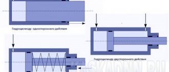
Double-acting pumps are also widely used, in which both the piston and rod chambers have (in contrast to the differential switching circuit) their own valve distribution system. Such pumps have a lower pulsation coefficient and higher efficiency than single-acting pumps (Fig. 1).
To combat pulsation, hydraulic accumulators are also used, which store energy at the moment of greatest pressure, and release it at the moment of pressure drop.
Piston pumps by type of action
1) single action
;
2) double action
.
Double-acting pumps have working chambers 1 and 2 on both sides of the cylinder, each of them has discharge valves 3 and 4 and suction valves 5 and 6. Therefore, both when the piston 10, driven by the rod 12, moves to the left and to the right in the cylinder 11, suction and discharge occur simultaneously. For example, when the piston moves to the right, in chamber 1 the suction valve 5 is open and liquid is sucked in, and in chamber 2 the discharge valve 4 is open, the liquid is supplied to the pressure pipeline. Thus, during one working stroke of the piston (movement to the right and left), almost double the volume of liquid is pumped in comparison with single-action pumps. Air caps 7 on the suction and 8 on the discharge, connected by tube 9, serve to reduce the pulsation of the pumped liquid;
3) built
pumps. They consist of three single-acting cylinders, the pistons of which are mounted on a common crankshaft, with the cranks located at an angle of 120° to each other. Thus, for every third revolution of the shaft, one portion of water is sucked in and released, thereby achieving more uniform operation;
4) twin
double acting pumps.
The pump consists of two double-acting pumps with common suction and discharge connections;
5) differential
pumps.
In a differential pump, the liquid is supplied more evenly, in two stages; During the stroke of piston 2 to the left, part of the liquid enters the right cavity of cylinder 1, and during the stroke of the piston to the right, it is supplied to the pipeline with only two valves 4 - suction and 5 - discharge, instead of four. In Fig. shown: 8 - suction air cap, 6 - discharge air cap, 7 - discharge pipe, 8 - rod. The dimensions of a differential pump are almost the same as a simple one. The rod 8 of the differential pump is made with a cross-sectional area equal to half the area of the piston; then equal volumes are supplied for each move.
Literature
- Hydraulics, hydraulic machines and hydraulic drives: Textbook for mechanical engineering universities / T. M. Bashta, S. S. Rudnev, B. B. Nekrasov and others - 2nd ed., revised. - M.: Mechanical Engineering, 1982.
- Geyer V. G., Dulin V. S., Zarya A. N. Hydraulics and hydraulic drive: Textbook for universities. — 3rd ed., revised. and additional - M.: Nedra, 1991.
Piston pump
called a reciprocating pump, the working parts of which are made in the form of pistons.
Based on the number of pistons,
these pumps are divided into
single-piston, double-piston, triple-piston and multi-piston
.
Based on the number of discharge and suction cycles in one double stroke of the piston,
single-acting, double-acting and differential
pumps are distinguished .
Diagram of a single-acting single-piston pump
presented on
rice. 3.1
.
When the piston moves to the right, a vacuum is created in the left cavity of the cylinder and in the working chamber. Due to the vacuum, the upper discharge valve Kn
is pressed against the seat, and the lower suction valve
K in
is raised, and liquid is sucked into the created gap through the suction pipe from the source into the working chamber.
When the piston moves to the left, increased pressure is created in the working chamber, under the influence of which the suction valve K in
closes, and the discharge valve
K n
is raised, and the liquid is forced out of the cylinder into the pressure pipeline.
With repeated reciprocating movement of the piston, water moves through the suction pipe through the pump cylinder into the discharge pipe and further to the point of consumption. In this case, the supply of liquid to the discharge line is uneven, which is a significant drawback
single-acting pumps. To eliminate this drawback, double-acting pumps are used.
With repeated reciprocating movement of the piston, water moves through the suction pipe through the pump cylinder into the discharge pipe and further to the point of consumption.
In Fig. 3.2
a diagram of a double-acting pump
is presented . The suction process in one chamber occurs simultaneously with the injection process in the other.
To ensure uniform flow, differential pumps (piston and plunger) are used. In Fig. 3.3
shows
a diagram of a differential pump
with piston diameters
D
1
and D
2
. On the suction side it operates as a single-acting pump, on the discharge side as a double-acting pump. Its distinctive feature is that during one revolution of the crank shaft it produces suction during one stroke of the piston, and injection of liquid during both strokes of the piston, displacing it alternately from chambers A
and
B
into the discharge pipeline.
In the direction of the axis of movement of the working bodies
piston (plunger) pumps can be
horizontal
or
vertical
.
Basic concepts used in pump theory
In Fig. Figure 3.4 shows a diagram of a pumping unit, consisting of a pump unit 1, which includes a pump and an engine (the engine is not shown in the diagram), a suction pipe 2 and a pressure pipeline 3, which discharges liquid from the pump to its destination.
There is a mesh at the bottom of the suction pipe 4
, which protects the suction pipe from foreign objects and a check valve necessary for filling the pump with liquid before starting (in vane pumps) and preventing the reverse movement of liquid if the pump stops.
Pump theory uses a number of terms and definitions that apply to pumps of all types, including piston pumps.
Pump head
In a working pump, additional energy is supplied to the liquid, which is spent on overcoming the resistance in the pressure pipeline and lifting the liquid into the reservoir. Vertical distance h
The entire distance
from the free surface of the reservoir to the center of the pump is called the vacuum suction lift
.
The energy loss in the suction pipe is called suction loss.
The vertical distance
h
n
from the center of the pump to the water level in the tank is called geodetic discharge height
.
The energy loss in a pressure line is called pumping loss
.
The sum of geodetic heights h
sun +
h
n
, added to the sum of energy losses in the system, is called pump pressure H
:
N
=
h
sun +
h
n +
h
w sun +
h
w n
. ( 7.9
)
Pressure
, developed by the pump,
is
the amount of energy imparted by the pump to a unit mass of the pumped liquid.
The head is measured
in meters of the column of pumped liquid or in units of pressure.
The pressure developed by a running pump can also be determined by the formula (7.9
) using the readings of a vacuum gauge and pressure gauge, which are usually equipped with pumping units (
Fig. 3.4
):
H
=
h
m +
h
in +
Δh
+ (
w
n 2 –
w
in 2) / (2
g
)
, ( 7.10
)
where N
– pump pressure,
m
;
h m
– pressure gauge reading, expressed in meters of the pumped liquid column;
h in
– vacuum gauge reading, expressed in meters of the pumped liquid column;
Δh
– vertical distance between the connection points of the pressure gauge and vacuum gauge,
m
;
w n
,
w
in
– velocities in the discharge and suction lines (at the points where the pressure gauge and vacuum gauge are connected), m/s
;
g
m/s 2
.
One of the main technical indicators of the pump is also the pump pressure
r
:
r
=
r
k –
r
n +
ρ
(
w
k 2 –
w
n 2) / (2
g
) +
ρ g
(
z
k –
z
n)
, ( 7.11
)
where p
k
, рн
– pressure at the outlet and inlet to the pump , Pa
;
ρ
– density of the liquid medium,
kg/m3
;
w to
,
w
n
– speed of the liquid medium at the outlet and inlet of the pump, m/s
;
g
– free fall acceleration,
m/s 2
;
z to
,
z
n
– height of the center of gravity of the cross-section of the outlet and inlet of the pump, m
.
Pump head N
and pump pressure
p
are related to each other by the relationship
N
=
р
/(
ρg
)
, ( 7.12
)
where ρ
– density of the liquid medium,
kg/m3
;
g
– free fall acceleration,
m/s 2
.
“The history of the invention of steam engines” - It is difficult to imagine our life without electricity. The first locomotive. The first steam car. Steam engines. Advantages. Definition. History of the invention of steam engines. Heron steam turbine. Target. Steam engine. A little history.
“Heat engines” - The working substance can be water vapor or gas. Engine "Younger brother" is a steam locomotive. Determine ways to increase efficiency. Finish. Efficiency of an ideal heat engine. A vital role. Average speed is 72 km/h. Homework. Carnot cycle. Environmental consequences of heat engines. I boarded a ship bound for London.
"The Invention of the Steam Engine" - Subsequent inventors made many improvements to the Newcomen pump. Such a double-acting engine was developed by Watt in 1782. Steam engine by Thomas Savery. The steam pressure supplied to the cylinder from the boiler (1) raised the piston. Factory production of steam engines began in 1776.
“History of the steam engine” - Steam engines with reciprocating motion. Steam engine. Russia's first two-cylinder vacuum steam engine. Vacuum machines. Creating a vacuum in a closed cylinder. How it works. Type of steam engines. What advantage do they have? The advantage of steam engines. Real steam turbine.
“Heat pumps” - The system operates stably, fluctuations in temperature and humidity in the room are minimal. Cross-section of various types of vertical ground heat exchangers. Construction of a soil probe. In winter, the heat pump system transfers the heat of the uncooled earth into the house. Housing construction projects (cottages, apartment buildings).
“Heat engine” - The first steam locomotive was designed in 1803 by the English inventor Richard Trevithick. Presentation for a 8th grade physics lesson “Heat Engines.” Machines that convert the internal energy of fuel into mechanical energy are called heat engines. Scottish engineer, mechanic and inventor, interested in steam and water condensation.
There are 11 presentations in total
This type of pump is one of the most ancient. Mechanical displacement of a liquid medium can be called the simplest implementation of the pumping principle. Nowadays, the designs of such units, of course, have a more complex structure compared to the first representatives of the class. In its modern form, a piston liquid pump has a durable housing, a developed element base and provides ample opportunities for communication. The latter aspect determines the distribution of equipment in various areas from domestic needs to highly specialized industrial sectors.
Analysis of the problem
To what height can water be raised with a conventional piston pump at normal atmospheric pressure?
It is important to understand that it is not we who drag the water up, but atmospheric pressure that pushes the liquid . By lifting the piston with our hands, we create an airless space, which causes the pressure outside the piston to increase and push out the liquid.
And just as a person cannot lift a truck with his hands, atmospheric pressure is not infinite and will raise a column of liquid of a certain height.
The liquid will rise as long as its pressure is less than atmospheric. That is, when the pressure of the liquid column is equal to atmospheric pressure, the height of the column will be greatest.
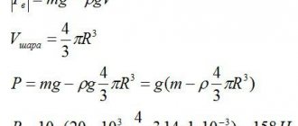
$$p=\rho gh$$
- $p$ – pressure of the liquid column and the value of normal atmospheric pressure (760 mm Hg or 101,300 Pa)
- $\rho$ – water density ($997 \frac{kg}{m^3}$)
- $g$ is the acceleration of free fall.
Let's express the height $h$ from this formula:
$h=\frac{p}{\rho g}=\frac{101300 Pa}{997\frac{kg}{m^3} \cdot 9.8 \frac{N}{kg}}≈10.4 m$
In the same way, we can calculate the maximum lifting height for other liquids if we know their density.
Pump device
The basis of the unit is a metal cylinder, in which working processes with liquid take place. Physical manipulation is performed by a piston containing valves. Experts also call such a system a plunger system, based on the type of piston mechanisms used. In essence, the main function in such systems is performed by a piston liquid pump, which operates on the principle of reciprocating motion, although it differs from classical hydraulic motors in the presence of a valve distribution system. The structure of the drive mechanism also includes a whole range of service parts and components. The parts of this design include the crank and connecting rod, which form the basis of the power working body.
The basis of the unit is a metal cylinder, in which working processes with liquid take place. Physical manipulation is performed by a piston containing valves.
Piston pumps according to the method of actuation:
1) drive, powered by a separately located engine connected to the pump by a crank mechanism or other transmission;
2) steam - direct acting; their pistons of pump 1 and 3 and steam cylinder 2 have a common rod 4
3) manual, manually actuated. These BKF type pumps are widely used.
Operating principle
In a simplified form, the function of such units resembles a conventional syringe or a water intake column, in which the carrier is replaced by a valve. But, there are also features that a piston liquid pump has. The principle of operation in this case provides that the receiving pipeline will also have a closing valve. Thanks to this device, liquid cannot flow back into the cylinder.
Despite the simple workflow scheme, such pumps have one significant drawback. The fact is that reciprocating actions do not imply a uniform and smooth supply of the media. The erratic rates at which a piston liquid pump operates can present challenges for downstream maintenance of receiving services. However, the use of several pistons allows us to minimize this disadvantage.
Despite the simple workflow scheme, such pumps have one significant drawback. The fact is that reciprocating actions do not imply a uniform and smooth supply of the media.
Principle of operation
From most of those who select technical devices for equipping pipeline systems, specialists hear: “Explain the operation of a piston pump with an air chamber.” It should be said right away that the principle by which the liquid piston pump, invented several centuries ago, operates is quite simple. It consists of the following: by making a translational movement, the piston creates a vacuum of air in the working chamber, due to which liquid is sucked into the chamber from the supply pipeline. With the reverse movement of the piston of such a pump, which, according to some historical data, was invented by an ancient Greek mechanic, the liquid from the working chamber is pushed into the discharge line. Piston pumps, as mentioned above, are equipped with a valve mechanism, the main task of which is to prevent the pumped liquid from getting back into the suction channel at the moment when it is pushed into the discharge line.
Working principle of single-ended piston pump
The principle by which piston pumps operate explains the fact that the flow created by such devices moves through the pipeline at different speeds, in jumps. To avoid this negative phenomenon, they use pumps equipped with several pistons operating in a certain sequence. The advantages achieved when using liquid pumps with multiple pistons also lie in the fact that such devices are capable of pumping liquid even when their working chamber is not filled with it. This quality of a multi-piston plunger pump, which is called “dry suction,” is relevant in many areas where such devices are used.
Piston pumps vary in number of actions
Double acting models
The appearance of this type of piston pump is due to the desire of manufacturers to eliminate the pulsation effect, which occurs precisely because of the rhythm in which the piston pushes out portions of liquid. In such pumps, the rod and piston cavities have individual valve systems. This principle of water supply distribution allows not only to eliminate pulsation, but also to increase productivity. True, one-way liquid piston pumps still have their advantages, which are expressed in a higher degree of reliability and durability. Another modification that was supposed to eliminate the rhythmic supply of fluid is a pump supplemented with a hydraulic accumulator. At the moment of peak pressure, such units collect energy, and when it decreases, on the contrary, they release it. However, it is not always possible to completely eliminate pulsation and operating companies have to appropriately develop liquid intake configurations outside the pump design.
How a piston water pump works and works
The design of a piston pump is simple. The water plunger pump consists of the following components:
- Frame.
It is not only a fastening element of the entire system, but also creates a vacuum and protects the device from various damages. Most models have a metal body; - Piston.
Creates the necessary pressure to supply water from the source to the pipeline system; - Inlet and exhaust valves
. They provide the supply of water and air to the system. Valves also help create a vacuum.
The design can be supplemented with springs, rods, cranks and other parts, depending on the design features.
The drawing of a piston pump is quite simple. The diagram shows the components of the unit.
Purpose of pumps
The appearance of this type of piston pump is due to the desire of manufacturers to eliminate the pulsation effect, which occurs precisely because of the rhythm in which the piston pushes out portions of liquid.
Such units are used in different areas. Its principle of operation does not involve working with large volumes of media, but it has many other useful qualities. Since during the displacement of each new “dose” the piston receives a new liquid under dry cylinder conditions, the use of the design is justified in the chemical industry. The specialized purpose of piston liquid pumps allows work with aggressive media, explosive mixtures and certain types of fuel. But the use of piston units is not limited to this. They are also used for domestic needs, for supplying clean water and irrigation. Again, such models are not designed for large circulation volumes, but are distinguished by their reliability and delicate handling of the liquid being served - in fact, this factor has led to the widespread use of pumps in the food industry.
According to the design of the working body:
1) piston engines themselves, in which a disk piston moves in a bored cylinder. O-rings or cuffs are used to seal the piston;
2) plunger (rock) ones, in which the working body is a plunger in the form of a hollow glass, which moves in the sealing gland without touching the inner walls of the cylinder. These pumps are easier to operate, since they do not have replaceable piston rings, cuffs, etc.; in Fig. a diagram of such a pump is given, where 1 is a rolling pin; 2 - cylinder; 3 - oil seal; 4 - discharge air cap; 5 - suction air chamber; V(k) and N(k) - suction and discharge valves;
3) diaphragm, in which the working body is a flexible diaphragm made of rubberized fabric or leather;
4) deep-sea pumps with a through-flow piston.
Advantages and disadvantages of the design
Among the advantages of such systems is the durability of the design. This is explained not only by the use of high-strength materials for the manufacture of components, but also by the operating principle itself. In addition, the piston liquid pump is distinguished by its ability to work with media that have high requirements for starting conditions. In particular, many experts note the benefits of “dry” suction, which not every pump can provide. As for the disadvantages, they mainly relate to low performance. Of course, it is theoretically possible to expand the technical parameters of the unit, but this will lead to increased operational requirements of the equipment. Moreover, many alternative designs can provide sufficient productivity at lower costs.