Types of hydraulic cylinders
Depending on the design, there are several types of hydraulic cylinders.
- By the nature of the move
- Single stage
- Telescopic
- In the direction of action of the working fluid
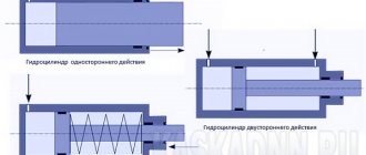
- Single acting
- Double acting
- If possible, braking
- With braking
- No braking
- By type of worker
- Plunger
- Membrane
- Bellows
- Piston With one-way rod
- With double-sided rod
Double-acting hydraulic cylinder design
Double-acting hydraulic cylinders have two separated sealed working cavities into which liquid is supplied through different pipelines. Double-acting hydraulic cylinders can transmit the developed force in both forward and reverse directions.
Let's consider the design of a double-acting hydraulic cylinder using the example of the most common design with a one-sided rod.
Hydraulic cylinder with one-way rod
The main structural elements of a double-sided hydraulic cylinder with a one-sided rod are shown in the figure.
- stock
- front cover
- sleeve
- piston
- screw
- back cover
- wiper
- rod cuff
- rod guide ring
- piston cuff
- rubber ring
- piston guide ring
Operating principle of hydraulic cylinder
The working fluid from the pump is directed through the distributor into one of the cavities (piston or rod), the opposite cavity is connected to the drain.
When fluid enters the piston cavity, the hydraulic cylinder rod extends, if necessary, overcoming the load force. When working fluid enters the rod cavity, the hydraulic cylinder rod is retracted.
| Extend the stem | Neutral position | Retract the rod |
When fluid enters the piston cavity, the force developed by the hydraulic cylinder can be calculated using the formula:
When liquid enters the rod cavity, the effective area will change; the rod area must be subtracted from the piston area.
The tightness of the working chambers is ensured by lip seals, which do not allow fluid to flow from the piston cavity to the rod cavity. A cuff is also installed in the hydraulic cylinder cover to seal the rod, and a wiper to prevent contamination particles from entering the cylinder cavity.
Hydraulic cylinder with double-sided rod
The force and speed of movement of the piston with the rod during forward and reverse stroke will be different. If the same forces are required or the same speed of movement of the output links, then hydraulic cylinders with a double-sided rod are used.
In this type of hydraulic cylinder, one piston is connected to two rods.
Hydraulic piston device
Hydraulics are structurally of two, characteristically different, types:
- The sliding inner plane of the liner, which has direct contact with the piston. This design requires the manufacture of a liner from antifriction materials;
- The piston, where sealing and guide rings slide along the liner, for which special grooves are machined. This is a more popular option that is cheaper to produce. The main material for the mechanism is steel.
To prevent the cylinders from leaking, cuffs and rings are used. If pressure is pumped from both the piston chamber and the rod side, install 2 in different directions. If pressure is applied only on one side, one cuff is sufficient.
Design of single-acting hydraulic cylinders
Single-acting hydraulic cylinders are capable of developing force in only one direction. The reverse stroke of such cylinders is carried out under the action of a spring, gravity, or external influence on the rod.
Plunger hydraulic cylinder
In hydraulic cylinders of this type, the liquid acts on a plunger located in the working chamber. The reverse stroke is carried out due to external forces or gravity.
The plunger is capable of transmitting only compression force; the magnitude of the force can be calculated using the relationship:
The speed of movement of the plunger will depend on the diameter of the plunger and the flow rate of the working fluid.
Spring return hydraulic cylinder
A spring return hydraulic cylinder is shown in the figure.
When the working fluid enters the piston cavity, a working stroke is carried out, the spring located in the rod cavity is compressed - the rod extends.
The reverse stroke is carried out due to the force of the spring, while the piston cavity is connected to the drain. The spring can be installed in both the piston and rod chambers.
Principle of operation
The piston is the main element of the hydraulic system. It moves back and forth inside the chamber and is driven by the working medium. The speed of movement depends on the intensity of the pressure of the process fluid. As a result of the process, it produces a transformation, a transfer of force. The energy of the piston is transmitted by a rod, which is attached to it through a pin. The stroke of the piston is limited by the size of the chamber. To soften contact, dampers are installed on the cylinder chamber covers.
The tightness of the system is ensured by seals - cuffs made of oil-resistant rubber.
Hydraulic cylinders of special design
Let's look at several special designs of hydraulic cylinders.
Telescopic hydraulic cylinders
In telescopic hydraulic cylinders, one rod is placed in the cavity of another rod. This makes it possible to obtain a large amount of movement of the output link with unchanged dimensions, since in telescopic cylinders the stroke can exceed the length of the sleeve.
Single-acting telescopic hydraulic cylinder
The working fluid is supplied to the cylinder cavity through the rear cover. The sections are pulled out sequentially - first, the section with the largest effective area will begin to move, then the one with the smaller one. The speed when extending each subsequent section will increase, and the force will decrease, due to a decrease in the effective area. For this reason, the force on the section with the minimum effective area should be calculated.
The reverse stroke is carried out under the influence of external forces, while the working cavity is connected to the drain.
Double-acting telescopic hydraulic cylinder
The supply of working fluid in the design shown in the figure is carried out through the rod.
The sections are extended in the same order as in single-acting telescopic hydraulic cylinders.
Characteristics of hydraulic cylinders
The main parameters of hydraulic cylinders can be divided into several groups.
Geometric parameters
- The diameter of the piston (liner), sometimes called the diameter of the hydraulic cylinder, the most common diameters are: 10, 12, 16, 20, 25, 32, 40, 50, 63, 80, 100, 125, 160, 200, 250, 320, 400 , 500, 620, 800 millimeters.
- Rod diameter, the following hydraulic cylinder rod diameters are standardized: 4, 5, 6, 8, 10, 12, 16, 20, 25, 32, 40, 50, 63, 80, 100, 125, 160, 200, 250, 320, 400, 500, 630, 800 millimeters.
- Stroke - the maximum possible movement of a piston with a rod or a hydraulic cylinder plunger
Hydraulic parameters
- Nominal operating pressure is the pressure at which the hydraulic cylinder will operate in the nominal, design mode, while maintaining the operating and reliability parameters guaranteed by the manufacturer. The pressure in the hydraulic cylinder is determined by the load value, and it can be limited by the settings of the safety or pressure relief valve. When there is no load, the pressure in the cylinder is caused only by friction losses.
- Fluid flow entering the hydraulic cylinder.
Mechanical parameters
- The force developed by a hydraulic cylinder is proportional to the pressure and effective area affected by the fluid.
- The speed of movement of the rod is determined by the amount of fluid flow entering the hydraulic cylinder and its effective diameter.
Hydraulic cylinder calculation
Let's try to understand how the characteristics of a hydraulic cylinder are related to each other, and how they are influenced by the operating parameters of the hydraulic drive.
When liquid enters the piston cavity, the liquid acts on the piston, the force developed by the hydraulic cylinder in this case will be proportional to the pressure and area of the piston:
The speed of movement of the piston with the rod will depend on the diameter of the piston and fluid flow:
When fluid is supplied to the rod cavity of the hydraulic cylinder, pressure will act on the annular surface formed by the outer diameters of the piston and rod. The force in this case can be calculated using the relationship:
Typical hydraulic cylinder designs
Despite the huge variety of designs of hydraulic cylinders, there are typical solutions used in the design of hydraulic cylinders; we will consider some of them.
Hydraulic cylinder on studs
The front and rear covers of hydraulic cylinders of this design are connected by pins (anchors), the sleeve is sandwiched between the cylinder covers. The piston is sealed by two cuffs.
Round hydraulic cylinder
In the presented design, the covers are attached to round flanges secured by welding or threading to the sleeve. The type of piston seal shown in the illustration provides sealing in both directions.
Welded hydraulic cylinder
The covers are welded to the sleeve, the structure is non-separable and cannot be repaired. The cylinder has compact piston seals.
Hydraulic cylinder drawing
Design documentation for a hydraulic cylinder must include:
- assembly drawing of a hydraulic cylinder,
- specification,
- working drawings of parts.
As an example of the design of a hydraulic cylinder, we suggest that you familiarize yourself with the assembly drawing of a single-rod double-acting hydraulic cylinder. The front cover of this cylinder has a threaded connection with the liner, the rear cover with an eye is welded to the liner. The piston is fixed to the rod using threaded bushings, secured against rotation using a pin.
To download a hydraulic cylinder drawing in pdf format, click on the image.
You can also download the hydraulic cylinder drawing in dwg format.
Source
How are hydraulic cylinders made?
Like other mechanisms, the hydraulic cylinder is subject to wear, which is associated with the overload to which all elements are subjected. As practice shows, it is more expedient to make a hydraulic cylinder yourself, or order it from a workshop, than to buy a new branded analogue. Savings can reach several thousand rubles. As a rule, a new hydraulic cylinder is produced to replace equipment that unexpectedly fails, or as a reserve, as a replacement for a hydraulic cylinder if signs of wear begin to appear, it should soon be written off.
The technology for creating a new custom hydraulic cylinder assumes that it is a one-off product. When creating it, the original is used, from which measurements are taken. The new unit must correspond in all technical characteristics to the failed one. To do this, before starting work, drawings and technical specifications are drawn up, and the old product is photographed. If possible, original factory documentation is obtained, which allows you to create an absolutely identical hydraulic cylinder.
Among the main points that should be specified in the technical specifications:
- Diameter of the stroke piston;
- Travel speed;
- Rod diameter;
- Operating pressure.
The technical documentation on the basis of which the new hydraulic system will be developed must be both concise and informative. The absence of errors, a responsible approach to the drawings is a guarantee that the customer will be given a piston that, in terms of its dimensions and, most importantly, technical characteristics, will fully correspond to the source.
Stages of creation
The production of a hydraulic cylinder requires modern equipment, high-quality materials, and knowledge of advanced technologies. Only by combining these elements can you create an original design that completely replicates the original features of the original mechanism.
The design of a hydraulic cylinder combines a sleeve, a rod, and seals. During the production process, these elements are machined and then assembled into a single system.
The manufacturing technology of a hydraulic piston consists of several stages:
- Pipes and rods are cut into blanks on a band cutting machine;
- The sleeve is chamfered from sections for welding work;
- The sleeve is welded into a single structure with rear covers and bonks;
- The rod is processed on a lathe and adjusted to the dimensions specified in the technical specifications;
- The elements are being assembled.
Before final assembly, all parts are washed in a washing machine. The seals are attached to certain areas of the hydraulic cylinder body using an installation tool. The heat resistance and tightness of the chamber where the cylinder runs is ensured by glue and o-rings.
Before transferring the finished order to the client, the hydraulics are tested on a test bench. The performance of the piston system is checked, both at idle and under various loads. The quality of the product is confirmed by the appropriate markings on the case, warranty card, certificate, product passport. The finished cylinder is packed in shipping packaging.
To ensure that the cylinder operates reliably throughout its entire service life, it is made from European components from trusted brands. The minimum period of the factory warranty is 12 months. The duration of the warranty depends on the type of cylinder, the materials from which it is made, and design features.
You can order the production of a hydraulic piston by calling the phone number and address indicated in the header of the site.