We offer rotation mechanisms in several modifications:
If you want to independently assemble a removable Lazy Susan spinning center with a diameter of 35 to 70 cm without attaching to the table surface, ML rotating mechanisms are suitable for you
If the removable rotating center is planned to have a larger diameter (from 80 to 140 cm), pay attention to the MX rotation mechanisms with additional support
If you plan to install a spinning center with a rigid mount to the table, use the MT spinning mechanisms. Rotating circle diameter from 40 to 140 cm
If the turntable is made of glass with a diameter of 35 to 70 cm, use MK rotation mechanisms
For a circle with a diameter greater than 140 cm, we will offer you another solution: a rotation mechanism with additional support rollers (Turn Kit)
Series ML. Rotating mechanisms for assembling a removable rotating table center
The ML rotating mechanisms are designed to assemble the Lazy Susan, a removable round rotating table center. The mechanism is a metal ball bearing consisting of two rings.
The outer ring has soft supports (dampers) for installation on the table, the inner ring has holes for attaching the mechanism to the rotating circle.
The mechanism is placed under the rotating circle, exactly along the axis of rotation of the circle. Layout of the rotating center on the table (side view):
The finished rotating center is not attached to the table surface in any way, but it stands stable and does not move. At any time, you can remove the spinning center from the table, move it to another table, or store it (but if you need a permanent spinning center that is rigidly fixed to the table, see MT mechanisms).
How to use ML rotating mechanisms - recommendations for assembling a removable rotating table center
ML mechanisms are suitable for attachment to circles made of chipboard, wood, MDF with a diameter of 35 to 70 cm. Load on the mechanism: up to 20 kg. Included: silicone dampers (6 pcs), 4x20 mm screws (6 pcs), felt stickers (12 pcs).
Prices for ML rotation mechanisms:
| 1950 | ~2 days. |
Complete the mechanism with a round tabletop of the diameter you need:
Read more about round tabletops
Round tabletops from our production
Need some advice? We will answer your questions:
Threaded connections
Threaded connections are the most common type of detachable connections, allowing for assembly or disassembly operations. The task of a threaded connection is to hold the connected parts in a given position with a force greater than the forces tending to separate these parts, preventing the joint from opening. Connection parts: bolt, nut, washer, stud. A bolt or stud is a force-elastic element in which a longitudinal force is created that tightens the flanges. The nut is the main fixing element. A washer is an element designed to reduce friction during tightening and uniformly distribute forces between the nut and the supporting surface of the flange.
Damage to threaded connections is associated with weakening of the tightening force, destruction of the load-bearing element and wear of the thread. Do not tighten threaded connections while the mechanism is running.
The performance of threaded connections is ensured by the integrity of the parts and uniform tightening of all elements with a given force.
MX series. Rotation mechanisms with additional support for large diameter wheels
The mechanism is fixed on a support platform (round or square):
The large support area allows you to install a round tabletop with a diameter of up to 140 cm on the mechanism.
The round tabletop (the future rotating circle) is attached to the ring mechanism with self-tapping screws. Before installing the tabletop, you must remove the mechanism from the support platform. Attach the mechanism to the tabletop. Then screw the platform back to the mechanism in its original place. All that remains is to place the assembled spinning center on the table and place the treats.
If necessary, the support platform is additionally attached to the table surface, for example, with self-tapping screws from below, through the table.
If you need advice on where to buy a round tabletop, write to us. Tabletops are offered by various suppliers in Russia; round tabletops are available in a variety of decors and colors.
The load on the MX mechanism is up to 50 kg.
Recommendations for mounting MX mechanisms when assembling a large diameter rotating table center
Prices for MX rotation mechanisms:
Mechanism | Price, rub | Production time | Order |
| MX-50. Mechanism with a round support made of 16mm chipboard with a diameter of 50cm. We recommend for installation of a rotating tabletop with a diameter of 70-80 cm. Height 2.8 cm. Product weight 3.5 kg. | Top view | Bottom view | 3600 | January |
Complete the mechanism with a round tabletop of the diameter you need:
Read more about round tabletops
Round tabletops from our production
For a circle with a diameter greater than 140 cm, there is another solution: the Turn Kit (rotation mechanism with additional support rollers)
Need some advice? We will answer your questions:
Torque transmission element
The element for transmitting torque from the drive element to the driven element is a key or splines (Figure 14).
| A) | b) | V) | G) |
Figure 14 – Types of key connections: a) parallel keys; b) segment keys; c) wedge keys; d) tangential keys
A key is a part installed in the grooves of two mating parts and ensuring their joint rotation. A keyed connection is a detachable connection that transmits torque and ensures the rotation of gears, pulleys and other parts, together with the shaft on which it is installed.
Key connections are divided into two groups: unstressed ones transmit moment by their side faces - prismatic (Figure 14a) and segment keys (Figure 14b), and tense ones - transmit moment due to friction forces along the upper and lower faces - wedge keys (Figure 14c) and tangential keys ( Figure 14d). Tangential keys - consist of two wedges with the same slope, arranged so that their working edges are mutually parallel.
Keyed connections must be repaired if a knock or play of the connected parts is heard during operation of the unit. Parallel keys must be replaced when the side faces and keyway are crushed; weakening the landing. In keyed connections, both the keys and the keyways wear out, resulting in a loose fit of the part on the shaft.
Spline joints are formed by projections on the shaft that fit into mating grooves in the wheel hub. Straight-sided splines are mainly used, less often involute and triangular profiles. The number of splines is assumed to be even. Straight-sided splines can center the wheel along the side surfaces, along the outer and inner surfaces (Figure 15).
Figure 15 – Types of centering of straight-sided spline joints: a) along the outer diameter; b) along the side surfaces; c) along the internal diameter
Wear of splines and cracks in connection parts are the most common faults. When the splines wear and collapse, the lateral clearances between them increase, as a result of which the impact force increases, and parts become distorted, causing overload of individual sections of the splines. Excessive wear and compression of the splines are accompanied by a characteristic knocking sound when the frequency and direction of rotation of the mechanism changes.
MT Series. Rotation mechanisms for a rotating table center with permanent (rigid) mounting
The MT mechanism is a metal ring ball bearing with mounting holes. The mechanism is attached between a rotating circle in the center of the table and the main tabletop. The MT mechanism has a permanent, rigid attachment to the table (but if you need a removable rotating center, see ML mechanisms)
The MT mechanism is universal: - You can fasten it with self-tapping screws; for this, the holes have recesses (countersinks) for the heads of the self-tapping screws. — Can be secured with M6 screws, all holes have appropriate threads. — Can be attached with double-sided tape.
Fastening with screws is much more reliable, but for the screws, through holes with countersinks must be pre-marked and drilled. The screw heads can be covered with decorative self-adhesive plugs. Or hide the screws by placing an overhead circle with imitation stone or tinted glass on top.
MT mechanisms are suitable for tables made of chipboard, wood, MDF - materials that you can drill or screw in screws.
Included : M6x25 mm screws (12 pcs). The length of the screws is 25 mm, selected for typical furniture parts with a thickness of 15-16 mm, with a deepening of the screw head - the holes are made with a countersink. If necessary, you can replace the screws with standard self-tapping screws with a diameter of 3.5 or 4 mm. The length of the screws may depend on the thickness of the furniture parts you use.
Recommendations for assembling the rotating table center:
Assembly with self-tapping screws on top + screws or tape on the bottom (without drilling a rotating circle)
Through mounting with screws on both sides
Recommended diameter of the turning circle for the MT-30 mechanism - When fastened with self-tapping screws: from 35 to 50 cm, load in the center of the circle up to 20 kg. — When fastened with screws: from 35 to 80 cm, load in the center of the circle up to 50 kg. — When fastened with double-sided tape: from 35 to 50 cm, load in the center of the circle up to 10 kg (load on the edge of the circle is undesirable).
Recommended diameter of the turning circle for the MT-40 mechanism - When fastened with self-tapping screws: from 55 to 80 cm, load in the center of the circle up to 20 kg. — When fastened with screws: from 55 to 140 cm, load in the center of the circle up to 80 kg. — When fastened with double-sided tape: from 50 to 60 cm, load in the center of the circle up to 10 kg (load on the edge of the circle is undesirable).
Prices for MT rotation mechanisms:
Mechanism | Price, rub | Production time | Order |
| MT-30 . Rotation mechanism, ring bearing with a diameter of 30 cm with threaded holes for fastening to furniture elements made of chipboard, wood, MDF | Mechanism kit | 1950 | ~2 days. |
Complete the mechanism with a round tabletop of the diameter you need:
Read more about round tabletops
Round tabletops from our production
For a circle with a diameter greater than 140 cm, there is a solution: the Turn Kit (rotation mechanism with additional support rollers)
Need some advice? We will answer your questions:
Gears
Gears are designed to change rotation speed and torque.
Cylindrical gears transmit torque between parallel shafts (Figure 10a, 10b, 10c). Spur wheels are used at low and medium speeds, when dynamic loads from manufacturing inaccuracies are small or when axial movement of the wheels is necessary. The main types of cylindrical gears: spur; helical; chevron; internal.
Helical wheels (Figure 10b) have a smoother ride and are used for critical mechanisms at medium and high speeds. The disadvantage of helical wheels is the presence of axial forces that affect the operation of bearings that compensate for these axial loads.
Chevron wheels (Figure 10c) have increased smooth operation, but do not cause axial forces, which are mutually balanced and are not transmitted to the bearings. Suitable for transmitting high powers with shocks occurring during operation.
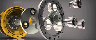
Internal gear wheels (Figure 10f) rotate in the same directions and are usually used in planetary gears.
In rotation transmissions between intersecting shafts, the gears have a conical shape. The work of the transmission can be compared to the rolling without slipping of two cones with their vertices at a common point (Figure 10d, 10e). Bevel gears can have straight, oblique and curved teeth, the latter providing greater smoothness of the transmission.
Figure 10 – Types of gears: a) cylindrical spur; b) cylindrical helical; c) chevron; d) conical spur; e) conical with a curved tooth; e) spur gear with internal gearing
Transmissions between crossing shafts are carried out by screw and hypoid wheels, a worm pair, and a globoid worm pair (Figure 11).
Screw wheels | Worm-gear |
Globoid transmission | |
Figure 11 – Transmissions between crossed shafts
Damage to gears
The main defects of gears are: chipping of metal on the working surface of the teeth; cracks of any nature and location; wear of teeth by thickness; wear of the bore and keyways.
The greatest wear of the working surfaces is observed on the legs of the teeth, where maximum sliding occurs. The fastest-growing type of damage, destruction, begins with the formation of a crack and ends with chipping or breaking of teeth. Cracks begin to appear at the base of the teeth on the side of the stretched fibers and are located perpendicular to the working surfaces of the teeth. The occurrence of cracks leads over time to the destruction of teeth and often to damage to other parts of the mechanism due to pieces of teeth getting into them.
Small clearances in gears lead to increased vibration and noise. In this case, the drive wheel tooth stem is cut and sharp edges appear on the tooth heads.
In worm gears, the threads of the worm wear out much more than the teeth of the worm wheel. In cylindrical gears, gear teeth wear more intensely than wheel teeth.
In open and closed gears, check the wear of the working surfaces, the presence of cracks, chips, breakages, irregularities in the correct engagement, gaps, end runouts, shaft displacements, and the presence of lubricant on the friction surfaces.
The performance of gears is ensured by: the absence of tooth defects and the geometric parameters of gears; correct relative position, regulated by the size of the contact patch; regulated value of lateral and radial clearance; fixed connection of parts.
MK series. Rotation mechanisms for glass round tabletops
The mechanism is a metal ring ball bearing with soft silicone dampers.
A simple method : a circle of glass is simply placed on top of the mechanism, and due to its weight it lies stably on the mechanism. Sticky silicone dampers prevent the wheel from moving out of place when rotating. Please note: the glass must be of sufficient thickness (and weight) to adhere securely to the dampers and to support the weight of objects placed on top.
A more reliable way : attach the circle to the MK mechanism with adhesive tape. To do this, it is better to use transparent double-sided acrylic foam tape with a thickness of 1 mm and a width of 8-9 mm. Such tapes are available for sale in various stores.
| Adhesive tape is applied to the inner ring of the mechanism | It is more convenient to attach the mechanism to the glass upside down. |
| The mechanism with adhesive tape is pressed against the glass exactly in the center | Now you can turn the assembled spinning center over and place it on the table |
When ordering, please let us know that you plan to secure the mechanism with adhesive tape.
Mechanism load: up to 20 kg.
Prices for MK rotation mechanisms:
Mechanism | Price, rub | Production time | Order |
| MK-30 . Rotation mechanism, ring bearing with a diameter of 30 cm with non-slip dampers. For stone or glass circle with a diameter of 35-45 cm | View from above | 1800 | ~2 days. |
Seals
Seals are devices that prevent or reduce the leakage of liquid or gas through the gaps between machine parts, as well as protecting the internal cavities of the mechanism from the penetration of dirt, dust, moisture, etc. There are two groups: fixed (Figure 12) and movable (Figure 13) sealing devices . Seals have small dimensions, but at the same time perform important functions. Damage to seals is associated with lubricant leaks and contaminants entering the mechanism.
| Gasket Installation | Installing the round rubber ring |
1 – installation nut; 2 – sealing ring; 3 – protective (fixing) washer | Conical filler plug |
Figure 12 – Seals of fixed joints
| Gland packing | Installing the cuff |
Sealing with rubber O-rings | Felt ring |
| Mechanical seal with bellows | Labyrinth seals with radial channels |
| Oil slinger ring | Throat seal with concentric grooves |
Figure 13 – Sealing of moving joints
Actuator element
An actuating element is an element that receives or releases energy: blades, a pump impeller, a conveyor drive or deflection drum, a roller conveyor, a lifting mechanism drum, etc. The actuating element is designed to carry out useful work in accordance with the functional purpose of the mechanism.
The operability of the mechanisms is ensured by compliance with the standards and requirements of the manufacturer, maintenance and repair in accordance with the requirements of the documentation of the operating organization.
Element for connecting shafts
Elements for connecting shafts - couplings: gear, elastic-bushing-pin, balloon, etc. (Figure 16). Couplings are designed to connect shafts. located on the same axis or at an angle to each other and transmitting torque. The coupling (with the exception of a rigid flange coupling) allows compensation for angular and radial displacement of shafts within the limits allowed by the design and dimensions.
Flange coupling: 1 – bolt; 2 – nut; 3 – washer; 4 – bolt; 5 – half coupling | |
Gear coupling | Spring coupling: 1, 5 – coupling halves; 2 – serpentine spring; 3 – screw; 4 – casing |
Bush-pin coupling: 1, 4 – half-coupling; 2 – finger; 3 – bushing | Balloon coupling: 1 – toroidal shell; 2 – half rings; 3 – rings; 4 – screws; 5 – half coupling; 6 – screws |
Figure 16 – Couplings
The performance of couplings is ensured by the integrity of the parts; alignment of mating shafts, uniform wear of elements within acceptable limits; immobility of the coupling halves relative to the shaft (for fixed couplings).
Questions for self-control
- What is a rotary mechanism, its purpose and design?
- Give a diagram of a two-support rotor mechanism.
- What are the main types of shafts and axles?
- Purpose, types and characteristic damage of bearings.
- What are gears used for and their types?
- Purpose of body parts and threaded connections.
- What functions do movable and stationary seals perform?
- Why are keys and splines needed in a mechanism?
- Main purpose and functions of couplings.
- What is the purpose of the actuator?
