If you have an old grinder among your tools, do not rush to get rid of it. Using a simple electrical circuit, the tool can be improved by adding the option of adjusting the rotation speed. Thanks to a conventional control device, which you can create with your own hands within a few hours, the functions of the tool will expand significantly. By reducing the number of rotations per unit of time, the angle grinder can be used as a sharpening and grinding unit for different types of materials. There will be additional opportunities for using auxiliary equipment and attachments.
How to make a speed controller for an angle grinder with your own hands?
If you have an old grinder , do not rush to get rid of it. Using a simple electrical circuit, the tool can be improved by adding the option of adjusting the rotation speed. Thanks to a conventional control device, which you can create with your own hands within a few hours, the functions of the tool will expand significantly. By reducing the number of rotations per unit of time, the angle grinder can be used as a sharpening and grinding unit for different types of materials. There will be additional opportunities for using auxiliary equipment and attachments.
Types of Voltage Regulators
Having understood what types of these devices there are, what their features and properties are, a complete understanding of the procedures carried out during testing will come. This will also give the answer to what scheme, in what way and how to check the generator voltage regulator. There are two types of regulators:
- combined;
- separate.
In the first case, it is meant that the regulator housing is combined with the brush assembly directly in the generator housing. In the second case, the regulator is a separate unit, which is located on the car body, in the engine compartment, and wires from the generator go to it, and wires from it go to the battery.
A special feature of the regulators is that their housings are non-separable. They are usually filled with sealant or special resin. And there is no particular point in repairing them, since the device is inexpensive. Therefore, the main problem in this regard is to check the generator voltage regulator relay. Regardless of the type of regulator, the voltage symptoms will be the same.
For what purpose does an angle grinder have low speeds?
The integrated option for adjusting the speed of the wheel makes it possible to carefully process materials such as wood or plastic. At lower speeds, comfort and safety increase. This option is most practical in radio and electrical installations, service stations and restoration studios.
In addition, among professionals who use power tools, there is a belief that the more trivial a device is, the more reliable it is. And it is advisable to take the additional service “filling” beyond the boundaries of the grinder. With this approach, equipment maintenance is greatly simplified. In this regard, some companies deliberately produce remote individual electric regulators that connect to the network cable of an angle grinder.
Why adjust the rotation speed of the grinder disc at all?
- When cutting metal of different thicknesses, the quality of work greatly depends on the speed of rotation of the disk. If you are cutting hard and thick material, you must maintain maximum rotation speed. When processing thin sheet metal or soft metal (for example, aluminum), high speeds will lead to melting of the edge or rapid blurring of the working surface of the disk;
- Cutting and sawing stone and tile at high speed can be dangerous. In addition, the disk, which rotates at high speeds, knocks small pieces out of the material, making the cutting surface chipped. Moreover, different speeds are selected for different types of stone. Some minerals are processed at high speeds;
- Grinding and polishing work is in principle impossible without adjusting the rotation speed. By setting the speed incorrectly, you can damage the surface, especially if it is a paint coating on a car or a material with a low melting point;
- The use of discs of different diameters automatically implies the presence of a regulator. Changing a disk Ø115 mm to Ø230 mm, the rotation speed must be reduced by almost half. And holding a grinder with a 230 mm disc rotating at a speed of 10,000 rpm is almost impossible to hold in your hands;
- Polishing of stone and concrete surfaces, depending on the type of crowns used, is carried out at different speeds. Moreover, when the rotation speed decreases, the torque should not decrease;
- When using diamond discs, it is necessary to reduce the number of revolutions, since their surface quickly fails due to overheating. Of course, if your grinder works only as a cutter for pipes, angles and profiles, you won’t need a speed controller. And with the universal and versatile use of angle grinders, it is vital.
Why does an angle grinder need a soft start and a speed controller?
Modern angle grinders use 2 necessary options that increase the performance and safety of the equipment:
- controller (frequency converter) – a device designed to convert the speed of the motor in different operating modes;
- soft start device - a circuit that ensures a leisurely increase in engine speed from zero to the maximum value when the unit is connected.
They are used in electromechanical equipment, the structure of which is an AC electric motor with a commutator. Helps reduce wear on the mechanical parts of the unit when turned on. They reduce the load on the electrical components of the machine, putting them into operation smoothly. As studies of the qualities of materials have revealed, especially strong production of contacting nodes occurs during the process of a sudden transition from a stationary state to rapid activity. For example, one start of an internal combustion engine in a car is equivalent to 700 kilometers of wear on the piston and a group of sealing rings.
When power is supplied, an abrupt transition is made from a stationary state to the rotation of the circle with a rapidity of 2.5-10 thousand revolutions in 60 seconds. Anyone who has used an angle grinder knows very well the feeling that the tool literally “flies out of your hands.” It is at this moment that most of the accidents involving the mechanical part of the unit happen.
The rotor and stator windings feel no less load. The AC electric motor with a commutator starts in short circuit mode, the EMF is already pushing the shaft forward, but the inertial force does not yet allow it to rotate. A jump in starting electric current occurs in the coils of the electric motor. Despite the fact that by design they are designed for such work, over time a moment comes (for example, during a voltage drop in the electrical network) when the winding insulator is not able to withstand and a short circuit occurs between the turns.
When you introduce into the electrical circuit an instrumentation of circuits for adjusting soft starting and changing the motor speed, all the above-described troubles spontaneously disappear. In addition, the issue of a sudden and significant decrease in voltage in the general electrical network during the start-up of the tool is resolved. From this it is clear that household electrical appliances will not be at risk of failure. And the automatic switches on the electric meter will not operate and turn off the current in the apartment or house.
The soft start circuit is used in angle grinders of the middle and high price segment, the speed control unit is used more and more in professional modifications of angle grinders. Regulating the speed makes it possible to process soft materials with an angle grinder, to carry out delicate grinding and polishing, since at high speeds the wood or paint will simply burn. An auxiliary electrical circuit increases the price of the instrument, but extends the service life and degree of safety during use.
READ Choosing an angle grinder with speed control
Electrical equipment for an angle grinder
Over 40 years, the appearance of the angle grinder has remained virtually unchanged: an oblong body with a motor and gearbox mounted inside, a handle screwed to the side and a protective casing.
A grinder, like any tool, sooner or later refuses to work. But there are situations when a simple repair of electrical equipment is sufficient to eliminate a malfunction. To perform these minor repairs, you need to have an understanding of how such equipment works internally and be able to read its electrical diagram.
The electrical circuit of the grinding machine consists of the following elements:
- anchor;
- collector;
- electric brushes;
- gearbox;
- stator;
- handle holders;
- power cable with plug.
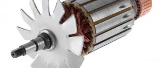
Each of these elements performs its own functions in the electrical circuit; a malfunction of each leads to a stop in the operation of the tool. For example, the armature, being a rotating element of the chain, is responsible for the rotation of the grinding disc. To make the disk rotate, the armature must spin at an even higher speed. Therefore, the higher the rotation speed of the armature, the greater the power of the tool.
The collector is the area on the anchor where all the power and control cables exit. Its task is to translate the signals passing through the windings into a language understandable to the engine and control unit. If you remove the case cover, its polished plates immediately catch your eye, especially since they are relatively large in size.
The purpose of electric brushes is to provide current supply to the commutator from the power cable. If they are in normal working condition, then an even glow will be visible through the ventilation hole. If the glow is not noticeable or it pulsates, then this is a sign that there are problems with the brushes.
The gearbox is a very important part not only of the electrical circuit, but also of the entire design of the angle grinder. Its purpose is to supply energy from the rotating armature to the grinding disc, thus ensuring its rotation. In fact, it is the gearbox that is responsible for the speed and power of rotation of the grinding disc of the grinder.
The stator is the most technically complex component in the electrical circuit of an angle grinder. All the windings of the armature and rotor are pressed into it, determining their rotation. The coil windings located in the stator are designed up to the last turn. If the stator fails, successfully rewinding it by a non-professional is a very rare case. Therefore, if the stator in an angle grinder breaks down, it is better not to risk it and have it repaired in a workshop.
How to assemble a regulator with your own hands?
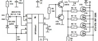
A simplified and quite reliable frequency converter for angle grinders is built with your own hands from available electrical parts. Below is a diagram that shows all the required components for mounting the device we are interested in on a printed circuit board.
- symmetrical triode thyristor (or triac, triac) DIAC (DB3);
- resistor (resistance) R1 (its parameters should be 4.7 kOhm);
- additional triac VT136/138 (TRIAC);
- capacitor C1 (400 V, 0.1 µF);
- additional resistance VR1 at 500 kOhm.
A similar scheme operates according to the following method.
- The charging time of the capacitor is modified by an auxiliary resistor (called a tuning resistor). When voltage is applied to the circuit, the triacs are in the closed position, and a zero voltage value is observed at the output.
- During the charging process of the capacitor, an increase in the voltage across it is observed, which leads to the opening of the DB3 triac. As a result of this, voltage falls on VT136/138. This thyristor element also opens, and electric current flows through it.
- After this, the symmetrical components close again and remain in a similar status until the capacitor is completely recharged in the opposite direction.
- Ultimately, at the output we obtain a deterministic signal of finite energy that is complex in configuration. Its exact range is determined by the period of execution of the functions of the circuit capacitor - auxiliary resistance - resistance R1.
Triacs are usually located on a printed circuit board. It is easy to create from PCB (multilayer pressed plastic consisting of heat-insulating fiber and foil is used). Individual craftsmen cut out the board using a cutter. It is practiced to place circuit elements using the hinged mounting method. Triacs are mounted only on an aluminum or copper heat exchanger. It acts as a good heat sink.
The assembled device is tested using an ordinary 40-60 W incandescent lamp. Connect it to the circuit and begin adjusting the glow power. If the brightness changes, then you did everything correctly. Now you can begin installing the regulator into the shell of the angle grinder. This is not very easy to do, since it is necessary to ensure that the auxiliary device does not interfere with you when using the angle grinder.
You will need to calculate the installation location of the homemade control device yourself, in accordance with the design features of the angle grinder. Installation of the circuit is done:
- in an additional box mounted on the unit body;
- into the holder handle;
- into a small empty niche (it is intended for cooling and circulating air masses) in the rear area of the angle grinder.
The circuit itself is connected to the device by integrating it into the electrical power channel of the angle grinder. You probably won’t have any difficulties with this.
Calibrating a new IAC
What should I do if the test reveals that the sensor needs to be replaced? It needs to be calibrated.
- We check the distance from the end of the rod to the mounting plate, it should be no more than 23mm.
- We disconnect the minus from the battery, de-energizing the ECU.
- Install the regulator.
- We connect the battery back.
- Turn on the ignition for 5 seconds without starting the engine. At this time, the IAC calibration occurs.
- Turn off the ignition to complete the calibration.
- We start the engine and observe the idle speed.
Now you know how the idle air regulator works, how to check it and, if necessary, replace it. As you understand, there is nothing complicated about this and all operations are accessible even to a novice car enthusiast.
Finally, a video about diagnosing IAC:
Previous post How to check gasoline injectors
Next entry Misfires - causes, diagnosis, elimination
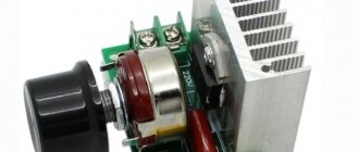
How to make a regulator from a dimmer?
A very effective and easy solution to this issue would be to create an external frequency converter. A dimmer can be used as a converter - a device for regulating the light level. When creating, you will need an electrical outlet and plug. It must be said that the implementation of such a device can be performed using different methods. Two are especially simple: with and without the use of a machine gun.
- Screw 2 wires to the ends of the electrical outlet so that one is longer. After this, connect the long end to one of the contacts on the plug. Fix the end of the 2nd wire to the dimmer contacts, and connect its other output to the 2nd contact of the plug.
- When using the 2nd option, it is necessary to make a number of modifications to the circuit, and specifically to place a machine on the cord between the plug and the dimmer. Basically, dimmers have ordinary switches, but we need an automatic one, which, if something goes wrong, will turn off our device from the mains.
So, the frequency converter of the angle grinder is ready, and for practicality it can be placed in a specialized housing or fixed on a wood panel. You just have to take into account that such a device is homemade, and when working with the electrical network, you need to be careful.
To learn how to make controller for an angle grinder with your own hands, see the video below.
Troubleshooting minor problems
If the grinder does not start when you press the “Start” button, it is quite possible that the cause of the breakdown is not too serious and the machine can be repaired on your own. There is a rule for repairing any power tool - move from simple to complex.
The device of an angle grinder's anchor.
In the above situation, in 9 cases out of 10, the cause of the malfunction will be a break in the electrical circuit in the area from the power source to the graphite brushes. The first step is to remove the casing and check with a tester whether electricity is supplied to the “Start” button. If electric current does not flow to the button terminals, then it is enough to replace the old electrical wire with a new one to repair the tool.
If current flows to the trigger, but does not go further, then the problem is in the start button itself. It needs to be replaced, but this should be done slowly. First you need to carefully disassemble the trigger mechanism, and do not be too lazy to mark the contacts to be removed. To replace a button that has become unusable, any button that is suitable in size and with similar parameters will do. You need to be especially careful when reconnecting the contacts, since their incorrect installation will most likely result in a burnt winding or a jammed armature.
Characteristic symptoms of malfunctions
Before it completely breaks down, the angle grinder gives signals about the beginning of problems.
Pay attention to the work of your assistant: you should be wary if:
- the brushes began to spark excessively;
- The grinder gets hot during operation ;
- the motor hums inside the housing when the tool is turned on;
- body vibration has become significantly greater during work;
- the grinder gearbox is cracking inside;
- the sound of bearings squeaking when spinning up or periodic wedging is heard when the rotor shaft rotates;
- The angle grinder is smoking, or there is an uncharacteristic smell of burning coming from it.
In order not to buy a new grinder, you need to be careful about the operation of the tool. In case of any deviations from the usual operation, begin troubleshooting, determine the cause and repair the power tool.
Checking the starting and control unit
Diagnostics of the electronic components of an angle grinder comes down to determining the serviceability of individual units, and repair (if there are no skills in radio engineering) means completely replacing them. The soft starter can be checked with a dial ammeter, comparing the current surge with and without it. To accurately diagnose the speed control unit under load, you will need an oscilloscope. Although, in order to understand whether it is in principle working or not, it is enough to simply observe the behavior of the angle grinder in different modes.
Electrical circuit diagram
In order to assemble a simple controller for an angle grinder, you need to purchase the parts shown in this diagram.
A small but very important detail! Why did the speed controller stop working on the Makita 9562?
- R1 - resistor, resistance 4.7 kOhm;
- VR1 - trimming resistor, 500 kOhm;
- C1 - capacitor 0.1 µF x 400 V;
- DIAC - triac (symmetrical thyristor) DB3;
- TRIAC - triac BT-136/138.
READ How to cut pipes smoothly with an angle grinder
Types of breakdowns in grinders
Typical minor damage
In the event of a malfunction, it is first necessary to eliminate elementary breakdowns:
- The grinder does not turn on. The angle grinder suddenly became faulty - it stopped turning on. In this case, you need to check the serviceability of the socket, then the plug and the power cord; perhaps the drive simply does not work due to the fact that no current flows into the product.
- The cable and plug are intact, but the drive does not work. You need to check the start button. It is easier to repair an angle grinder switch by purchasing a new button and replacing it. Since it is rarely repairable - mainly, the plastic switch rod inside breaks. If you want to experiment, you can disassemble it, numbering the contacts, and put everything back in its place so that after assembly there is no short circuit.
- The above parts are unharmed, but the angle grinder does not want to work - which means it’s time to check the brushes. Perhaps it's time to change them in the grinder. Brushes constantly heat up from work, so they wear out quickly and need to be replaced more often than other parts, and in pairs.
Major faults
Having ruled out all minor damage, you need to figure out why the tool does not want to turn on and how to repair it. Most likely, the malfunctions are serious and require additional knowledge. This happens if:
- the body is deformed;
- one of the bearings is jammed;
- the armature or stator does not work;
- the gear teeth of the gearbox are broken or worn out;
- the collector has failed;
- The control electronics sensor shows no signs of life.
If it is determined that the malfunction has occurred in the mechanical part of the angle grinder, then you need to pay attention to the condition of the large gear located on the shaft and the bushings. If the teeth are partially worn out or the shafts become wobbly, they must be replaced immediately.
The most common breakdowns
Grinder malfunctions happen quite often. Everyone who works with this tool knows about this. What goes wrong most often?
The spindle lock button is broken.
Just one awkward press on the spindle lock button while the disk is rotating leads to its breakdown. Sometimes it can be broken if it is used to remove a jammed disk. To prevent this from happening, you need to use an open-end wrench inserted into special holes near the place where the disk is attached.
How to assemble an adjustment circuit?
The traditional speed control circuit is quite simple: phase-pulse triggering of a triac, there are only a few parts in it. However, it does not behave very stably, so a professional tool uses this principle in a complicated version, with feedback and overcurrent protection (U2008B and U2010B microcircuits).
Now more advanced options are appearing, using PWM controllers. Their circuits are a little more complicated, but the main difficulties arise during setup and assembly. Instruments (oscilloscope) and the ability to work with expensive parts that are afraid of static charges may be required. In general, this is not for ordinary consumers.
Therefore, it is better to take an average solution: a version with a triac and a U2008 microcircuit; this circuit will only require proper assembly and inexpensive parts. It's a simple device, but for a household tool it works just fine.
Tips for choosing
How to choose the right angle grinder? To do this, you should use several basic criteria.
To choose the right tool, you need to decide on the specific type of work that will be performed with this tool. Grinders can be of different types: networked, with batteries, gasoline and pneumatic.
Network models are perhaps the most common. Such grinders operate from the home network, that is, from a simple outlet. Such tool models have high power, compactness and high rotation speed of cutting discs.
Rechargeable devices do not have this disadvantage. They have a special mount for power supplies that are charged from the mains. After charging, you can use this tool without any wires. Typically, such grinders have compact sizes and small diameter cutting discs. As a rule, such models cost more than standard tools. Also, their operating period is limited by the capacity of the power supply.
Gasoline models of grinders are rare. Such devices are characterized by large dimensions, because they require a fuel tank, as well as an internal combustion engine. Among the advantages, it is worth highlighting the high power of these models, a wide range of disk selection and autonomy. Negative aspects include their weight and bulk, high noise levels and, of course, additional fuel costs for operating the device.
Pneumatic models of angle grinders are often used for industrial purposes and very rarely for household work. These are unusual grinders that operate from a stream of compressed air and require a special compressor. In such models, the problem of overheating is completely eliminated, and the operating period can be limited only by the human factor. Also, such models are the lightest and quietest.
For simple work on processing and grinding surfaces, lightweight models of grinding machines with a small cutting wheel diameter are suitable. For work on cutting durable materials, it is worth selecting more powerful and, accordingly, bulky equipment with a large diameter of disks. Disc diameters can be from 125 (minimum size) to 230 (maximum size) mm - that is, the range of sizes is quite wide. The universal diameter of the cutting disc is 180 mm. With this wheel you can both process surfaces and cut material.
When choosing a disk, it is worth conducting a careful visual inspection. Even minor damage and chips can lead to extremely tragic consequences. By the way, almost 90% of accidents when working with an angle grinder occur due to a defect in the cutting discs.
Ease of use is also an important selection criterion. The grinder should be equipped with comfortable handles, should not slip out of the palm and have a lot of weight. Many grinders have an electronic relay to protect against power surges and overloads. This is a useful feature, so it is worth choosing a tool with such a fuse.
Features of checking the armature of an angle grinder with a tester
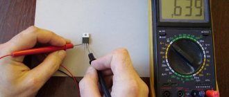
The diagnostic procedure will help to accurately determine the faulty part of the electric motor. A device that is available in the tool arsenal of many amateur electricians will allow you to check the armature of an angle grinder with a tester. Using the tester, you can check not only the armatures of angle grinders, but also the stator windings of other electric motors. In the video below you can see one of these homemade measuring devices in action.
When the tester is connected to the network, the indicator lights up. A red light without applying a technical device to the armature means the device is ready to perform the test. The working active surface of the measuring device has two points of contact with the test surface. One of them is a generator coil, the second is a communication curl coil. When checking the armature of an angle grinder with a tester, it is necessary to place this surface next to the groove being examined. Make sure that the sensors do not extend beyond the armature plates on both sides at the same time.
If the electrical part is in good condition or rewound, then when it is checked by a tester, the indicator opposite each of the grooves will light green. If there is a malfunction in the armature of the angle grinder, in particular, an interturn short circuit, a red light will appear on the device indicator at its location. Be careful when performing the diagnostic procedure to ensure correct contact of the surfaces when checking the angle grinder armature with a tester. Mechanical damage, which can be noticed visually without testing with a multimeter, should not be excluded as the reason for the failure of an angle grinder. They can be both significant and small. You may notice damage upon inspection after disassembling the angle grinder. It is necessary to diagnose such faults before checking the armature for an interturn short circuit.
If you do not have experience in disassembling power tools or preparing to work with measuring instruments for testing an armature with a multimeter and are not confident in your own abilities, you should not interfere with the design of the angle grinder. Do not experiment to avoid damaging the angle grinder. In this case, to find the cause of the breakdown of the power tool and check the armature of the angle grinder with a tester, it is better to contact a service center or qualified mechanics who specialize in equipment repair.
The main malfunctions of an angle grinder and their causes
According to statistics, most cases of angle grinder failure are associated with the electrical part of the device. Some damage may be minor, which allows you to repair the angle grinder yourself. But, for example, if the motor windings burn out, only a specialist can repair an angle grinder.
Grinder won't turn on
The reasons that the angle grinder does not turn on may be the following:
- the electrical plug is faulty;
- the electrical cable is faulty;
- the start button is broken;
- the contact between the power cable and the button is broken;
- break in the contact wire of the electric brush;
- severe wear of electric brushes;
- failure of the rotor or stator windings.
The angle grinder does not develop speed
The reasons why the angle grinder does not gain momentum can be different.
- Damage to the speed control unit. To check this version, you need to connect the device’s motor directly, bypassing the regulator, and check the operation of the device.
- Failure of the electrical cable due to constant kinks or mechanical damage. Because of this, the damaged wire begins to heat up under load, and engine speed drops.
- Collector contamination with dust. Contaminants must be removed with alcohol.
- Problems with brushes. They may be worn out or have a short contact wire as shown in the following photo.
Although the brush is half worn out, it is still fully functional. In this case, a short contact wire prevents the spring from pressing the electrode to the collector. This situation may also be the reason why the angle grinder stopped working normally.
The electric motor is heating up
The reasons why the angle grinder is heating up may be the following.
- Incorrect operating mode of the device. As a result of overloads, the electric motor can become very hot, which often leads to burnout of the windings.
- Destruction of bearings located on the armature. As a result, the rotor clings to the stator, engine operation becomes difficult, and the windings overheat. The problem is solved by replacing the bearings.
- Clogged ventilation ducts through which air flows to cool the engine. The ventilation openings must be cleared of dust.
- Damage to the impeller used to cool the engine. It is installed on the rotor, on the side opposite to the collector. If the impeller is broken, it must be replaced with a new one.
- Interturn short circuits of stator and rotor windings. It will be necessary to rewind the reels or replace these parts with new ones.
Bulgarian sparkles
If you notice strong sparking when you turn on the angle grinder in the place where the collector is located, then the reasons for this trouble may be the following.
- Damage to the armature winding: break of one or more sections of the winding, interturn short circuit. With such breakdowns, increased noise appears, engine speed drops and brushes burn.
- The contact between the collector plates and the winding is broken.
- Weak brush pressure. During long-term operation of the angle grinder, the springs overheat and can “anneal”, thereby losing their elasticity.
- Engine rotor imbalance.
- Damage to the cylindrical surface of the collector. This sometimes happens after rewinding, if the armature is not turned on a lathe, but is immediately installed in the machine. In this case, you can also observe that the brushes spark excessively.
- The insulation between the collector lamellas is broken. There may also be clogging of the track grooves with graphite or a breakdown between the lamellas.
- Bearing wear, which causes the rotor to run out, also causes the brushes to spark heavily.
- Violation of the geometry of the armature shaft. This usually happens when the electric motor is disassembled carelessly and the shaft bends.
- Wrong brand of graphite brushes installed. Brushes are selected based on the expected speed and voltage.
- Raising one or more lamellas causes the brushes to quickly burn out. This happens due to engine overheating during prolonged operation. As a result, the glass melt, which serves as the basis of the collector, softens and the lamellas begin to rise. Due to the fact that the slats are raised, the brushes wear out very quickly.
Checking the angle grinder's anchor with a tester - possible diagnostic results
Among the most common causes of equipment failure, the most common is interturn short circuit of the angle grinder armature. It can be detected - ringed - using a tester. A multimeter is an electrical measuring instrument that includes the functions of an ammeter, voltmeter and ohmmeter. They can not only check for the presence of an interturn short circuit in the winding of the angle grinder, but also measure the resistance between the lamellas. A simpler device is a tester. By checking the angle grinder armature with it, you can detect faults caused by a short circuit.
Checking the health of the stator
The stator is the stationary part of the electric motor that creates an electromagnetic field in which the rotor rotates. The cause of failure is often either a short circuit or a break in the turns of the stator winding (coil).
- water ingress;
- overheating caused by overloading the angle grinder;
- power surge;
- sharply pulling the tool plug out of the socket.
Signs indicating stator failure:
- appearance of smoke;
- smell of burnt insulation;
- overheating of the grinder body;
- stopping the rotation of the shaft or slowing it down;
- sudden spontaneous increase in speed.
How to ring an armature with a multimeter?
To perform this procedure, you will need the electrical measuring instrument itself and tools to disassemble the device. How to ring an armature with a multimeter - instructions:
- Prepare your work surface. There should be enough space to accommodate the necessary tools and parts removed from the device.
- Disassemble the angle grinder and remove the anchor.
- Clean the part from dirt and dust.
- Using the recommendations in the video presented, you can independently ring the armature with a multimeter.
At the initial stage of diagnosis, the value of the measuring device is set at 200 kOhm. If your multimeter does not have such a scale, then you can limit yourself to 20 kOhm. To test the armature, one probe of the measuring device is applied to the ground, and the second is touched to each of the plates. If no indicators appear on the scale of an analog multimeter or the digital screen, most likely there is an interturn short circuit in the armature winding. You can accurately diagnose the problem using a special device that is available to professional locksmiths.
Repair of grinder PIT. The speed is not regulated.
Features and service life
They can operate on direct and alternating current.
To power them, in most cases, a conventional electrical network of 230 V 50 Hz is used. Previously, a 380 V network was used for professional tools. Now, with the increase in consumer power in single-phase networks (offices and residential sector), professional power tools for 220 V have also appeared.
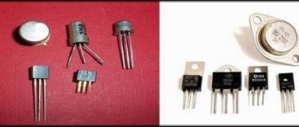
Commutator motors have high torque and starting torque, are compact, and can be easily manufactured for higher voltages. Torque is key here. With the low weight of the machine, it is just suitable for hand-held power tools. But such electric motors have disadvantages and weak points. One of these weak points is the brush assembly.
Brushes made of pressed graphite with fillers rub against the copper plates of the commutator and are subject to mechanical wear and electrical erosion. This leads to increased sparking and increases the fire and explosion hazard of the power tool. Ingress of mineral dust will accelerate wear. Although the fans provided in the design blow air outside, dust and cement can easily get inside. During downtime, if the tool is placed poorly, dust can easily get inside. In practice this is a constant occurrence.
Extruded graphite motor brushes
Another disadvantage of power tools is frequent gearbox breakdowns. This happens precisely because of the high starting torque. Advantage turns into disadvantage. If the gearbox breaks down, you have to change the tool; they usually cannot be repaired. Unfortunately, the industry, in an effort to reduce production costs, does so at the expense of quality. If you want to use a good power tool, pay a lot of money.
What problems in the operation of the device can be detected when checking the armature of an angle grinder with a tester?
If you have sufficient knowledge to properly disassemble a power tool, then in some cases you will be able to diagnose the cause of the device failure yourself. Checking the angle grinder's armature with an interturn short circuit tester will allow you to determine further actions regarding the detection of malfunctions or repair of equipment. If the part is not damaged but the tool still does not work, contact qualified service personnel for assistance. Did checking the angle grinder's armature with a tester allow you to accurately detect the cause of equipment failure? If you have the necessary tools, you can repair equipment yourself in the following cases:
- If the winding is damaged in the upper visible layers, you can try to solder it. This anchor will last for some time. After sealing, it must be checked or tested with a multimeter;
- When an interturn short circuit occurs, the winding must be rewinded or the armature must be replaced.
READ How to Test a Chainsaw Ignition Coil with a Multimeter Video
Diagnosis of breakdown and repair of an angle grinder can be performed under voltage. For your own safety, delegate this work to professionals.
To come in
Already registered? Sign in here.
There are currently 0 users on the page
There are no users viewing this page.
The grinder, being the most popular tool in the house, is subjected to considerable loads and intensive use. Because of this, after some time it happens that when starting the engine, jerks, a burning smell and other malfunctions appear, suggesting that the angle grinder (angle grinder) has broken down. But you shouldn’t immediately take the device for repairs or buy a new one. Most malfunctions of this device can be resolved independently.
Do-it-yourself Bosch grinder repair
Angle grinders (angle grinders, angle grinders) under the German brand Bosch are distinguished by high quality, reliability and durability. The main competitive advantage of Bosch angle grinders lies in the widespread use of innovative technologies in the manufacture of the product.
But German quality cannot resist Russian negligence. Incorrect use of the tool, untimely replacement of lubricant, carbon brushes, bearings leads to tool failure.
In order to repair a Bosch angle grinder, you can go in two ways: take the angle grinder to a service center or repair the Bosch angle grinder yourself.
The first option is more expensive and not always of high quality. The second option can only be implemented if the consumer has a strong desire to figure everything out on their own.
The Bosch angle grinder diagram will help you carry out the repair yourself.
Bosch grinders are conventionally divided into low-power ones up to 1000 W, and powerful ones over 1000 W and are marked GWS 7-125, GWS 20-230 or others.
The first number 20 or more indicates the power of the instrument is more than 1000 W. The second number 230 certifies that this is the maximum diameter of the cutting wheel.
The first number up to 20 indicates the power of the tool up to 1000 W, and the second indicates the maximum diameter of the cutting wheel up to 125 mm.
Electronic unit in an angle grinder
The electronic unit allows you to combine controller and soft start into one. The electronic circuit is implemented on the principle of pulse-phase control with a gradual increase in the opening phase of the triac. Grinders of different power and price categories can be equipped with such a block.
An angle grinder, which received the nickname “ Bulgarian ” in the post-Soviet space, was something every owner wanted to have in his home workshop 3-4 decades ago. Then for most people it really was a dream, since only one produced this electric instrument in the Bulgarian city of Plovdiv (hence the popular name). And although over the past time the number and range of grinders have grown incredibly, the main components of the tool’s design have not changed.
Grinder Forte 125 does not turn on. replacing the triac.
Grinders are used not only for grinding and polishing surfaces, but also for processing metal and concrete (using diamond or abrasive wheels).
Tools needed for repairs
To repair a Bosch angle grinder, you cannot do without tools. Let’s make a reservation right away: if you have a screwdriver, this will significantly speed up the process of disassembling and assembling the tool.
But you can get by with a set of screwdrivers, preferably with a ratcheting mechanism. You cannot do without an open-end wrench, which you will use to unscrew the nut securing the drive helical gear.
To remove bearings, it is better to have a special puller.
Diagnostics of the electrical part can be carried out using a tester or a device for determining short circuits of turns.
It is especially useful in that it allows you to determine whether the rotor or stator is faulty without removing the assembly.
The Bosch angle grinder diagram will help you carry out the repair yourself, and these instructions will help you adequately cope with any problem.
Rotor assembly
Assembling the rotor consists of pressing bearings onto it and installing the impeller. Lubricated bearings are pressed onto the shaft using a wooden extension. The bearing near the collector is covered with rubber protection. This is the general algorithm for assembling the rotor shaft.
Some models of Bosch angle grinders have their own characteristics.
How to remove the drive gear of a Bosch angle grinder
The drive gear pos. 27 is removed from the rotor shaft in the following sequence:
- Hold the rotor with your hand and, using an open-end wrench, unscrew the nut pos. 45 counterclockwise;
- remove the washer pos. 59.;
- pull out the drive helical gear pos.27.
Visually check the integrity of the gear teeth and contact patch.
If the gears are heavily worn (licked), or there are chipped teeth, they must be replaced. Moreover, gears are always replaced in pairs.
Low-power Bosch angle grinders use a needle bearing as a support bearing in the gearbox.
When repairing Bosch angle grinders yourself, strictly follow the included instructions. If you need to remove a needle bearing from its housing, some quick thinking is required. Its dismantling is carried out only when destroyed.
To remove a damaged bearing race, you can use a proven method.
Select a tap with a diameter slightly larger than the inner diameter of the damaged needle bearing race. The tap is secured in the screwdriver chuck and carefully screwed into the holder at low speeds. When the tap reaches the bottom of the gear housing, it will begin to lift the cage.
In addition to the needle bearing of the spindle shaft, Bosch angle grinders use two more bearings mounted on the rotor shaft.
Assembling the grinder
The assembly of the grinder begins with an examination of all parts, assemblies, bearings, and gears.
Pre-prepare the workplace with proper and good lighting, place tools, lubricants, and napkins.
Design features of the Bosch angle grinder
A design feature of the Bosch grinder is represented in the use of a gearbox as a support bearing for the driven helical gear of a needle bearing. In Bosch rotary hammers, the driven gear is attached to the spindle shaft by pressing.
In low-power Bosch angle grinders, in which spur gears are installed in the gearboxes, the installation of shims is provided. This design allows you to restore the functionality of the gear contact by reducing the thickness of the gasket. At high tool speeds, helical gears wear out significantly less than spur gears.
The work environment for grinders is most often a dusty space. Dust is the main danger leading to failure of power tools, grinders and grinders.
Do-it-yourself disassembly of a Bosch angle grinder
For the owner of a power tool, knowledge of its structure and the ability to disassemble it is a mandatory task.
Knowing the procedure for disassembling an angle grinder allows you to independently carry out work such as changing grease, changing bearings and carbon brushes.
To disconnect the gearbox housing pos. 821 from the stator housing pos. 888, you need to disassemble (remove) the body of the grinder handle pos. 24.
This operation must be performed to remove the carbon brushes pos. 810 holding the rotor commutator.
At the second stage, unscrew 4 (four) screws, pos. 61, securing the gearbox and stator housings.
Having pulled out the rotor together with the gearbox, begin disassembling the gearbox.
Repair of a Bosch angle grinder begins with disassembling the gearbox pos. 821. Disassembling the gearbox begins with unscrewing 4 (four) screws, pos. 60. As a rule, the screws are screwed in with sealant at the factory. You will have to make some effort.
Let's note it right away! Low-power Bosch angle grinders use spur gears in the gearbox. Grinders with a power of over 1000 W use helical gears in their gearboxes.
How to determine whether a rotor is faulty
Rotor repair is a complex technological process accessible to skilled craftsmen.
A rotor malfunction is indicated by a drop in engine speed and the appearance of a long sparkling trail on one of the brushes. This is the first sign of a short circuit in the armature winding turns.
It is preferable to carry out rotor repairs in special workshops. Or you can rewind it yourself if you decide to repair the Bosch angle grinder yourself.
The dark color of the rotor winding and burnt commutator lamellas indicate a short circuit in the rotor circuits. The malfunction can only be eliminated by replacing it with a new rotor.
Sources:
https://vahatehnika.com/boLGarka/kak-umenshit-oboroty-na-boLGarke.html https://toolparts.com.ua/novosti/proverka-iakoria-testerom-rekomendatsii-spetsialistov https://sdelalremont.ru/ remont-boLGarki-Bosch-svoimi-rukami.html
Mechanical breakdowns and their elimination
Mechanical failures of angle grinders include the following.
- Worn motor armature bearings. Typically, when the bearings wear out, you may experience strong vibration while the machine is operating. In addition, grinding and other noises may be heard. Sooner or later, the bearing will collapse, and the spilled balls will fall on the gears of the gearbox. If this happens, then in addition to the bearing, the gears will also have to be replaced. Of course, it is better not to wait for this problem, but to replace it at the first sign of bearing failure. How to get to this part of the angle grinder was described above.
- Worn ball bearing or plain bearing of the gearbox. As in the previous case, when you turn on the device, vibration will be felt and noise will be heard that is unusual for the normal operation of an angle grinder. To prevent further damage to the gearbox, it is necessary to replace the faulty part.
- Reducer gear wear. Gears wear out quickly due to insufficient lubrication. For the same reason, the gearbox heats up. It is necessary to monitor the condition of the lubricant inside the gearbox and change it if necessary. How to disassemble the gearbox was described above. You need to use lubricant specially designed for angle grinder gearboxes, and you can buy it at points where this tool is sold. If for any reason the teeth of at least one gear are broken, then the entire set of gears (a pair) needs to be replaced.
Mechanical faults can also include a broken shaft lock. In order to replace the retainer, you will need to disassemble the gearbox and remove the large gear.
Checking an Individual Regulator
Checking the voltage regulator of the G-222 generator: 1 - battery; 2 - voltage regulator; 3 - control lamp.
As a rule, separate voltage regulators were installed on old cars, including domestic VAZs. But some manufacturers continue to do this to this day. The verification process is similar. To do this, you need to have a power supply with a voltage regulator, a 12 V light bulb, a multimeter and a directly tested regulator.
To check, you need to assemble the circuit shown in the figure. The process itself is similar to the one above. In normal condition (at a voltage of 12 V), the light bulb lights up. When the voltage value increases to 14.5 V, it goes out, and when it decreases, it lights up again. If during the process the lamp lights up or goes out at other values, it means that the regulator has failed.
Checking relay type 591.3702-01
Relay test diagram type 591.3702-01
You can also still find a voltage regulator of type 591.3702-01, which was installed on rear-wheel drive VAZs (from VAZ 2101 to VAZ 2107), GAZ and Moskvich. The device is mounted separately and installed on the body. In general, the test is similar to that described above, but the differences are in the contacts used.
In particular, it has two main contacts - “67” and “15”. The first of them is a minus, and the second is a plus. Accordingly, to check it is necessary to assemble the circuit shown in the figure. The verification principle remains the same. In normal condition, at a voltage of 12 V, the light bulb lights up, and when the corresponding value increases to 14.5 V, it goes out. When the value returns to its original value, the light comes on again.
A classic regulator of this type is a device of the PP-380 brand, installed on VAZ 2101 and VAZ 2102 cars. We provide reference data regarding this regulator.
| Adjustable voltage at regulator and ambient temperature (50±3)° C, V: | |
| at the first stage | no more than 0.7 |
| on the second stage | 14,2 ± 0,3 |
| Resistance between plug “15” and ground, Ohm | 17,7 ± 2 |
| Resistance between plug “15” and plug “67” with open contacts, Ohm | 5,65 ± 0,3 |
| Air gap between armature and core, mm | 1,4 ± 0,07 |
| Distance between second stage contacts, mm | 0,45 ± 0,1 |
Testing a three-level relay
Regulated power supply
Some car owners install on their cars, instead of standard “chocolate bars,” three-level relays, which are technologically more advanced. Their difference is the presence of three voltage levels at which the battery power is cut off (for example, 13.7 V, 14.2 V and 14.7 V). The appropriate level can be set manually using a special regulator.
Such relays are more reliable and allow flexible adjustment of the cutoff voltage level. As for checking such a regulator, it is completely similar to the procedures described above. Just do not forget about the value that is set on the relay, and accordingly, check it with a multimeter.
Generator check
There is one method by which you can check the performance of a car generator equipped with a regulator relay 591.3702-01 with diagnostic elements. It is as follows:
- disconnect the wires that went to pins 67 and 15 of the voltage regulator;
- connect a light bulb to it (excluding the regulator from the circuit);
- Remove the wire from the positive terminal of the battery.
If, as a result of these actions, the engine does not stall, then we can say that the car’s generator is in order. Otherwise, it is faulty and needs to be checked and replaced.