Rotor for INTERSKOL USHM-2300M, HAMMER. Photo 220Volt
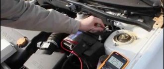
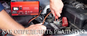
When an angle grinder fails, diagnostics are performed to identify the causes . One of them may be a breakdown of the armature (rotor) of the electric drive. check the serviceability/failure of this rotating assembly yourself . It is necessary to have in your arsenal only simple devices for testing the electrical circuit.
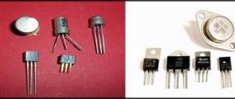
Device
To correctly diagnose armature faults, it is important to know the device and the principle of its operation . The main elements of the armature are a round core, consisting of a set of electrical steel plates and a winding wound into its grooves in a certain way. Two armature windings are placed in each of the grooves according to a special pattern . The first and last turns of one of the windings are in the same groove and are closed to one lamella.
Rotor for Makita angle grinder 9069 MAX. Photo 220Volt
The core is pressed onto the rotor , which rotates under the influence of forces arising in the electromagnetic field formed by the armature windings and the stator coils working in tandem with it. In grinders, the anchor is an assembly unit with a drive gear located at one end of the shaft, and a commutator unit at the opposite end.
Disassembling the grinder
How to check the stator of an angle grinder (grinder)? You need to start by disassembling the device. To do the job you will need a screwdriver.
Procedure:
- Remove all unnecessary parts from the surface on which the angle grinder will be disassembled.
- Remove the scratch disk.
- Unscrew the screw securing the casing.
- Unscrew the screws securing the plate.
- Move the cover towards the cord.
Main parts of the angle grinder electric motor:
- rotor (armature);
- stator;
- collector;
- brushes.
The stator is located on the outside of the engine, on top of the rotor. To get the stator, you will first have to remove the brushes, then remove the gearbox and after that pull the armature out of the grinder body. The rotor must be removed from the stator before checking. It is recommended to carry out the inspection in bright light. First of all, you need to carefully inspect the winding and make sure that there are no visible breaks in it. If the inspection does not reveal the cause of the stator malfunction, then a special test device will be needed.
Causes of malfunctions
The causes of rotor failure may be improper operation of the power tool, which is represented by the following factors:
- the permissible time of continuous operation has been exceeded, which is one of the main reasons for the failure of household angle grinders;
- carrying out work in aggressive environments with the presence of sand, moisture, abrasive dust and other similar materials;
- work in conditions exceeding the permissible load;
- some mechanical faults affect the imbalance of the rotating rotor, which ultimately affects the normal functioning of the rotor electrical circuit;
- instability of the mains voltage while working with a power tool.
Serviceable rotor for Bosch angle grinder GWS6-100/GWS 850 MAX. Photo 220Volt
The operation of a power tool associated with the action of these factors leads to the following malfunctions :
- breakage of coil conductors;
- short circuit between turns due to burnt insulation;
- the insulation loses its properties, which can cause breakdown of the winding to the core body;
- violation of collector contacts;
- Particles of burnt insulating varnish or melted solder that get into the gaps that come into contact with the rotating rotor can cause mechanical damage to the elements of the angle grinder: cracks, chips, deep scratches.
- The collector lamellas wear out unevenly and carbon deposits form on them due to a short circuit.
This mainly happens when the grinder's commutator engine operates for a long time without a rest break. The winding insulation from heating loses its characteristics and melts, which leads to a short circuit of the turns. The contacts connecting the armature winding to the commutator lamellas can become unsoldered, the electric current is interrupted and the electric drive stops.
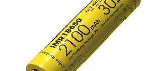
Checking with a short-circuited turns indicator (SCI)
There are anchors where the wires connected to the collector are not visible due to being filled with an opaque compound or due to a bandage. Therefore, it is difficult to determine the commutation on the commutator relative to the slots. An indicator of short-circuited turns will help with this.
This device is small in size and easy to use.
First check the anchor for breaks. Otherwise, the indicator will not be able to detect a short circuit. To do this, use a tester to measure the resistance between two adjacent lamellas. If the resistance is at least twice the average, then there is a break. If there is no break, proceed to the next step.
The resistance regulator allows you to select the sensitivity of the device. It has two lights: red and green. Adjust the regulator so that the red light starts to light. On the indicator body there are two sensors in the form of white dots located at a distance of 3 centimeters from each other. Attach the indicator with the sensors to the winding. Rotate the anchor slowly. If the red light comes on, it means there is a short circuit.
How to check the serviceability and ring the rotor of an angle grinder at home, video
At home, there are the following methods for diagnosing an anchor:
- visual inspection;
- using a multimeter;
- a light bulb and two wires connected to it;
- devices specially designed for checking the integrity of windings (short circuit indicator, armature testing device and others).
For more information about the types of diagnostics, see the information below, where there is a video.
Visual inspection
Even if you have a full arsenal of instruments for testing the armature electrical circuit, never neglect a visual inspection - the mandatory first step of the entire diagnostic process. A careful look will find signs by which a user who knows the design and principles of operation of the rotor will determine the nature of the malfunction.
Charred marks and the presence of a specific odor cause burnt insulation and ultimately damage to the winding wires. You should pay attention to crumpled or swollen coils , which may indicate the presence of breaks in a given location. solder particles on , which can cause a short circuit.
Violations in the contacts of the windings with the collector can be detected by burnt out lamellas . Damage to the collector itself is visually diagnosed - raised, worn or burnt plates.
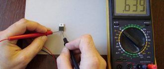
Tester, multimeter
The device multimeter or its other name is a tester for measuring electrical parameters: current, voltage, resistance - can be used to search for breaks in winding wires or breakdowns in the core body.
In the following video, the author offers a diagnostic option from simple to complex. Using a multimeter, the stator is first tested. It is much easier to check it than the rotor. If there are no breaks on the stator and no breakdowns of the winding to the housing, then we can conclude that the armature is faulty. Next, you should diagnose it in more detail, determining the exact type of defect and determining the method of elimination. A continuity test is carried out with a multimeter in the “resistance test” mode with the minimum measurement scale set (up to 200 Ohms).
This video, like the other, shows the process of determining winding breaks, which is really quite labor-intensive, since measurements are taken between each pair of lamellas along the entire contour of the collector. In this case, on an armature that does not have breaks in the windings, all multimeter readings should not differ from each other within 0.1 Ohm. It is much easier to check the breakdown of the windings on the body by placing one probe on the core body and the other on the collector plates. The multimeter scale should not respond with any readings.
It is impossible to determine the interturn short circuit with a multimeter. Other devices are used here.
Interturn short circuit indicator
In the following video, the author tests a device for determining the interturn circuit (IMC) of his own making. The principle of its operation is based on the interaction of electromagnetic fields created by the coils of the IMZ device and the windings of the armature or stator. In the presence of an interturn short circuit, the parameters of the magnetic field of the device change, which is recorded by a light indication - the red light comes on, and if there is no short circuit, the green light lights up.
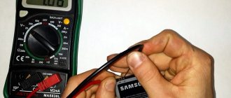
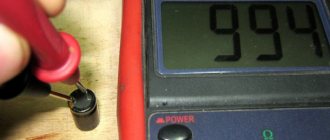
A light bulb
If you don’t have a multimeter, you can test the electrical circuit of the rotor using a 12 V light bulb. First , connect two wires to the light bulb itself. The power source is a regular battery, to the ends of which you should connect the ends of the break of one of the wires connected to the light bulb. Such an amateur “device” is used instead of a multimeter, where the ends of the wires are applied to the lamellas without touching each other. Carefully rotate the armature to monitor the brightness of the light bulb. If it is constantly on without blinking, then there are no breaks in the winding.
Breakdown of the winding to the core body is checked by connecting one of the ends to the collector and the other to the core or shaft. If the light comes on, it means there is a breakdown of the winding to the housing.
Throttle
The presence of an interturn short circuit in the rotor can be determined using a device for testing armatures. It is a transformer with one primary winding ; in fact, it is a wire wound on a ferromagnetic core. At the same time, it has a triangle cutout in it, in which the rotor under test can be stably positioned. Its winding begins to work as a secondary coil of a transformer.
In the presence of an interturn short circuit, the parameters of the rotor magnetic field have greater intensity; a metal strip placed on the surface of the core will vibrate and, when magnetized, will be attracted to the core body. The plate will move freely on the rotor core body if it has normal windings without defects.
Device for testing armatures and stators of electrical machines
Another device with which you can check the stator of an angle grinder is a device for checking armatures and stators of electrical machines PUNS 5. The device has light and sound alarms, allows you to detect interturn short circuits of windings, breaks, and measure the insulation resistance of coils.
The device operates in two modes - “armature” and “stator”. The mode is changed using a switch. The device is equipped with a convenient device for installing and fixing the engine being tested. It consists of two legs attached to a shaft. The jaws move freely along the shaft, allowing you to change the distance between them and test motors of different sizes. The check is carried out using two probes. The presence of a break or short circuit in the stator winding is indicated by special red LEDs and an audible signal. The testing procedure is described in more detail in the instructions for the device.
Repair, replacement, rewind
After diagnosing and determining the types of rotor faults, a decision on repair methods follows . It is possible to do the repair yourself, which will involve rewinding the armature yourself. If this option seems labor-intensive and complicated, you can follow a simplified scheme and replace the burnt out rotor with a new one that matches the model of the angle grinder. The simplest, but also expensive option is to contact a special service department .
When making a decision about repairing an anchor with your own hands, the information available in the articles “How to remove an anchor from an angle grinder”, “Replacing and repairing an angle grinder’s anchor”, “Rewinding an angle grinder’s anchor with your own hands” will help.
Sections: Do-it-yourself repair of grinders, Grinder anchors
Previous article: Do-it-yourself repair of the stator of an angle grinder Next article: Rewinding the armature of an angle grinder with your own hands
How to quickly determine the turn closure of an armature.
If the balancing of the armature is not disturbed, and the problem is solely in the damaged windings, then there is an option to return such an armature without the help of others by rewinding the coils. Rewinding a rotor at home requires great patience and accuracy.
The master must have the ability to work with a soldering iron and devices for diagnosing electronic circuits. If you are unsure of your own abilities, it is better to take the engine for repairs to a workshop, as it is also called, to change the entire armature without the help of others.
Stage 1. Visual inspection of the tool
Very often there are situations when the tool still works, but no longer as it should. And in 30% of cases the culprit is a burnt anchor. This can be detected visually, even before opening the case.
Indirect signs of a “tired” electric motor armature are the following problems:
- When the electric motor is running, very strong sparking is visible on the commutator.
- When trying to start a grinder (drill, circular saw, etc.), a severe voltage drop is observed (the lighting blinks).
- Starting the electric motor is accompanied by sharp jerks.
- There is a characteristic smell of burnt wiring coming from the housing.
- The tool does not gain the same power.
Please note that more than half of these signs may also indicate simple wear of the motor brushes. If they are worn out or crumbled, then the anchor most likely has nothing to do with it. We replace them with new ones, clean the collector from graphite deposits, and calmly continue working. If the brushes look intact, and the above symptoms are observed, with an 80% probability we can say that the problem is in the motor armature.
If the power tool shows no signs of life at all, there may be many more reasons, and more than just checking the armature will be needed.
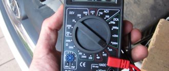
Application of a multimeter
Now we need to check the possibility of a break in the stator windings. On the multimeter scale, set the switch to the resistance measurement sector. Without knowing the measurement value, we set the maximum value for your device. We check the functionality of the tester.
We touch each other with our probes. The arrow of the device should show 0. We carry out the work by touching the terminals of the windings. When an infinite value is shown on the multimeter scale, the winding is faulty and the stator should be rewound.
We check the possibility of a short circuit to the housing. Such a malfunction will cause a decrease in the power of the angle grinder, the possibility of electric shock and an increase in temperature during operation. The work is carried out according to the same scheme. Turn on the resistance measurement on the scale.
We place the red probe on the winding terminal, and attach the black probe to the stator housing. If the winding is short-circuited to the housing, the resistance value on the tester scale will be less than on a working one. This malfunction requires rewinding of the stator windings.
It's time to take measurements and check whether there is an interturn short circuit in the stator winding. To do this, the resistance value on each winding is measured.
We determine the zero point of the windings by measuring the resistance for each of them. When the device shows the lowest winding resistance, it should be changed.
Common breakdowns
Regardless of the build quality and manufacturer, the following malfunctions occur quite often:
- the electric motor fails due to a broken armature or stator;
- extreme wear of brushes;
- bearing problems;
- The speed control button does not work;
- the contacts of the start button oxidize or burn out;
- failure of the chuck clamping the drill due to wear of the jaws.
If you decide to repair an electric drill yourself, you first need to diagnose and find the fault. It is rarely possible to repair a faulty part on your own; as a rule, it is simply replaced with a new one.
Installation and assembly of a new rotor
Replacing the rotor does not require special knowledge and can be done by any user.
The rotor is inserted into the mechanical block using a helical gear until it fits snugly.
Remember! It is very important to correctly install the bearing pos. 56 and the rubber ring 10 pos. 77. In the Makita 2450 hammer drill, bearing 607LLB pos. 56 or the domestic equivalent 80017 is used on the rotor on the commutator side, and bearing 609LLU pos. 51 or analogue 80019 is installed on the impeller side pos. 53
Correctly installed rubber ring 19
Having installed the rotor and covered it with the housing, replace the electric brushes and check the functionality of the hammer drill.
A grinder is a construction tool used in cutting and processing the edges of various hard materials, such as stone, metal, wood, etc.
Rotor is a part of the grinder engine that rotates during the working process, driving other components and parts of the electric tool.
The quality of cutting and grinding performed by the tool and the service life of the device depend on the operation of this important part.
Monitoring the operation of the rotor is carried out in two ways - a preventive inspection and by determining the cause of the malfunction if a breakdown has already occurred.
Standard diagnostics
While you take the diagnostic device, inspect the anchor. There is damage here. If the wiring is melted, the burnt insulating varnish will leave black marks and a different specific odor. We encounter bent and crumpled turns or conductive particles, for example, solder residues. These particles are a prerequisite for a short circuit between the turns. The lamellas have curved edges, called cocks, to connect to the winding.
Due to disruption of these contacts, the lamellas burn out.
Other damage to the collector: raised, worn or burnt plates. Graphite from the brushes can accumulate between the lamellas, which also indicates a short circuit.