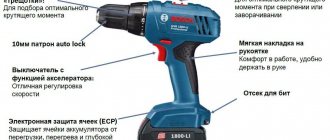
Now you have to use a soldering iron and unsolder the two elements from each other, as shown in the figure. Screwdriver design: 1 - speed controller with reverse, 2 - electric motor, 3 - gearbox.
Resistor Rx sets the highest current.
The graph shows how the temperature of the element temperature, the voltage at its terminals voltage and the relative pressure relative pressure change during charging. It can monitor battery parameters and, if necessary, reduce the current automatically. WE MAKE A SIMPLE BATTERY CHARGER with auto shutdown when fully charged
The electrical signal is supplied directly to the engine rotor through the commutator. Next, you need to carefully assemble the screwdriver button, install it in place and test it.
When the breakdown occurred, I was on business in Orenburg and therefore contacted the service center for repairs there.
Replaceable battery.
The rather miniature size of this tool assembly is achieved using microfilm technology.
We visually inspect the condition of the button for dirt and damage. repairing a screwdriver, replacing the power button with your own hands
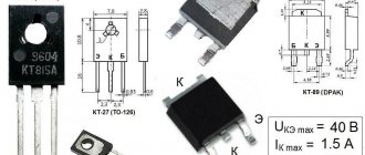
Transistors STP60NF06. Screwdriver repair
At some point, during a cold start (after storage), the screwdriver began to ignore the force of pressing the button, immediately turning on the maximum speed.
After rummaging around on the net, I decided to first clean the insides of the button, since there was a possibility that the problem was the accumulated metal filings on the sliding contacts. I still don’t understand whether this is true, because during the assembly process I mixed up the polarity of the insert diode, which led to the transistor burning out. So I had to order a new one. To understand what I did wrong, I found a diagram of a button on the same chip as mine (GS069). It is slightly different; instead of a resistive track (potentiometer), I have tracks for resistive dividers on the board, but otherwise the circuit is the same. I noticed in time that both diodes in the diagram are shown with reversed polarity, otherwise it would have burned out another transistor. The mentioned insert diode does not have any markings and looks like a small iron washer with insulation around the perimeter; next time I disassemble the button, I will take a photo and show it here. Polarity is determined by a multimeter in dial mode.
I saw ready-made assemblies with a transistor and a button in a local store, they cost from 400 rubles. Perhaps the entire assembly should have been replaced at once, given the noticeable wear of the contacts, but I decided to save money; it was better to buy a normal tool for the money. Or, for a thousand and a half, you can rent just another Chinese screwdriver for the season with new gears, a motor, and a button. Replace it with a good battery and continue buzzing quietly.
At the time of delivery of the new transistor, I installed the less powerful IRFZ24N (17 A versus 60 A and 55 W versus the old 110 W); I couldn’t find anything else. The transistor is the same type, I was not afraid of compatibility. In all modes with the limit clutch turned on, the screwdriver does not develop enough power so that even such a relatively weak transistor is not enough. The mosfets parallel well; for reliability, you could assemble a sandwich from a couple of IRFZ24Ns.
I temporarily decided not to use the tool in difficult situations when it was necessary to remove restrictions, but my plans were disrupted when I urgently had to unscrew a hefty screw. At the maximum limit, the protection (ratchet) was constantly activated, the screw did not budge. I took a risk by setting the drill mode (without restrictions), and calmly did the job. But now the button again stopped responding to gradual pressure, immediately turning on the engine to maximum.
Having disassembled the screwdriver, I discovered that the replacement transistor had burned out and all its leads were short-circuited. I don’t know whether such transistors can burn out gradually. If so, then it is likely that the previous soft start problem could have been caused by the transistor. Perhaps installing a more powerful battery somehow affected the life of the transistor. New transistors were still on the way, so I inserted a second spare IRFZ24N for now. It was necessary to immediately put the pair in parallel, perhaps they would have pulled out a larger load, but it was not clear how to install both of them on a standard radiator. In general, I was lazy and paid the price.
Let's return to the order. I am 100% sure that the transistors ordered are not originals, because this is AliExpress, and there they only look for originals... but no one looks for them, everything is so obvious. On the other hand, I'm almost sure that the old transistor was fake too. The tool is Chinese, the likelihood of imported parts getting into it if there are cheap ones of our own is very unlikely.
There are no difficulties with installation. It makes sense to shorten the legs so they don't get in the way. The wires are soldered to the legs of the transistor with minimal overlap, so that later the soldering area can be covered with a plastic insulator. You can put thermal paste under the transistor. Initially it was not there, the surface under the transistor is uneven, but the transistor almost does not heat up during operation. The legs are tinned well, there were no problems with soldering, except that the legs are a bit soft and you need to handle them carefully; the legs of the old transistor are also soft.
I didn’t bother assembling a test bench or measuring the characteristics of the transistors, and I simply had nothing to drive them to the maximum parameters, except perhaps with a screwdriver itself, which is what I did. From past experience, I already knew that I still had to try harder to load the tool, so I immediately took a 6-mm screw under the PZ3 head and tried to screw it into a wooden block. The first 5 cm passed on the last tick of the fuse, after which the ratchet engaged. I set it to “drill” (unlimited mode) and drove the screw all the way.
And this is where things started to get interesting. White smoke with a noticeable odor began to emerge from under the ventilation grille. Burnt transistors smell different, most likely the motor windings are stinking. I quickly took the screwdriver apart and rummaged around everything inside. The button and the motor are the hottest, but the transistor is a little warm and intact. The smell is from the engine. This is not the first time that smoke has come out of this screwdriver; it also happened on the old battery, while it was fresh, under a heavy and long load, that is, this behavior of the tool seems to be normal :-), and the new transistor is not to blame.
The transistor has clearly coped with the maximum developed power of the instrument, and so far there are no complaints about it. I’ll add to this post later, the summer season is ahead, there will be something to check.
In stores you can find it under the line “stp60nf06”. You can also look for more powerful transistors, supply and demand may work in their favor. Lots less than 5 pieces seemed to me unnecessarily expensive (per piece), five pieces cost 130 rubles (26 rubles/piece). In the nearest local radio parts store I could buy them individually for 30-35 rubles per piece, but with transport or delivery it would be another +300 rubles, at a minimum. It is very likely that they are even original, but in practice it turned out that imitation is enough.
Update dated May 19, 2016
Coincidentally, during the first real use of the screwdriver after replacing the transistor, it suddenly rattled loudly and stopped turning the chuck. It turned out that the engine had unscrewed from the gearbox unit. If your screwdriver starts making rattling sounds, you may have the same problem - loosening of the mounting screws, which will eventually lead to their complete unscrewing. It’s easy to check - the engine and gearbox unit must be firmly connected, without play.
There is nothing to do with replacing the transistor, other than a coincidence in time
DIY screwdriver repair
To eliminate most screwdriver malfunctions, disassembly is required, that is, removing the housing and disconnecting the main components from each other.
How to disassemble a screwdriver
The screwdriver is disassembled in the following sequence:
- Remove the battery.
- Unscrew the screws connecting the two halves of the case.
The screwdriver body consists of two parts connected by a fairly large number of screws - to disassemble it, you need to find all the attachment points
- We remove the top.
- Extract the contents.
- Disable the button.
- Remove the speed switch.
- Disconnect the motor, gearbox, adjusting sleeve and spindle.
The screwdriver button is an integral part of the shift mechanism that is connected to the motor, so when disconnecting the button from its socket on the housing, care must be taken not to break the wires
To disconnect the gearbox from the engine, you need to unscrew the four screws located at the contact point of the two plastic covers
Video: how to disassemble a screwdriver
Chuck repair
The chucks in different screwdriver models may differ slightly from each other. They can be attached to a tree in three ways:
- Morse cone.
- Threaded connection.
- Threaded connection with fixing screw.
To determine how the cartridge is secured, you need to read the inscription on the cartridge case:
If the cartridge has threads, proceed as follows:
- Open the chuck jaws.
- If there is a screw inside, unscrew it clockwise (the screw has a left-hand thread).
- Take a 10mm L-shaped hex key.
- Insert the short side into the chuck and press firmly into the jaws.
- At low speeds, immediately start and stop the screwdriver so that the long edge of the hex hits the table. Instead of turning on the device, you can simply press the key with a hammer. The wire will move and the spindle will unscrew.
To remove the cartridge, you must lock the hex key and run the engine at low speed until the key hits the table
Video: how to remove a threaded cartridge using a hex wrench
If these methods do not help, disassemble the screwdriver and remove the switch assembly. Take an L-shaped tubular wrench (most often 19 ") and unscrew the cartridge, tightening the gearbox mounting bolts from behind with the head of the wrench. This will provide the necessary stop with which the cartridge can be unscrewed manually.
Video: how to remove a cartridge with a tubular wrench
To disassemble the cartridge, you need to remove the cap at its base. The plastic cover is carefully removed with a knife. Metal - removed by hitting the base of the spindle with a hammer:
- Take a large bolt, insert it into the chuck and press lightly in the center. The head of the bolt should protrude two to three centimeters above the spindle.
- Hit the head of the bolt with a hammer. The cartridge will come out of the housing.
Video: removing the plastic plug from the screwdriver chuck
Common cartridge malfunctions:
- freezes bits crookedly;
- gap between bits and cams;
- The cams extend unevenly.
To find out the causes and resolve them, follow these steps:
- Remove the cartridge.
- Remove the union nut, which consists of two parts.
- Unscrew the locking jaws.
- Check the condition of the threads of the nut and cams, replace faulty parts.
When working with the cams or the union nut that controls their operation, the threads may develop or crumble, so these parts must be replaced
It should be noted that parts such as cams or a cap nut are unlikely to be purchased separately; they can only be removed from another similar cartridge. Therefore, in most cases, it is best to take the faulty cartridge to a repair shop and, even easier, purchase and install a new one. To purchase a new cartridge, be sure to take a screwdriver and the removed old cartridge with you to the store.
Video: disassembling and repairing a cartridge with a metal plug
Battery repair
Screwdrivers use three types of batteries:
- Nickel-cadmium (Ni-Cd). They can be reloaded several times, but have a memory effect. If you do not wait until the battery is completely discharged and do not start charging, its capacity will gradually decrease. Shake the battery before first use. Load and charge three times to increase capacity.
- Nickel metal hydride (Ni-MH). A feature of such batteries is a less pronounced memory effect, but a high self-discharge current. If you plan to store the screwdriver without using it for more than a month, be sure to fully charge the battery.
- Lithium-ion (Li-Ion). These batteries charge quickly but are frost resistant. They can be charged whenever it is convenient.
Store all types of batteries separately from the screwdriver and charger. If they are not used for a long time, they need to be charged once a month.
If the battery does not hold a charge, remove it. It consists of several batteries. Check the voltage in each with a tester. The operating voltage is indicated on the case (the same for all elements). Replace faulty batteries.
The screwdriver battery consists of several elements; through the ring you can find and replace the damaged ones
Video: eliminating rapid battery drain
If the battery cannot be removed, the unlock button is most likely jammed. You need to remove the top case, disconnect the battery, disassemble and adjust the button.
Charger repair
Frequent charger failures:
- the fuse is on;
- the network cable breaks;
- the primary winding of the transformer breaks;
- diodes break through.
If we disassemble the screwdriver-charger, we will see a step-down transformer and a board. The power cable supplies voltage to the primary winding of the transformer. The fuse is connected in series with the mains winding, so it overheats first and protects the winding from damage. From the secondary winding, voltage is supplied to the diode bridge. If current passes through the charge, a yellow color appears around the diodes. The transformer windings overheat and the diodes break.
The charger for a screwdriver consists of a step-down transformer and a board with electronics
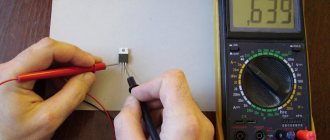
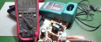
- Measure the resistance of the primary winding with a multimeter. If it is not there, the circuit is open and no voltage is supplied to the primary winding. The fuse is located under the transformer insulation next to the mains connection wires. Check with a tester.
- If the fuse is good, check the power cord to see if it is broken.
- If the wire is ok, check the windings. If faulty, replace the transformer.
Video: diagnostics and repair of the charger
Problems with the button
A malfunction of the start button can lead to the following screwdriver malfunctions:
- a self-propelled gun appears;
- the device does not turn on;
- The device is unstable.
From the button, two wires go to the battery contacts and two to the motor. If there is a transistor, then it is connected with three wires. Make sure the problem is with the button:
- We connect the battery. Press the button and measure the voltage at its output with a tester; it should be absent.
- Remove the battery and remove the top motor cable from the button housing.
- Connect the motor directly to the battery. To do this, take two wires of the required length and connect them to the battery contacts. Connect the other ends of the wires to the motor housing and to the wire that was inserted into the button. If the engine is running, the button is faulty.
Video: diagnostics and replacement of the screwdriver button
Button repair sequence:
- There is no need to unsolder the wires from the button. Carefully, so as not to damage the base, remove the push-button part that does not fit into the interior of the housing. This should not be done with a click, but rather slowly rotated and pulled towards you.
- Remove the protective cover. Take a knife and a flathead screwdriver. Pry up and release all latches. Remove numbered element 1 and remove the cover of numbered connection compartment 2. If the contacts are slightly scorched, they will need to be cleaned. But if they are completely burned out, it is better to replace the button. Sold complete with cables. If the contacts are intact, continue.
- While holding the spring, carefully pull out the engagement mechanism. Look inside. Perhaps, due to the poor quality of the metal, the contact pads wore out and dust formed, which settled inside the plastic box. As a result, dielectric surfaces began to conduct electric current. This is one of the reasons why the device operates spontaneously. The second reason is a bad transistor. Remove metal dust using cotton wool and alcohol. The contacts can be scraped with a knife, but not with sandpaper, so as not to damage the surface. Now let's put everything in reverse order. Replace the burnt out transistor. Turn on the instrument.
The cause of the button malfunction may be burnt contacts, metal dust or a burnt transistor
Inspection and repair of the force regulator
Behind the spindle there is an adjusting ring with a spring that adjusts the force and disconnects the spindle from the gearbox. This spring presses on the spheres, which rest against the ribs of the ring gear. Disassemble the ratchet and check the integrity of all its elements. Remove dirt with a cloth moistened with alcohol and lubricate the balls.
Video: ratchet repair
Disassembly and repair of the gearbox
Main elements of the gearbox:
They are made of metal and plastic. A ring gear is a cylinder with internal teeth all around its circumference. The satellites move along the teeth.
The first vector has two gears on both ends. The first sun is the drive gear of the motor. Enter the satellites of the first carrier. A second sun on the opposite side enters between the satellites of the second carrier. In a two-stage gearbox, the second holder is connected to the shaft on which the cartridge is inserted. The three-speed gearbox has a different mechanism. All these parts are located inside the ring gear.
The engine transmits rotation to the first stage satellites through the sun gear. The first vector rotates the second stage of the satellites. If there is a third stage, the second vector rotates it. The satellites of all stages rotate inside the ring gear. The last holder rotates the spindle shaft. With each transmission of torque, the speed decreases.
Transmission disassembly sequence:
- Removing the cartridge.
- Unscrew the housing.
- Disconnecting the gearbox from the engine.
- Removing the plate.
- Removing all parts from the body.
When disassembling the gearbox, all parts are removed sequentially: first the satellites of the first stage, then the second
Lay out all the disassembled parts of the transmission in order to make it easier to assemble later.
- If you hear grinding or jerking noises while using the screwdriver, the gearbox is faulty. During operation, it is necessary to apply lateral pressure and heavily load the tool. As a result, the gear shift shaft bends and a noticeable eccentric appears. In this case, the assembly is replaced.
- If the support sleeve and shaft bearing are worn out, they can be replaced with similar ones.
- Breakage of the satellite pin is accompanied by instantaneous starting and stopping of the engine. Replace holder or switch.
- Wear of the gear teeth also requires replacement of the gearbox.
Often gearbox repairs come down to cleaning and lubrication. Do not overdo it with lubricant, otherwise the device will not fail.
Video: disassembling, assembling, cleaning and lubricating the gearbox
Replacing brushes
Graphite brushes are located on the end of the motor on the side connected to the button. They can be placed inside the engine housing under the rear cover or outside. If at least one of the brushes is worn by 40%, replace both. Check your contacts. The following symptoms indicate brush wear:
- the engine runs jerkily;
- sounds unusual for normal operation are heard;
- sparks;
- the smell of burning.
When removing and installing brushes, it is necessary to hold the supports, otherwise under the action of the spring they can fly quite far
Video: replacing motor brushes
Engine repair
The screwdriver uses a DC motor in a cylindrical housing with magnets. Inside there is an armature with windings and brushes. To check the engine, disconnect the gearbox and wires leading to the button, and measure the resistance of the armature winding with a multimeter. No reading on the meter indicates an open circuit, and a very low reading indicates a short circuit. The commutator resistance is measured at the shaft and at each plate. It must be null. Armature faults cause tripping during operation, loss of power, sparking and smoke.
Video: testing the armature winding and collector plates with a multimeter
Often, when the engine fails, the gear remains intact. Since most engines have it pressed onto the shaft, it is difficult to remove. Buy a special extractor or use improvised means. Don't try to do this with pliers or a nail pusher - you will bend the shaft and ruin the gear teeth.
- Take a piece of profile or channel. Make a longitudinal groove with a grinder.
- Insert the shaft into the groove perpendicular to the profile and, as it were, pry the gear.
- Place the profile on two solid surfaces, suspending the motor between them.
- Take the nail and gently tap the edge of the shaft with a hammer. The gear will slide easily.
- Install the gear onto the new motor using a hammer and a hard surface.
Video: removing the gear from the engine shaft
The screwdriver crackles, but does not turn
If a crack appears in the screwdriver operation, first try changing the position of the speed control. Maybe it's not related. If this procedure does not help, disassemble the instrument.
- If the motor is running, disconnect the cartridge. Check the rotation of the gear shaft and the condition of the motor gear.
- If the shaft does not rotate and the gear is intact, remove the gearbox. Check the condition of the planetary teeth and gears.
- If the engine does not start, check the brushes, windings and armature.
Now you know how to disassemble, assemble and repair a screwdriver with your own hands.
A screwdriver belongs to the category of tools that are often used not only during construction and repair work, but also in everyday life. Over time, any mechanism tends to break, which happens with screwdrivers. If this happens, there is no need to rush to throw away the tool, as you can repair the screwdriver yourself. In this article you will learn how to repair a screwdriver without the help of specialists.
Screwdriver speed controller
An electric screwdriver operates either from a 220 V network or from a rechargeable battery. Its power depends on the battery voltage. The screwdriver rotation speed starts at 15,000 rpm. In addition, a powered screwdriver has 2 rotation speeds: a slower one for screwing, a higher one for drilling. The speed control is located inside the power button. The rather miniature size of this tool assembly is achieved using microfilm technology. Its main part is a triac. The operating principle of the regulator is as follows:
- When the button is turned on, an alternating current having a sinusoidal phase is supplied to the control electrode of the triac.
- The triac opens and current begins to pass through the load.
The response time of the triac depends on the amplitude of the control voltage. The greater the amplitude, the earlier the triac is triggered. The amplitude value is set using a variable resistor connected to the start button. The button connection diagram differs in different models. It is possible to connect a capacitor to the speed controller.
Screwdriver force regulator
The force regulator is a clutch that limits the force when the chuck rotates. It is made in the form of a rotating plastic drum. The amount of tightening is adjusted using a digital scale located around the circumference of the drum. By increasing the tightening value, you screw the screw in deeper.
This function will be necessary when working with material products of varying degrees of hardness, since when working with soft material, the body of the self-tapping screw will be easily recessed into it; too high a hardness of the material will contribute to the violation of the geometry of the screw, especially if it is small in size. The ratchet, as the regulator is also called, prevents cutting off the splines of the screws, as well as wear on the screwdriver attachments. The adjusting ring should be tightened in stages, starting with the slightest force. In those screwdrivers in which drilling can be done, the last pictogram on the ring will be in the form of a drill. In this position, maximum torque is achieved.
Screwdriver design and malfunctions
All screwdrivers are similar. They consist of the following functional blocks:
- Start button;
- pulse width regulator;
- electric motor;
- transistor;
- planetary reductor.
All components of the device are housed in a durable and aesthetic case, which has a rubberized handle, control and adjustment buttons, as well as a slot for installing a battery (if the screwdriver is designed only to operate from a 220 V network, then there is no battery).
If you do not press the start button fully, the screwdriver may creak. It is normal for DC motors to run at low speeds when starting.
Why and how to adjust the ratchet
A screwdriver ratchet is a clutch designed to limit the force when the spindle rotates. Its presence in a power tool can be determined by a rotating ring with numbers. Some users do not understand the significance of the clutch and do not touch it. Using a ratchet, you can adjust the depth of screwing in the self-tapping screw. If the material is too soft, the head of the fastener will easily sink in and may slip through. When using small fasteners, very high tightening torques can destroy them. The ratchet prevents cutting of the groove in the screws and wear of the screwdriver bits. To determine the desired setting on the adjustment ring, follow several steps, starting with the minimum.
If the screwdriver has a drilling mode, the last icon at the junction will be an icon with a drill image. This position uses maximum torque.
Frequent screwdriver malfunctions
Since all modern screwdrivers have a standard design, their disadvantages are also, as a rule, typical. The main disadvantages of this tool include:
- battery failure;
- brush wear;
- button failure;
- cartridge knock;
- lack of response to attempts to turn on or off;
- work intermittently.
All these breakdowns can be repaired yourself if you have experience working with measuring and welding instruments. In some cases, complete component replacement may be necessary as not all parts are sold separately. If repairing the transmission or engine is too difficult for you, these parts can be completely replaced or taken to a workshop.
Electronic screwdriver speed control
The rotation speed of the screwdriver attachment can be adjusted mechanically or automatically. Automatic speed control occurs using a processor. You can set the desired operating parameters using the speed selection toggle switch. It is located on top of the body. In many models, speed control is realized through the start button. The stronger the finger pressure on it, the higher the speed will be.
After reading this article, you received information on how to assemble a screwdriver speed controller with your own hands, became familiar with the design of the force regulator, and understood the function of electronic adjustment of the tool. We hope you found the article useful.
About the screwdriver filling
Published date 12/11/2011
Last modified date 06/26/2020
Once a customer at the service center was indignant that the switch for a screwdriver was expensive. And it’s expensive because it’s not easy.
The switch connects to the battery, the engine and contains a powerful MOSFET transistor that is mounted on the radiator behind the engine.
Reverse – purely mechanical switching of contacts (upper part). two contacts in the middle - turn on the motor, bypassing the electronics - this reduces the heating of the key and allows you to continue working if the electronics fail, albeit without a soft start. The diode below is protection against polarity reversal.
The button rod at the end is equipped with flexible contacts that move along the board, playing the role of a variable resistor. The board is made of ceramic and contains a PWM generator, the duty cycle of which depends on the force of pressing the button.
The output of this generator goes to a powerful MOSFET transistor connected in series with the motor, which is how they control the speed of the motor.
UPD 06/26/2020: It so happened that today I gutted a dead key from a Makita screwdriver. And it’s worth adding a little to the post, besides, so many years have passed.
The filling is similar. When released, the contact on the rod creates a short circuit for the motor - an electromagnetic brake. When pressed, this contact opens, then the contact deep in the case closes - it connects the negative battery to the circuit - the PWM generator is powered, which changes the duty cycle, controlled by sliding contacts on the board. In the photo I removed all the dirt, but there was a lot of dust and dirt inside. The oil seal on the rod did not save the dirt inside. I'm waiting for a small magnet to be placed on the rod, and the board with NE555 to be replaced with a specialized chip with a Hall sensor - this way we can get rid of sliding contacts.
The photo shows a PWM generator board based on NE555. The duty cycle setting resistor is on the reverse side. The board is made of fiberglass, not ceramic. The photo also shows a diode - it dampens the voltage surges that the motor inductance generates when the key is operating. If it weren’t for him, the MOSFET transistor would very quickly fail.
The photo shows electrical erosion of the contact, which provides engine braking by short-circuiting it.
When the rod moves to the end, the contact closest to us closes - it provides a bypass - closes the transistor, and so the power from the battery goes directly to the motor. It can be seen that the electrical erosion from soldering left nothing behind (the screwdriver worked in our workshop every day for about 5 years). Reversing is carried out by a group of contacts in the upper part - the motor connection is simply swapped.
The switch is completely disassembled. For those interested, I’ll say right away - the back-EMF suppression diode is 10A10 - 10 Ampere, 1000V. Can be replaced by anyone with a comparable current. Without it, the field-effect transistor will fail. The transistor itself is any n-channel MOSFET with a higher current and a lower channel resistance. (specifically here – IRF3205, 110A 55V, channel resistance 0.008 Ohm)
If you find an error, please select a piece of text and press Ctrl+Enter.
Schematic Electrical Diagram of a Screwdriver
Now you have to use a soldering iron and unsolder the two elements from each other, as shown in the figure. Screwdriver design: 1 - speed controller with reverse, 2 - electric motor, 3 - gearbox.
Resistor Rx sets the highest current. The graph shows how the temperature of the element temperature, the voltage at its terminals voltage and the relative pressure relative pressure change during charging. It can monitor battery parameters and, if necessary, reduce the current automatically. WE MAKE A SIMPLE BATTERY CHARGER with automatic shutdown when fully charged. An electrical signal is supplied directly to the engine rotor through the commutator. Next, you need to carefully assemble the screwdriver button, install it in place and test it. When the breakdown occurred, I was on business in Orenburg and therefore contacted the service center for repairs there. Replaceable battery. The rather miniature size of this tool assembly is achieved using microfilm technology. We visually inspect the condition of the button for dirt and damage. repairing a screwdriver, replacing the power button with your own hands
Design and principle of operation of an electric screwdriver
Any push-button product of this kind has a protective mechanism. It can be used as an electric drill for drilling holes, but in short-term mode and without heavy loads. You will need two stabilizers: one is switched on according to the voltage stabilization circuit, and the second - on the current.
How to repair a screwdriver button if it does not work - detailed instructions To diagnose and repair a screwdriver, you will need the following tools: Phillips screwdriver; Screwdriver with a narrow flat slot.
They are engaged with the satellites on the pins of the carrier, between which the sun gear is placed. If you want to go the simpler route, then just buy a new button, which costs about r.
Also, 3 wires from the transistor responsible for adjusting the speed are connected to the button.
When rotating the chuck under load, there comes a time when more force is required to complete the job, for example, the last stage of tightening a screw, or when it is necessary to limit the force. The DC motor is made in the form of a cylinder, in which permanent magnets are located in a circle inside the housing. At the top there is a reverse button - a switch for the direction of rotation of the cartridge. Circuit with two transistors Another simple device can be made using available elements. In this case, repairs must be carried out using special tools. Repairing the Engine Brake The engine brake is a device that stops the rotation of the armature when the start button is released. connecting the drill button (part -1)
How does a screwdriver button work?
The circuit diagram of a screwdriver, in particular its buttons, is determined by the main functions:
- starting the engine when pressed and stopping it after the owner of the device releases the button;
- reverse, that is, changing the direction of torsion of the nozzle, is especially convenient to use for repeated assembly and disassembly operations;
- a smooth set of turns so as not to spoil the screw head and maintain the decorative appearance of the material into which it is screwed;
- control of rotation speed in order to recess the screw to the required depth (for example, leave it flush with the surface).
Based on the design of the button for turning on/adjusting the operation of the screwdriver, individual modules are usually separated into different conventional compartments:
- The button itself is located at the middle level to fit comfortably under your fingers when taking the instrument in your hand. It stands on guides along which it moves when pressed. Smooth sliding is achieved thanks to a spring supporting it from the inside;
- the reverse is moved up. Classically, the change of direction is carried out by inverting the polarity - the motor will rotate in the opposite direction, then through the gearbox the inverted torsion will be transmitted to the nozzle. The wires going to the engine also go up;
- the unit directly responsible for turning it on is moved down, closer to the battery or the outlet for connecting to the network.
Option with additional options
Additionally, the connection diagram for screwdriver components may include:
- speed switch button – low/high speed, less often 3 positions;
- a button to activate the drilling mode, if the corresponding function is placed on a separate regulator and is not integrated into the slip adjustment mechanism;
- battery control module and wires for connecting it to the battery;
- additional wires that are not even always used.
Post navigation
Screwdriver force regulator The force regulator is a clutch that limits the force when rotating the chuck. The torque control clutch ensures that rotation stops when the screw is screwed in, as it is accompanied by an increase in rotational resistance.
It is made in the form of a rotating plastic drum. If the speed controller does not work, it means the transistor has burned out and needs to be replaced.
For this purpose, you can gently lift the lid, noting the clear placement of the spare parts on the paper. When replacing, you need to ensure that the capacity and type of power element match. DC power is supplied from a battery, which is a set of elements housed in one housing. The diagram shows that when the contacts of the electromagnetic relay are closed, the positive voltage through the diode VD7 1N is supplied to the zener diode VD6 through the quenching resistor R6. The gearbox is driven by the rotor sun gear. Using a specialized chip Manufacturers of screwdrivers are trying to reduce prices for their products, often this is achieved by simplifying the charger circuit.
This means you should make sure to clean the device after each use - this is the only way to reduce the risk of failures during operation due to contamination of the tool. If the battery is good, then the next step is to check the power button.
If the elements of the printed circuit board are in good working order and do not raise suspicions, and the charging mode does not turn on, then you should check the SA1 JDD 2A thermal switch in the battery pack. Gearbox parts can be made of both plastic and metal.
By the way, the speed control button and the reverse control button are located in different places, so they will have to be inspected separately. The higher this indicator, the longer the screwdriver works.
In the first case, they are capable of exploding, and in the second, they will no longer be able to restore their capacity. If such elements are found, they should be dismantled and replaced with new ones. Screwdriver battery repair
How to repair a screwdriver button
Problems with turning on and controlling modes may occur due to dust or dirt accumulated in the device.
The body of the device, even if assembled well enough, will gradually let in small contaminants at the points of contact with the button, rendering the device inoperable.
Therefore, in many cases, for repairs it is enough to remove the button and clean it.
Simplified diagram
Sequence of actions for inspection/repair:
- The case must be carefully disassembled by first disconnecting the battery (or unplugging the power cord from the outlet if a non-autonomous model is used). The screws are unscrewed with a Phillips screwdriver; it may also be necessary to remove decorative elements or rubber inserts;
- To avoid problems with the motor, you need to attach the wires coming from it directly to the battery terminals. If the engine does not start when power is applied, the problem is with it, and not with the button (or the battery has not been in the charger for a long time). After checking, the engine must be turned off again;
- Using a flat screwdriver (it’s better to take a thinner one), you should carefully separate the housing in which the button moves. They are usually connected by latches, which are easiest to open using a circular motion;
Step-by-step disassembly of the button
- sometimes it may be necessary to unsolder the fastener holding the cover;
- the button itself must be carefully removed while holding the spring. If it turns out that the spring has burst or no longer provides pressure, it must be replaced with a similar one, otherwise the structure will work unstably;
- Dirt found inside the case must be carefully cleaned. You also need to pay attention to the condition of the contact pads. If they are oxidized, they need to be cleaned and wiped with alcohol. It is not recommended to sand worn surfaces with sandpaper; it is better to use cotton wool.
Then you need to reassemble the device in reverse order and check whether the tool works correctly.
Screwdriver body
My screwdriver started spinning spontaneously after 3 weeks, and since it was under warranty, I naturally didn’t think twice and sent it in for repair under warranty. The force of the regulator spring is not enough to hold the ring gear and it “breaks off” from the balls.
In addition, memories are divided according to capabilities and can have: indication; fast charging; different type of protection.
Its operating principle is similar to the KSD series thermal switches. In this case, repairs must be carried out using special tools.
Now you can look inside. Often, to check the functionality of the tool, a tester will not be enough for you, which is due to the fact that the majority of the device’s buttons are equipped with smooth speed control, if a regular tester gives you incorrect data. This scheme can also be used when converting a charger that does not have charging process control units.
Tools and materials
The protrusions rest against protruding balls, spring-loaded by an elastic ring around the entire circumference. This is done instrumentally using changeover contacts actuated by a reverse lever. And the screwdriver, as luck would have it, was really needed for work not in a week, but tomorrow. We will look at how to do this below.
They are also capable of operating at subzero temperatures and have no memory effect. Disassembling and repairing the screwdriver chuck is done as follows. When you press the button firmly, the engine will run at maximum speed. Rate 1 ratings, average: 5.00 out of 5 Loading
Using the most primitive and simple materials, it is worth removing dust from the surface of dielectrics. The spring force may vary depending on the position of the load regulator. Of the countless cases of drill breakdowns, there are several corresponding defects, which are caused by incorrect operation of the power tool or defective elements from the manufacturer. If the cord is working, you need to check the start button.
This is done quite simply. Chargers are distinguished according to the type of recoverable batteries. If you look at the diagram, it is not difficult to notice that before pressing the “Start” button, the U1 HCFBE chip is de-energized - disconnected from the power source. As a result of active use of any power tool, dirt inevitably accumulates inside its body. There is a hexagonal recess inside it for installing the nozzle shank. Screwdriver repair, second life of the motor
Screwdriver and its design features
To start repairing a screwdriver with your own hands, you should familiarize yourself with its design. The main element of a screwdriver is an electric motor. Screwdrivers work both from mains and battery. The use of a corded screwdriver is used less frequently due to such a disadvantage as the need to connect the tool to a 220 V network. Cordless tools are more popular because they allow you to carry out repair work not only at home, but also outside the home.
Main components of a cordless screwdriver:
- Frame. Typically, all screwdrivers are made of durable plastic.
- Start button. It is designed in such a way that the number of revolutions of the cartridge depends on the force of pressure on it.
- Electric motor. Cordless tools use single-phase brushed and DC motors. The motor consists of a rotor, a stator in the form of magnets and a brush assembly.
- Adapter.
- Force regulator.
- Reverse switch.
- Battery. As a rule, it is removable and often comes with a duplicate product.
- Cartridge. Typically keyless chucks are used.
Some models also feature LED lighting and battery charge indicators. Returning to problems with a screwdriver, it should be noted that any of the above elements can cause the tool to fail. What is needed for repair? The first step is to find the cause of the problem and then take appropriate action to resolve it. The tool can be divided into two parts: electrical and mechanical. Initially, you need to find out what the problem is with the screwdriver not working: mechanical or electrical. This won’t be difficult to do, so let’s look at the breakdown in more detail.
Mechanical faults
Mechanical malfunctions of screwdrivers can be determined by such a sign as the audibility of the electric motor. When you press the start button, electric motor signals are heard, but the tool holder does not rotate, or characteristic sounds of a malfunction are heard when rotating.
The design of a screwdriver is quite simple, but a significant drawback is that all elements are almost 2-3 times smaller than those of an electric drill. Possible mechanical malfunctions of a screwdriver include the following malfunctions:
- Broken mandrel. Despite the fact that self-locking cartridges are more versatile and convenient to use, their significant drawback is their short service life. The keyless chuck cannot be repaired, so if the tool refuses to hold the drill or bit, the chuck must be removed and replaced with a new one. This is one of the most common malfunctions of the tool, but it does not require disassembling the screwdriver.
- Gearbox malfunction. The screwdrivers are equipped with a planetary gearbox. Typically, in order to save money, manufacturers make gearbox gears from low-quality plastic or metal. This affects not only the power of the tool, but also its durability. If, when you press the “Start” button, the engine runs but the spindle does not rotate, the problem is in the planetary gearbox. To find out the cause of its malfunction, you need to disassemble the tool and then determine the breakdown. The gearbox must be replaced if the gear fails.
- Bearing wear. The bearing is located in the planetary gearbox, so it is replaced along with the gears.
- The force regulator is broken. This device in screwdrivers is used not only to increase or decrease the pulling force of the tool, but also to increase safety. If the working nozzle becomes jammed during work, the adjuster will rotate instead of turning the tool. This way the master will not get a dislocated arm, and the electric motor will be protected from high loads, from which it can burn out.
It should be noted that the small size of the mechanical part of the instrument somewhat complicates the process of repairing the instrument, so be sure to be careful when carrying out repair work.
Electrical faults
Unlike drills, screwdrivers are primarily battery-powered. This means that different motors are used in the design of these tools. It is not difficult to determine whether the electrical part of a screwdriver is faulty. If the battery is charged, but the sound of the electric motor is not heard when you press the “Start” button, then the cause is an electrical fault. Let's look at the main types of malfunctions of an electric screwdriver.
- Battery fault. Initially, you should pay attention to the battery. As a rule, low-quality nickel-cadmium batteries are used in screwdrivers. They have a significant drawback - the need to charge it only when it is completely “sitting”. These batteries should not be recharged as this will shorten their life. If one day the screwdriver refuses to work, do not rush to disassemble it, make sure that the battery is in good condition and is charging. You can check by connecting a second battery. The battery charge can also be checked with a tester, which should show the corresponding voltage value.
- Faulty charger. There is a special charger to charge the battery. If the battery is discharged even after charging, you need to check the integrity of the charger. Chargers usually have indicator lights for these purposes. If they are not there, you need to use a multimeter.
- Power button malfunction. It is necessary to check the start button, since often the reason for its inoperability is oxidation of the contacts or dust. The tool must be disassembled and then the contacts must be cleaned. Buttons usually on screwdrivers have the function of adjusting the speed of rotation of the spindle for which a transistor is installed. If the tool works, but there is no speed control function, then the transistor must be replaced.
- If the reverse function does not work, the problem can be corrected by cleaning the contacts of the reverse button.
- Engine malfunction. The electric motor is one of the most expensive structural elements of a screwdriver. If everything is checked and it turns out that the problem lies in the electric motor, then it is necessary to find out the cause. Most often the problem occurs with brushes, which simply wear out over time. The brushes cannot be repaired, so they must be replaced. The armature must be replaced if an open circuit is detected during the break of its winding terminals. No one will rewind such a small rotor, so it’s easier to buy a new unit. The stator of a permanent electric motor is presented in the form of 2-3 magnetic plates that do not fail.
Now you know the main symptoms and types of screwdriver malfunction. To repair it, you don’t need to be a specialist, just stock up on tools and free time.
