Auxiliary tools for CNC machines are equipment that allows for precise and high-quality processing of material. The presence of such devices allows you to increase productivity and production speed. CNC is divided into two types: semi-automatic and automatic. When working with various machines, elements with a certain configuration are used. But without auxiliary tools, the range of functions performed is limited.
The set of parts that make up the most important part of the CNC machine configuration is presented:
- machine tools;
- cutting device;
- auxiliary tool.
Functions
An auxiliary tool is a group of systems, the main function of which is the arrangement of blocks with spare parts responsible for the operation of the unit. The unit is a combination of equipment for cutting and additional tasks.
The most common device of this type is the auxiliary tool for CNC lathes. Thanks to them, they are attached:
- incisors;
- countersinks;
- drill;
- taps;
- scans.
A high-quality auxiliary tool is characterized by a high rigidity index. He must be able to ensure the accuracy and stability of the cutting tool. The device is designed to support all types of work that the machine is capable of performing. The advantage of the device is easy and quick installation. A universal machine must have similar equipment for different modifications. The device can be configured without installing it on the machine.
Examples of work from turning blanks:
These cherry and cedar rolling pins are turned from 53cm long lathes.
Turning blanks in the form of platforms can be used to make bowls and plates. These bowls are made from ash
Candlesticks are a traditional example of products turned on lathes:
For many tools, a round handle is optimal. For example, for turning cutters. Such handles are turned on lathes:
Children's toys, souvenirs and wood figurines can also be made on a lathe:
Honey spindle spoons have a shape that is ideal for turning on a lathe:
It is also convenient to turn various knitting accessories from blanks with a square cross-section - knitting needles, hooks, and so on:
Design
The equipment is secured to the machine thanks to a unified tail section. The fastening is reinforced by elements for connecting to the cutting mechanism. Fastening is carried out manually. The shank of the device has a cylindrical shape and a grooved flat. This design provides a higher level of fastening reliability.
Tooling systems vary depending on what tasks the machine is used for. A quick system change is required when drilling and milling work is carried out. The machine is readjusted by replacing the program carrier. The higher the rigidity of the additional mechanism, the more intense its work will be. The intensity of the work determines how quickly it will be completed.
Rigidity is ensured by durable fastening. To achieve high fastening strength, parts made of hard alloys are used. It is recommended to configure the additional mechanism before installing it on the machine. This will help reduce operating time. Multi-spindle heads simplify the installation of technology on a CNC machine. Such equipment is especially effective for small-scale tasks.
Principles of turning
The technology of metal turning involves the use of special machines and cutting tools (cutters, drills, reamers, etc.), through which a layer of metal of the required size is removed from the part. Turning is performed through a combination of two movements: the main one (rotation of the workpiece fixed in a chuck or faceplate) and the feed movement performed by the tool when processing parts to the specified parameters of their size, shape and surface quality.
Due to the fact that there are many techniques for combining these movements, turning equipment is used to work with parts of various configurations, and also carry out a whole list of other technological operations, which include:
- cutting threads of various types;
- drilling holes, boring them, reaming them, countersinking;
- cutting off part of the workpiece;
- turning grooves of various configurations on the surface of the product.
Main types of metal turning work
Thanks to such a wide functionality of turning equipment, you can do a lot with it. For example, it is used to process products such as:
- nuts;
- shafts of various configurations;
- bushings;
- pulleys;
- rings;
- couplings;
- gear wheels.
Naturally, turning involves obtaining a finished product that meets certain quality standards. In this case, quality means compliance with the requirements for the geometric dimensions and shape of parts, as well as the degree of surface roughness and the accuracy of their relative position.
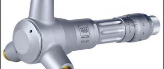
To ensure control over the quality of processing on lathes, measuring instruments are used: at enterprises that produce their products in large series - maximum calibers; for conditions of single and small-scale production - calipers, micrometers, internal gauges and other measuring devices.
Measuring tools often used in turning
The first thing that is considered when learning turning is the technology of metal processing and the principle by which it is carried out. This principle lies in the fact that the tool, cutting its cutting edge into the surface of the product, clamps it. To remove a layer of metal corresponding to the size of such an incision, the tool must overcome the adhesion forces in the metal of the workpiece. As a result of this interaction, the removed layer of metal is formed into chips. The following types of metal shavings are distinguished.
Merged
Such chips are formed when workpieces made of mild steel, copper, tin, lead and their alloys, and polymer materials are processed at high speeds.
Elemental
The formation of such chips occurs when workpieces made of low-viscosity and hard materials are processed at low speed.
Broken shavings
Chips of this type are obtained when processing workpieces made of material characterized by low ductility.
Stepped
The formation of such chips is typical for medium-speed processing of workpieces made of medium-hard steel and parts made of aluminum alloys.
Types of chips during turning
Advantages
The auxiliary tool provides the CNC machine with a number of advantages:
- the time spent on a task is reduced by half;
- the accuracy indicator increases, which ensures material savings;
- stable operation is ensured;
- it becomes possible to service several machines at once;
- there is no need to use devices with a complex design;
- the identical design of the devices allows them to be installed on various machines;
- the equipment can be configured before installation on the machine;
- simplified use of the device;
- the variety of positions for material processing has increased;
- human participation in operating the unit has decreased;
- increased productivity of the machine;
- it became possible to manufacture parts of complex shapes;
- products have become of higher quality;
- equipment productivity has increased;
- using the device has become easier and safer.
Rolled metal retail
Minimum order – from RUB 5,000
From us you can buy rolled steel at retail and in small wholesale. Our warehouse always has a large range of metal in stock: square pipe, round pipe, strip, circle, angle, fittings, channel and other assortment. We cut steel profiles into the required lengths according to your requirements.
buy a metal blank for turning and milling work (sheet) within one or two days by contacting us.
We will promptly deliver your order throughout Moscow and the Moscow region.
Steel circle (bar) GOST 2590-88
Order
No. Name of material Steel grade Price rub/m.l. Up to 1 tonPrice RUR/m.m.
| 3 | Circle 10 | st3, st20, st45 | 29 | 73 |
| 4 | Circle 12 | st3, st20, st45 | 39 | 98 |
| 5 | Circle 14 | st3, st20, st45 | 51 | 128 |
| 6 | Circle 16 | st3, st20, st45 | 67 | 168 |
| 7 | Circle 18 | st3, st20, st45 | 84 | 210 |
| 8 | Circle 20 | st3, st20, st45 | 104 | 260 |
| 9 | Circle 22 | st3, st20, st45 | 126 | 315 |
| 10 | Circle 24 | st3, st20, st45 | 150 | 375 |
| 11 | Circle 25 | st3, st20, st45 | 176 | 440 |
| 12 | Circle 28 | st 3, st20, st45 | 203 | 508 |
| 13 | Circle 30 | st3, st20, st45 | 234 | 585 |
| 14 | Circle 32 | st3, st20, st45 | 303 | 758 |
| 15 | Circle 34 | st3, st20, st45 | 342 | 855 |
| 16 | Circle 36 | st3, st20, st45 | 384 | 960 |
| 17 | Circle 40 | st3, st20, st45 | 474 | 1185 |
| 18 | Circle 50, circle 60, circle 70, circle 80, circle 90 | st3, st20, st45 | Call | |
| 19 | Circle 100, circle 110, circle 120, circle 130, circle 140, circle 150 circle 160, circle 170, circle 180 circle 190 | st3, st20, st45 | Call | |
| 20 | Circle 200, Circle 210, Circle 220, Circle 230, Circle 240, Circle 250 Circle 260, Circle 270, Circle 280 Circle 290 | st3, st20, st45 | Call | |
| 21 | Circle 300, circle 310, circle 320, circle 330, circle 340, circle 350 | st3, st20, st45 | Call |
We have 40X, U10, HVG, aluminum, copper and bronze circles available, call and inquire!
* The price is indicated per linear meter including VAT.
Corrugated steel reinforcement, Reinforcing steel GOST 5781-82
Order
No. Name of material Steel grade Price rub/m.l. Up to 1 tonPrice RUR/m.m.
| 1 | Fittings 8-A3 (corrugated) | А500С | 17 | 43 |
| 2 | Fittings 10-A3 (corrugated) | А500С | 25 | 63 |
| 3 | Fittings 12-A3 (corrugated) | А500С | 34 | 85 |
| 4 | Fittings 14-A3 (corrugated) | А500С | 46 | 115 |
| 5 | Fittings 16-A3 (corrugated) | А500С | 60 | 150 |
| 6 | Fittings 18-A3 (corrugated) | А500С | 75 | 188 |
| 7 | Fittings 20-A3 (corrugated) | А500С | 93 | 233 |
| 8 | Fittings 22-A3 (corrugated) | А500С | 112 | 280 |
| 9 | Fittings 25-A3 (corrugated) | А500С | 145 | 363 |
| 10 | Fittings 28-A3 (corrugated) | А500С | 182 | 455 |
| 11 | Fittings 32-A3 (corrugated) | А500С | 237 | 593 |
| 14 | Fittings 36-A3 (corrugated) | А500С | 300 | 750 |
* The price is indicated per linear meter including VAT.
Square steel pipe GOST 8639-82
Order
No. Name of material Steel grade Price rub/m.l. Up to 1 tonPrice RUR/m.m.
| 1 | Pipe 15*15*1.5 | st 3 | 32 | 80 |
| 2 | Pipe 20*20*1.5 | st 3 | 45 | 113 |
| 3 | Pipe 25*25*2 | st 3 | 73 | 183 |
| 4 | Pipe 30*30*2 | st 3 | 90 | 225 |
| 5 | Pipe 40*20*1.5 | st 3 | 71 | 178 |
| 6 | Pipe 40*40*2 | st 3 | 123 | 308 |
| 7 | Pipe 50*50*2 | st 3 | 147 | 368 |
| 8 | Pipe 60*60*2 | st 3 | 173 | 433 |
| 9 | Pipe 60*60*3 | st 3 | 252 | 630 |
| 10 | Pipe 80*80*3 | st 3 | 353 | 883 |
| 11 | Pipe 100*100*3 | st 3 | 474 | 1185 |
* The price is indicated per linear meter including VAT.
The entire range of pipes available for order: Pipe 15*15*1; Pipe 15*15*1.2; Pipe 20*20*1.2; Pipe 20*20*1.5; Pipe 20*20*2; Pipe 25*25*1.2; Pipe 25*25*1.5; Pipe 25*25*2; Pipe 30*30*1.5; Pipe 30*30*2; Pipe 30*30*3; Pipe 40*40*1.5; Pipe 40*40*2; Pipe 40*40*2.5; Pipe 40*40*3; Pipe 50*50*1.5; Pipe 50*50*2; Pipe 50*50*2.5; Pipe 50*50*3; Pipe 50*50*4; Pipe 60*60*2; Pipe 60*60*2.5; Pipe 60*60*3; Pipe 60*60*3.5; Pipe 60*60*4; Pipe 80*80*3; Pipe 80*80*4; Pipe 80*80*5; Pipe 80*80*6; Pipe 100*100*3; Pipe 100*100*4; Pipe 100*100*5; Pipe 100*100*6; Pipe 100*100*7; Pipe 100*100*8.
Equal-flange steel angle GOST 8509-93
Order
No. Name of material Steel grade Price rub/m.l. Up to 1 tonPrice RUR/m.m.
| 1 | Corner 25*25*3 | st 3 | 61 | 153 |
| 2 | Corner 32*32*3 | st 3 | 79 | 198 |
| 3 | Corner 40*40*4 | st 3 | 124 | 310 |
| 4 | Corner 45*45*5 | st 3 | 167 | 418 |
| 5 | Corner 50*50*5 | st 3 | 187 | 468 |
| 6 | Corner 63*63*5 | st 3 | 239 | 598 |
* The price is indicated per linear meter including VAT.
The entire range of corners available for order: Corner 25*25*3; Corner 32*32*3; Corner 35*35*3; Corner 40*40*4; Corner 45*45*4; Corner 45*45*5; Corner 50*50*4; Corner 50*50*5; Corner 63*63*5; Corner 63*63*6; Corner 70*70*5; Corner 70*70*6; Corner 75*75*5; Corner 75*75*6; Corner 75*75*7; Corner 75*75*8; Corner 80*80*6; Corner 80*80*7; Corner 80*80*8; Corner 90*90*6; Corner 90*90*7; Corner 90*90*8; Corner 100*100*7; Corner 100*100*8; Corner 100*100*10; Corner 100*100*12.
Rolled steel retail
A variety of rolled steel is used both in the construction of houses and in the repair or arrangement of a yard and summer cottage. offers you a variety of rolled steel retail at wholesale prices.
Our prices compare favorably with retail prices on Moscow construction markets. We are ready to ship metal in the required quantity from 1 kg at the best prices.
Rolled steel in stock and on order
We always have in stock in our warehouse:
- Square steel pipes in sizes 15x15, 20x20, 25x25, 30x30, 40x40, 50x50, 60x60 of various thicknesses;
- Equal angles 32, 40, 50 and 63 mm;
- Circle, rod and fittings with a diameter from 8 to 350 mm;
- Strip and wire.
Additional services
To order, we cut metal into pieces of the required length. Pickup from a warehouse in Podolsk. We offer our delivery service in Moscow and the Moscow region. We are ready to perform mechanical processing of the purchased metal (turning, milling, drilling, grinding), welding of products, as well as powder painting.
Setup
Bringing the device into working condition is divided into two parts: adjustment and sub-adjustment. The setup process is the preparation of equipment to perform a work purpose. Pre-adjustment – additional preparation of the unit’s mechanisms. The first part is associated with the main part of the machine that performs the task. The second part represents interaction with technological equipment. It is in the second part that the auxiliary tools are adjusted.
At the first stage of adjustment, the cutting device and its elements are assembled and installed. At the second stage, a pre-configured additional mechanism is installed. At the third stage, the operating mode of the device is selected.
Installation on machines is carried out in three options:
- on the table;
- into the fixture on the table;
- onto the coordinate plate.
The device can be installed on a coordinate plate.
Settings Features
It is recommended to configure the equipment before installing it on the machine. This not only simplifies the setup process, but also saves time. The cutting part of the device has two directions: radial and axial. Installation is carried out in the selected direction at a certain distance from the main part of the device. The optimal distance depends on the unit used.
The most popular machines with auxiliary tools
The auxiliary tool can be used with any model of modern machine tools equipped with CNC. Their popularity depends on demand. The most commonly used types of devices are:
- turning-turret;
- vertical drilling;
- vertical milling.
The device is assembled in accordance with GOST 23597-79. It involves optimal settings for equipment to ensure production accuracy. The accuracy rate is partially adjustable. The level of distortion may vary depending on how professionally the program was installed. The program must take into account the functions provided by additional equipment. Together they can:
- prevent the indicator of distortion of the movement trajectory of the device;
- reduce the feed when using the device;
- adjust the size of the working device.
The design of the auxiliary tool may vary depending on the type of machine it is used for. But the main task remains the same - securing the working elements of the device. Without such equipment, the productivity and period of uninterrupted operation of the device will be significantly lower. The cutting devices will be less secure, which will reduce the quality of manufactured products and the variety of possible shapes.
Devices for processing workpieces on lathes
The nature of installation and securing of the workpiece processed on a lathe depends on the type of machine, the type of surface being machined, the characteristics of the workpiece (the ratio of the length of the workpiece to its diameter), the required processing accuracy and other factors.
When processing on screw-cutting lathes, securing the workpiece in a three-jaw self-centering chuck is widely used (Figure 11a). The cartridge consists of a body 1 with three radial grooves along which cams 2 move. The cams are driven into rotation by a bevel gear mounted in the cartridge body. One of the conical wheels at the end has an end thread (Archimedes spiral). The rotation of the bevel gear is converted into a uniform translational movement of the cams, which move towards or about the center, which ensures that the workpiece is installed along the axis of the chuck and is simultaneously secured by three cams.
| Figure 11 — Devices for securing workpieces on lathes |
Three-jaw chucks are used to secure workpieces with a ratio of their length to diameter.
In relation, the workpiece is installed at centers, and a driving chuck and a clamp are used to transmit torque from the spindle to the workpiece. To install in centers, the workpiece must be centered, i.e. make center holes at its ends. Center holes are made with special center drills; their shape and size are established by GOST. The workpiece with centers is installed in the front and rear centers.
Centers can be support (Fig. 11, b), cut off (Fig. 11, c), ball (Fig. 11, d), reverse (Fig. 11, e) and rotating (Fig. 11, f). The bearing centers are made with carbide tips for increased durability. Cut centers are used when cutting the ends of the workpiece; ball centers - when turning conical surfaces of workpieces by shifting the tailstock in the transverse direction; reverse centers – when processing workpieces of small diameters. In this case, the workpiece is turned to a cone along the edges, and the center holes are made in the opposite center. Rotating centers are used when cutting a layer of metal with a large cross-section or when processing at high cutting speeds.
When installing a workpiece in the centers, a driving chuck (Fig. 11, g) and a clamp (Fig. 11, h) are used to transmit torque from the machine spindle to it. The driving chuck is a housing 3, screwed onto the machine spindle, at the end of which a cylindrical pin 4 is pressed in. The clamp is secured to the workpiece with a bolt.
In relation, the workpiece is set in cents; To transmit torque from the machine spindle to it, a driving chuck and a clamp are used, and to reduce the deformation of the workpiece from cutting forces, steady rests are additionally used. The movable (open) steady (Fig. 11, i) is installed on the longitudinal support of the machine, the stationary (closed) (Fig. 11, j) is fixed on the bed. The cutting forces are absorbed by the steady rest supports, which reduces the deformation of the workpiece.
To process workpieces such as bushings, rings and cups, the following are used: conical mandrels (Fig. 11, l), when the workpiece is held on the mandrel due to the friction force on the mating surfaces; collet mandrels (Fig. 5, m) with expanding elastic elements - collets; elastic mandrels with hydroplastic, corrugated bushings (Fig. 11, n), etc.
On turret lathes, semi-automatic machines and automatic machines, collet chucks are often used to secure workpieces, since these machines process parts whose workpieces are rolled rods.
Parts such as fittings, stepped shafts, flanges, rings, nuts, bolts, etc. are processed on turret lathes. On the machines, external cylindrical surfaces are turned, ends are trimmed, holes are drilled, countersinked and reamed, internal cylindrical surfaces are bored, shaped surfaces are turned, grooves, chamfers, fillets are machined, corrugations are rolled, external (dies) and internal (taps) threads are cut. Conical surfaces are ground with wide cutters or using special copying devices.
| Figure 12 — Schemes for processing a workpiece on a turret lathe: 1 – feeding the rod until it stops; 2 – trimming the right end; 3 – turning two cylindrical surfaces, chamfering and drilling a hole; 4 – countersinking of the hole and turning of the annular groove; 5 - countersinking; 6 – thread cutting; 7 – cutting off the part |
Figure 12 shows the setup of a turret machine for the production of a threaded plug. All surfaces are processed in seven passes.
The surfaces of the workpiece in positions 2,4 (turning a ring groove) and 7 are processed with the feed of a turret caliper, and in positions 3 (turning), 4 (countersinking of a hole), 5 and 6 - with the longitudinal feed of a turret head.
7 Processing of workpieces on boring machines
Boring machines are used mainly for machining holes with precisely coordinated axes in large and medium-sized blanks of body parts.
Processing the surfaces of workpieces with cutters is most typical for boring machines.
Boring cutters operate in less favorable conditions than turning cutters. They have smaller dimensions, depending on the size of the mandrels in which they are fixed and the diameter of the hole being processed. The mandrel with the cutter may bend under the action of the cutting force. The non-rigidity of the tool causes vibrations during the cutting process and reduces the quality of the machined surface. Therefore, to ensure high precision of machined surfaces, boring machines have increased rigidity.
Horizontal boring machines are among the most common; the designs of other universal and special boring machines are based on them.
Boring machines machine holes, external cylindrical and flat surfaces, ledges, grooves, and less often conical holes and cut internal and external threads with cutters. The most common type of processing on boring machines is boring holes.
Boring of cylindrical surfaces.
Boring holes with cutters corrects the shape and axis position of pre-machined or cast holes.
The cutters are fixed in a cantilever or two-support mandrel. The use of a cantilever mandrel is advisable in cases where the length of the hole being machined is l ≤ 5d, since as the length of the mandrel increases, its rigidity decreases, which leads to the need to reduce the cutting depth.
Figure 13a shows a diagram of boring a small-length hole with a two-edged plate cutter mounted in a cantilever mandrel. The workpiece is given a longitudinal feed. With a short hole length, when it is possible to work with a short rigid mandrel, they are bored with axial feed of the axial spindle. Boring with longitudinal feed of the workpiece produces a more correct hole due to the constant overhang of the spindle.
Holes with a l/d ratio >5 and coaxial holes are bored with cutters fixed in a two-support mandrel. When installing it, it is necessary to accurately align the spindle axis with the axis of the rear strut bearing bushing.
Figure 13 — Schemes for surface treatment of workpieces on
horizontal boring machines
Figure 13b shows the simultaneous boring of two coaxial holes. The mandrel with cutters receives the main rotational movement, and the workpiece receives longitudinal feed in the direction from the rear post to the spindle head.
Simultaneous boring of several holes with cutters increases productivity, but does not ensure accuracy, so roughing is usually performed in this way. When finishing boring, to ensure high quality machining, it is recommended to bore each hole separately.
A hole of large diameter but short length is bored with a cutter fixed in the radial support of the faceplate (Fig. 13, c). The faceplate with the cutter is given the main rotational movement, and the table with the workpiece is given the longitudinal feed.
Boring of conical holes.
Conical holes are machined with boring heads mounted in a boring spindle, which is given an axial feed. Conical holes with a diameter of more than 80 mm are bored with a cutter using a universal device mounted on the radial support of the faceplate (Fig. 13, d). During processing, the cutter moves along the inclined guides of the device.
Drilling, countersinking, reaming, counterbore, countersinking and tapping.
On boring machines, these operations are performed in the same way as on vertical drilling machines. The tool is fixed in the boring spindle and the main rotational movement and axial feed are imparted to it. The workpiece placed on the machine table remains motionless.
Grinding of external cylindrical surfaces.
The cutter is fixed on the radial support of the faceplate (Fig. 13, d) and imparts the main rotational movement to it, and the longitudinal feed to the table with the workpiece.
Trimming the ends.
The ends are trimmed in two ways: with the cutter fed in a direction perpendicular or parallel to the spindle axis.
Figure 13, e shows cutting the end with a pass-through cutter mounted on a radial support of the faceplate. The cutter is given a radial feed (in the direction perpendicular to the spindle axis) by moving the faceplate support. Small planes are trimmed with a plate cutter (Fig. 13g), which is given an axial feed (in a direction parallel to the spindle axis) by moving the boring spindle. Radial feed surface machining provides greater precision.
Surface milling.
Figure 13,h shows an example of milling a vertical plane with a face milling head mounted in a boring spindle. The main rotational movement and vertical feed are imparted to the milling cutter by moving the spindle head.
8 Schemes for milling surfaces on horizontal and vertical milling machines
Horizontal planes
milled on horizontal milling machines with cylindrical cutters (Fig. 14, a) and on vertical milling machines
machines - end mills (Fig. 14, b). It is advisable to use cylindrical cutters to process horizontal planes up to 120 mm wide. In this case, the length of the cutter should be slightly greater than the width of the workpiece being processed. In most cases, it is more convenient to process planes with end mills due to the greater rigidity of their mounting in the spindle and smoother operation. This is due to the fact that the number of simultaneously working teeth of an end mill is greater than the number of teeth of a cylindrical cutter.
| Figure 14 — Schemes for processing the surfaces of workpieces on horizontal and vertical milling machines |
Vertical planes
milled on horizontal milling machines with end mills (Fig. 14, f), and on vertical milling machines - with end mills (Fig. 14, d).
Inclined planes and bevels
milled with face (Fig. 14, e) and end (Fig. 14, f) cutters on vertical milling machines, in which the milling head with the spindle rotates in a vertical plane. The bevels are milled on horizontal milling machines with a single-angle cutter (Fig. 14g).
Combined surfaces
milled with a set of cutters (Fig. 14, h) on horizontal milling machines. The accuracy of the relative position of the machined surfaces depends on the rigidity along the length of the mandrel. For this purpose, additional supports are used and the use of disproportionate cutter diameters is avoided (the recommended ratio of cutter diameters is no more than 1.5).
Shoulders and rectangular grooves
milled with disk (Fig. 14,i) and end (Fig. 14,j) cutters on horizontal and vertical milling machines.
It is advisable to mill shoulders and grooves with disc cutters, since they have a larger number of teeth and allow working with high cutting speeds.
Shaped grooves
milled with a shaped disk cutter (Fig. 14, l),
corner grooves
- with single-angle and double-angle (Fig. 14, l) cutters on horizontal milling machines.
Dovetail groove
milled on a vertical milling machine in two passes: a rectangular groove - with an end mill, then the bevels of the groove - with a single-angle end mill (Fig. 14, n).
T-shaped grooves
(Fig. 14, o), which are widely used in mechanical engineering as machine grooves, for example, on milling machine tables, are usually milled in two passes: first, a rectangular profile groove with an end mill, then the lower part of the groove with a T-cutter shaped grooves.