Category: Articles about everything, Articles about radio components, Electrical measurements Published 03/01/2020 · Comments: · Reading time: 3 min · Views: Post Views: 1,229
You can check the resistor value using a resistance measurement (ohmmeter).
A black probe is inserted into the COM connector, and a red one into the VΩ connector. VΩ is a measurement of voltage and resistance.
We switch the multimeter to resistance measurement mode. Diode testing will not help. The continuity test only measures voltage drop, not resistance. We start with a small value of 200 ohms.
One denotes two situations. If the resistor has a resistance higher than the selected limit, the multimeter will show an off-scale value. A unit also means that the device does not see the radio component or there is poor contact between the probes and the part.
A dot on the screen shows the measurement limit. Here the limit selected is 20 kOhm.
The multimeter shows 2.7 kOhm. When taking measurements, you must not touch two metal bases of the probes at the same time. Your body may shunt the part being measured and the parting reading will be false.
A faulty resistor is the most difficult to diagnose. It can be either broken (short circuit) or broken. The problem is that if you don't know the markings or don't have a diagram, it will be more difficult to identify the faulty part.
A broken resistor will be determined by a multimeter as having 0 resistance. And in diode testing mode, the multimeter will start beeping. However, if the actual resistance of the resistor was 1 Ohm, then the device may beep, and in resistance measurement mode it will show errors.
The same thing applies to resistors whose resistance ratings are higher than that of the device being measured. You can also check it using a diode test. If the resistor is working properly, the diode continuity test will not squeak, it will show a voltage drop. But there is a problem here too.
If the resistance is very high, the battery and measuring circuits of the multimeter will not be sufficient for such high values. And the device will show a break.
If you need to check a resistor on a board, it is better to unsolder one contact, otherwise the device will show false values. Other radio components on the board will shunt and introduce their own distortions during measurements.
Main stages of testing
Despite the variety of resistors, conventional elements of this class have a linear current-voltage characteristic, which greatly simplifies the test, reducing it to three stages:
- visual inspection;
- the radio component is tested for breakage;
- Compliance with the nominal value is checked.
If everything is clear with the first and second points, then with the last there are nuances, namely, you need to find out the nominal resistance. Having a schematic diagram, this will not be difficult to do, but the trouble is that modern household appliances are rarely equipped with technical documentation. You can get out of this situation by determining the denomination from the markings. We'll briefly tell you how to do this.
Nominal resistance
The main parameter of any resistor is the resistance value. The uniformity of this resistance is the unit of measurement Ohm. The nominal value of any purchased resistor is marked on itself, that is, on its body using markings in the form of stripes of different colors. This was done primarily for the convenience of conveyor assembly, where machines with machine vision can easily identify the element that needs to be used.
Some resistors are marked with a nominal resistance
Important! You can find out the denomination in several ways: using special reference books and designation tables, as well as any measuring device. The tables are presented in any reference book on electronics and electrical engineering, and are also included with the purchased set of resistors
The second method of determination is more convenient and understandable, since all you need to do is measure the resistance yourself. This will help determine how much the resistance differs from the nominal value and give a characteristic of the element
The tables are presented in any reference book on electronics and electrical engineering, and are also included with the purchased set of resistors. The second method of determination is more convenient and understandable, since all you need to do is measure the resistance yourself. This will help determine how much the resistance differs from the nominal value and give a characteristic of the element.
Checking resistance and serviceability using a digital multimeter
Types of markings
On components produced during the Soviet Union, it was customary to indicate the denomination on the body of the part (see Fig. 1). This option did not require decoding, but if the integrity of the structure was damaged or the paint burned out, problems with text recognition could arise. In such cases, you could always turn to the circuit diagram that supplied all household appliances.
Figure 1. “ULI” resistor, the part rating and tolerance are visible on the body
Troubleshooting algorithm
Visual inspection
Any repair begins with an external inspection of the board
It is necessary to examine all components without instruments and pay special attention to yellowed, blackened parts and components with traces of soot or soot. For external inspection, a magnifying glass or microscope can help you if you are working with dense mounting of SMD components
Torn parts may indicate not only a local problem, but also a problem in the strapping elements of that part. For example, an exploding transistor could drag down a couple of elements in the harness.
An area on a board that turns yellow due to temperature does not always indicate the consequences of part burnout. Sometimes this happens as a result of long-term operation of the device; when checked, all parts may turn out to be intact.
In addition to inspecting external defects and traces of burning, it is worth sniffing to check if there is an unpleasant odor like burnt rubber. If you find a blackened element, you need to check it. It may have one of three malfunctions:
- Break.
- Short circuit.
- Not up to par.
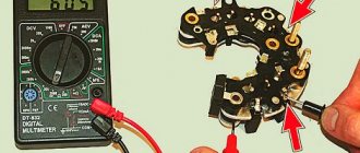
Sometimes a breakdown is so obvious that it can be determined without a multimeter, as in the example in the photo:
Checking the resistor for open circuit
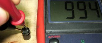
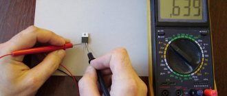
You can check the serviceability using a regular dial tone or a tester in diode testing mode with sound indication (see photo below). It is worth noting that by testing you can only check resistors with a resistance of units of Ohms - tens of kOhms. And not every continuity can handle 100 kOhm.
To check, you just need to connect both probes to the terminals of the resistor, it doesn’t matter whether it’s an SMD component or an output one. A quick check can be carried out without desoldering, after which you can still desolder the suspicious elements and check again for a break
Attention! When checking parts without desoldering them from the printed circuit board, be careful - you may be misled by parallel elements. This is true both when checking without instruments and when checking with a multimeter
Don't be lazy and better unsolder the suspicious part. This way you can only check those resistors where you are sure that nothing is installed parallel to them in the circuit.
Short circuit check
In addition to the break, the resistor could have short-circuited. If you use a dial, it should be low-impedance, for example, on an incandescent lamp. Because high-resistance LED dials “ring” the circuit with a resistance of tens of kOhms without significant changes in the brightness of the glow. Sound indicators cope with this test better than LEDs. By the frequency of beeping one can judge the integrity of the circuit; complex measuring instruments such as a multimeter and ohmmeter are in first place in terms of reliability.
Checking for short circuit is carried out in one way, let's look at the instructions step by step:
- Measure a section of the circuit with an ohmmeter, continuity tester or other device.
- If its resistance tends to zero and continuity indicates a short circuit, unsolder the suspicious element.
- Check the section of the circuit already without the element; if the short circuit is gone, you have found a fault; if not, solder the neighboring ones until it goes away.
- The remaining elements are mounted back, the one after which the short circuit is gone is replaced.
- Check the work results for the presence of short circuits.
Here is a clear example that a burnt resistor has left marks on neighboring resistors; there is a possibility that they are also damaged:
The resistor has turned black from the high temperature, not only traces of burning are visible on the neighboring elements, but also traces of overheated paint, its color has changed, and part of the conductive resistive layer could be damaged.
The video below clearly shows how to check a resistor with a multimeter:
Color designation
Now color marking has been adopted, representing from three to six rings of different colors (see Fig. 2). There is no need to see this as the machinations of enemies, since this method allows you to set the denomination even on a heavily damaged part. And this is a significant factor, given that modern household electrical appliances are not equipped with circuit diagrams.
Rice. 2. Example of color marking
Information on decoding this designation on components is easy to find on the Internet, so it makes no sense to present it within the framework of this article. There are also many calculator programs (including online) that allow you to obtain the necessary information.
Continuity of circuits
To test the functionality of an electrical appliance, it is necessary to test all its connections using the resistance test method. Cable lines are also monitored for integrity using this method. For example, direct connections between connectors or long interface lines. These connections can also be checked with a multimeter in ohmmeter mode. To do this you need:
- Use the knob on the front panel of the meter to set the resistance test mode and the minimum measurement limit (2-20 Ohms);
- Identify the pins of a circuit or cable between which there is a direct connection. This can be seen in the circuit diagram;
- Apply the probes of the measuring device to the selected contacts. If the screen displays a reading in the order of units of Ohms (up to hundreds of Ohms for a cable), then the circuit is operational.
Marking of SMD elements
Surface-mounted components (for example, SMD resistor, diode, capacitor, etc.) began to be marked with numbers, but due to the small size of the parts, this information needed to be encrypted. For resistances, in most cases, a designation of three numbers is accepted, where the first two are the value, and the last is the multiplier (see Fig. 3).
Rice. 3. An example of decoding the value of an SMD resistor
How the device works
According to Ohm's law, resistance is calculated as the voltage across a section of a circuit divided by the amount of current in that circuit. This operating principle is used in the simplest magnetoelectric ohmmeters, which are capable of measuring values from hundreds of ohms to several megaohms. Several methods of measuring resistance are used:
- Magnetoelectric. Direct measurement of current at a known voltage is used.
- Ratiometric. It is based on a comparison of the strengths of two currents, one of which flows through the measured resistor. If the forces are different, the ratiometer shows their difference, which is proportional to the resistance value.
- Analog electronic. Converts the resistance value into a proportional voltage using an op-amp.
- Digital electronic. The measured resistor is installed in one of the arms of the bridge and the value is automatically selected using a digital method.
- Four-wire connection for low resistance measurements. Used to exclude the influence of wire resistivity on the experiment.
Visual inspection
Violation of the normal operating mode causes overheating of the part, therefore, in most cases, the problematic element can be identified by its appearance. This can be either a change in the color of the case or its complete or partial destruction. In such cases, it is necessary to replace the burnt element.
Figure 4. A clear example of how a resistor can burn out
Pay attention to the photo above, the component clearly needs to be replaced, while the neighboring parts “2” and “3” may be working, but they need to be checked.
Resistance Measurement Basics
There are a few simple steps required to measure resistance using an analog multimeter:
- Select the element to be measured: this could be anything where resistance needs to be measured, and estimate what the resistance might be.
- Insert the probes into the required slots. Often a multimeter will have multiple probe sockets. Insert them or check that they are already in the correct sockets. Generally, they may be labeled COM for general, and others where the ohm sign is visible. This is usually combined with a voltage sensing connector.
- Reset the counter: the counter must be reset to zero in order to measure everything correctly. This is done by placing the two sensors tightly together to give a short circuit, and then adjusting the zero control to give a reading of zero resistance (full scale deviation). This process must be repeated if the range changes.
- Take a Measurement: With the multimeter ready to take a measurement, the probes can be placed on the item to be measured. The range can be adjusted if necessary to correct the problem.
- Turn off the multimeter to check its functionality. After measuring the resistance, it is advisable to turn the function switch to the high voltage range. So, if the multimeter is used again for a different type of reading, there will be no damage if it is accidentally used without selecting the correct range and function, but it still needs to be checked.
Checking the variable resistor
The first thing to note is that the meter itself reacts to the current flowing through the component under test. High resistance corresponds to low current and the meter needle deflects more, so it appears on the right side of the dial.
If everything is done correctly, the resistor will ring up easily.
How to ring a resistor to understand whether it is working or faulty.
The basic idea is that the multimeter applies voltage to the two sensors and this will cause current to flow in the element for which the resistance is being measured. By measuring resistance, you can determine the resistance between two probes on a multimeter or other piece of test equipment.
Analog multimeters are good at measuring resistance, although there are a few things to note about how this is done.
Checking for a break
Actions are performed in the following order:
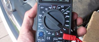
- We turn on the device in the “dialing” mode. In Figure 5 this position is marked as “1”.
Rice. 5. Setting the mode (1) and connecting probes (2 and 3) - We connect the probes to sockets “2” and “3” (see Fig. 5). Despite the fact that in our testing polarity does not matter, it is better to immediately train yourself to connect the probes correctly. Therefore, we connect the red wire (+) to socket “2”, and the black wire (-) to “3”.
If the model of the device you are using differs from the one shown in the figure, read the instructions that came with the multimeter.
- We touch the pins of the problematic element on the board with the probes. If the part “does not ring” (the multimeter will show the number 1, that is, an infinitely large resistance), we can state that the test showed a break in the resistor.
Please note that this testing can be carried out without desoldering the element from the board, but this does not guarantee a 100% result, since the tester can show communication through other components of the circuit.
Preparing a multimeter for measurements: what settings to set
Before measurements, the device is prepared for operation. To do this, it is turned on and the ends of the probes are short-circuited with each other. If zeros appear on the display, then the device is working properly and there is no break in the circuit. The display may show fractions of an Ohm rather than zeros.
Preparing the device for testing
When the probes are open, a working multimeter displays the number 1 and the measurement range. The cable cords are connected in accordance with the mode that you need - “Dialing” or “Measurement”.
How to ring a resistor
The “Continuity” mode (not available in all testers) is used to make sure that there is no short circuit in the circuits running through or parallel to the resistor. To install it, turn the knob towards the diode icon. If there is a current-carrying circuit between the probe installation points, then a sound signal is generated through the speaker.
Dialing mode
This mode is used only for resistors whose value does not exceed 70 Ohms. It makes no sense to use it for parts with a high rating, since the signal is so weak that it may not be heard.
Validation check
If the part is soldered, then this stage will guarantee its functionality. For testing we need to know the denomination. How to identify it by markings was written above.
The algorithm of our actions is as follows:
- We connect the probes as in the previous testing.
- We turn on the resistance measurement (the range is shown in Figure 6) in a mode greater than the nominal value, but as close as possible to it. For example, we need to test a 47 kOhm resistor, therefore, we need to select the “200K” range.
Figure 6. Resistance measurement ranges (marked in red) - We touch the terminals with the probes, take readings and compare them with the nominal value. If they do not match, and this can be guaranteed with a probability close to 100%, do not despair. Both the error of the device and the tolerance of the element itself should be taken into account. A little clarification is necessary here.
What pharmacist malfunctions can you encounter?
You can determine if there is a fault in an element by seeing a distorted image on the screen. This means that the element is highly magnetized. This problem can be resolved by connecting the grid in series with the device. The mesh is the outer loop that covers the inside surface of the screen.
Read also: Checking a car gas cylinder
A posistor is often soldered to the screen. Therefore, it becomes very difficult to check it without disconnecting it from the TV. To take measurements, you need to unsolder at least one part of the device from the grid. But the best solution would be to completely remove the device from the system.
You can heat the posistor with a simple hairdryer. To check the functionality of the device without heating it externally, you need to assemble an electrical circuit. This will help determine the device type. The instructions should state at what voltage the element operates and what temperature it can withstand.
You can determine if the device is working properly by heating it with a hairdryer. If an increase in resistance is noticed, then the element is working. But this method of verification has a drawback - the results may be erroneous. The problem is that the resistance of the parts of the assembled circuit can change over time, and therefore they begin to work unstable.
Another way to determine a posistor malfunction is image distortion. It may ripple, or extra stripes may appear. You can determine the performance of the element using a multimeter. It is recommended that the posistor be cold, since resistance increases when heated.
Another problem is that the contacts have fallen off. With constant heating of the posistor, they begin to wear out, and as a result they fall off. The contacts may look normal on the outside but not work. You can determine their performance using an ohmmeter.
If the posistor is broken or shorted, the fuse will blow the first time you turn on the TV. If there is no short circuit in the network, you need to disconnect the posistor and check its functionality.
What is clearance and how important is it?
This value shows the possible deviation of a given series from the specified nominal value. A correctly calculated circuit must take this indicator into account, or appropriate adjustments are made after assembly. As you understand, our friends from the Celestial Empire do not bother themselves with this, which has a positive effect on the cost of their goods.
The result of such a policy was shown in Figure 4; the part works for some time until the limit of its safety margin is reached.
- We make a decision by comparing the readings of the multimeter with the nominal value; if the discrepancy goes beyond the error limits, the part definitely needs to be replaced.
Cleaning the trimmer with regular alcohol
The resistor in circuits can become dirty; its slider track becomes covered with a layer of dust over time. And in order to return the electrical resistance to its previous performance, you just need to clean it.
Cleaning trimmer resistors is quite simple and quick. It is best to use pure alcohol for these purposes. It is better not to use various products such as nail polish remover, moonshine, or cleaners, as they may contain impurities that negatively affect the cleanliness of the resistor.
To better master the material, we also recommend reading the following material: everything you need to know about stepper motors.
So, we disassemble the resistor (if it has a protective casing), for this it is usually enough to unbend the small metal clips on the resistor body itself, after which you need to remove this cover. Inside the resistor we will see a track along which the slider of the middle terminal of the resistor moves. It is this path that needs to be cleaned from dirt with alcohol.
It’s convenient to do this: take a syringe (let’s say 2 cc), fill it with alcohol, and carefully apply a few drops through the needle of the syringe directly onto the resistor track. After this, we begin to rotate this resistance in different directions so that the alcohol spreads throughout the entire track and thereby clears the way for the slider.
How to clean a resistor at home.
In principle, this is enough so that after assembling and installing the tuning resistor in our circuit workplace, we can enjoy its normal operation without previous problems. Although, if space on the resistor itself allows, you can also carefully go over it with a cotton swab, which will completely remove all dirt from the slider track.
It will be interesting➡ Diode bridge - what is it?
Well, then we need to put our updated resistor back together and put it in our workplace. In most cases, after such cleaning, the electrical resistance is completely restored, and the intermittency of its operation disappears.
Difficult cleaning cases
In very rare cases, it is not a matter of dirt, but, for example, the destruction of this path as a result of excessive overheating. This can happen when too much voltage is accidentally applied to this resistor and the power of this resistor is not large enough to quickly dissipate the generated heat from the high current. This is where the variable resistor track heats up greatly, followed by its destruction. Cleaning with alcohol won't help here.
This resistor needs to be completely replaced with a new one that is known to work. And, of course, before installing a new resistor on the old circuit, check it so that the process of destroying the track does not repeat with a new resistance.
Unfortunately, not all types of variable and trimming resistors can be cleaned using the above method. Sometimes there is resistance in the solid body, which makes it impossible to reach the slider track.
Here you can go to extreme measures. Make a small hole in the body (with a 0.8-1 mm drill). Well, pour alcohol through it with a syringe through a needle. Next, again turn the resistor knob in different directions and then you need to wait until the alcohol has completely evaporated.
You can warm up this variable resistor a little (up to 50 degrees), this will speed up the evaporation of alcohol. Although pure alcohol is a dielectric, it does not conduct current through itself. Consequently, it will not negatively affect the operation of the variable resistor, even if there is some alcohol left on it, which will still evaporate.
How to test a variable resistor?
The principle of operation in this case is not very different; we will describe them using the example of the part shown in Figure 7.
Rice. 7. Trimmer resistor (internal circuit marked with red circle)
The algorithm is as follows:
- We take a measurement between legs “1” and “3” (see Fig. 7) and compare the resulting value with the nominal value.
- We connect the probes to terminals “2” and any of the remaining ones (“1” or “3”, it doesn’t matter).
- We rotate the adjustment knob and observe the readings of the device; they should change in the range from 0 to the value obtained in step 1.
Preparing a multimeter for measurements: what settings to set
Before measurements, the device is prepared for operation. To do this, it is turned on and the ends of the probes are short-circuited with each other. If zeros appear on the display, then the device is working properly and there is no break in the circuit. The display may show fractions of an Ohm rather than zeros.
Preparing the device for testing
When the probes are open, a working multimeter displays the number 1 and the measurement range. The cable cords are connected in accordance with the mode that you need - “Dialing” or “Measurement”.
How to ring a resistor
The “Continuity” mode (not available in all testers) is used to make sure that there is no short circuit in the circuits running through or parallel to the resistor. To install it, turn the knob towards the diode icon. If there is a current-carrying circuit between the probe installation points, then a sound signal is generated through the speaker.
Dialing mode
This mode is used only for resistors whose value does not exceed 70 Ohms. It makes no sense to use it for parts with a high rating, since the signal is so weak that it may not be heard.