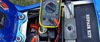
The stable and smooth functioning of the electronic components of the VAZ-2110 largely depends on the performance of the autogenerator. It supplies power to all components of the car and also assists in starting the engine. For this reason, the owner of the car must periodically monitor its performance, and in case of failure, understand how to check the diode bridge of the VAZ-2110 generator with a multimeter.
Testing of the diode bridge (DM) is included in the set of tests for the generator on the VAZ-2110 in case of malfunctions. DM failure is not the only reason for a generator not working. This also includes: voltage regulator, brushes, capacitor, electric stator and rotor windings. All these components can be checked with a regular household multimeter, saving money and time on visiting a car service center.
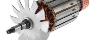
Description of the generator armature
Before checking the unit, please review the basic information. The anchor consists of the following elements:
- shaft;
- slip rings;
- brush assembly;
- collector;
- excitation winding;
- core.
The core of the device includes several sheets made of electrical steel, their thickness should be 0.5 mm. The core is mounted in the shaft, but if the diameter of the armature is very large, then in a cylindrical sleeve. As for the collector, it consists of copper plates, the number of which may vary depending on the design. The collector is assembled separately, after which it is pressed into the shaft using an insulating sleeve.
Generator unit armature device
The winding is made in the form of several sections, their ends are mounted in special protrusions on the collector plates. With the help of the latter, the winding sections are connected to each other in a serial manner, forming a closed circuit. Windings can be wave or loop. In the first, the section leads are connected to the collector unit, and they are connected to each other in a wave-like manner. In loop devices, the leads are connected to the collector plates, and they are connected to each other directly on the collector.
Operating principle
The armature of the generator unit rotates as a result of the influence of the bearing shields, as well as the bearings themselves mounted on the shaft. The shield itself, which is located next to the collector, is called the front shield. Behind this shield, on the shaft, there is an impeller designed to cool the device. To ensure air flow and also remove heat, the shields have special openings that are closed using protective covers with meshes. There are also holes in the front shield, but they are necessary for servicing the component elements of the device.
The armature of the device is connected to the network via a brush assembly. The elements themselves are located on special holders, which are fixed on the so-called fingers. These fingers are located on the traverse, which, in turn, is fixed on the front shield or frame, depending on the design. The pressure of the brush elements can be adjusted; special springs are provided for this.
The number of so-called brush fingers corresponds to the number of poles, and one half of them should have a positive polarity, and the other half should have a negative one. In general, the brush assembly divides the winding into several parallel branches; their number can also vary depending on the type of winding (video author - Volodymyr Zagryvyi / Vladimir Zagryvyi).
The on-board network of the vehicle is connected to the generator unit through a special terminal box, where there is a board with terminal marks on the windings. To ensure lifting or moving the generator unit, there is a corresponding bolt on the top of the frame. On its body there is a plate indicating the manufacturer, as well as basic technical data about the device. One of the main disadvantages of the generator device is the rather large complexity, as well as the too weak strength of the brush assembly, as a result of which the device requires periodic diagnostics and maintenance.
Topic: What goes to the generator exciter wire?
Theme Options
Search by topic
Pointer
Registration 03/25/2011 Address Kaliningrad Messages 92
| Thank you: |
| Received: 0 Sent: 1 |
I measured the blue wire and nothing seemed to be going through it.
Lupo
Registration 06/15/2011 Address Tver Age 36 Messages 230
| Thank you: |
| Received: 5 Sent: 0 |
That's right, the blue wire is needed to excite the generator. When the ignition is turned on, there should be supply voltage. It comes from the dashboard: 12 pin tidy, black 10-pin connector (1 pin) in the ECU box, then to the generator. Look for a cliff.
I confirm
Without this very wire, the gene is excited quite well
But first you need to accelerate.
Pointer
Registration 03/25/2011 Address Kaliningrad Messages 92
| Thank you: |
| Received: 0 Sent: 1 |
Depends on the residual magnetization of the armature and stator.
Well, yes, I agree. I started this recently. And if it stays overnight, he probably won’t get aroused without forced arousal.
Pointer
Registration 03/25/2011 Address Kaliningrad Messages 92
| Thank you: |
| Received: 0 Sent: 1 |
So the problem is in the tidy.
READ How to connect popcorn to computer
Source
Typical faults
Among our compatriots there is an opinion that one of the main faults of the armature is the lack of resistance. It should be noted that the resistance is checked on the rotor winding, and the rotor, in turn, can be installed instead of an inductor, and a stator will stand instead of an armature. This is done in order to provide higher power, so the resistance can only be diagnosed at the rotor.
As for the anchor specifically, it is characterized by the following malfunctions:
- Most often, do-it-yourself repair of the generator armature is carried out as a result of wear on the slip rings;
- also, the need to repair the unit may arise as a result of failure of the shaft bearing;
- not so often, but the problem of winding short circuit still occurs.
We independently check the generator on the “Ten” at home
On any modern car, the generator device performs the important function of powering the battery and all electrical devices while driving. Like any other component, this device can fail over time. In this article we will tell the owners of the “ten” how to properly check the generator on a VAZ 2110 with their own hands.
Self-diagnosis
So we smoothly approached the issue of verification. If you don’t know how to check the functionality of a unit in your car, then first of all carry out a visual diagnosis of the device’s condition. If the check shows that there is no external damage, then a more thorough diagnosis is needed. Initially, you should check the winding for insulation damage; you will need a multimeter or a test lamp to check.
Before checking, one wire from the lamp must be connected to the armature shaft, and the other wires must be touched in turn to the collector plates. Please note that when checking, the wire tips must be reliably insulated. In the event that the armature winding shorts to ground, the light should blink.
To check the turn-to-turn short circuit you will need a special induction device. The core of the device in this case is made of metal, and the coil is powered using industrial alternating voltage. The armature is installed in the prism of the core, after which it must be rotated around its axis, and an iron plate must be connected to the metal. In the absence of short circuits, there will be no current in the winding (the author of the video is the Ramanych channel).
If there is a short circuit, then an electromotive force will be recorded in the closed turns. In this case, the alternating voltage will contribute to the formation of another magnetic field, so if there is one, then vibration will appear in the iron plates connected to the armature. The presence of vibration may indicate that there is a short circuit in the turns; if this is the case, then the only option to solve the problem is to rewind the armature.
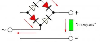
Diode bridge
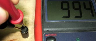
The diode bridge consists of six separate diodes: half of them are positive, the other half are negative. It is necessary to select the “Dial” mode on the multimeter. After this, as soon as the contacts on the tester close, a soft beeping sound will be heard. You need to check in both directions. If a squeak is heard in both cases, then this indicates a breakdown of the diode. Therefore, it needs to be replaced.
Methods for eliminating anchor breakdowns and defects
If the surface of the mechanism shaft is worn out, then the knurling procedure will correct this problem. The mechanism itself is mounted in a lathe, and the worn journals are processed. Their diameter will increase due to the iron that comes out of the formed depressions. When the processing is completed, the harnesses must be sanded so that their dimensions correspond to those that are to be used.
When the collector wears out, its defective elements must also be eliminated. This component is subject to turning, after which the insulation is cut into the plates at a distance of 0.8 mm. In this case, the width of the groove should be no more than 0.6 mm; a milling machine is used to cut through the insulation.
After milling is completed, the armature steel must be treated with a special nitroglyphthalic varnish, and the winding must be treated with insulating varnish. In this case, drying of these elements should be carried out at a temperature of about 110 degrees for 10 hours. Not every service station will provide such conditions for repairs, so it will not be possible to repair the anchor at home.
Selection of diodes for the rectifier bridge
The main thing they look at when choosing a diode is power. It depends on the highest rated current generated by the generator. The higher the generator power, the more powerful the diodes. Diodes for the rectifier bridge are conventionally divided into categories: low power diodes, current 300 mA;
medium power diodes, current 300mA – 10 A;
high power diodes above 10 A.
Diodes are divided according to the type of material used, these are germanium and silicon. Most manufacturers prefer silicon diodes. The main reasons for choosing silicon diodes:
· low reverse current;
· high permissible reverse voltage up to 1500 V;
·operability of silicon diodes from -60 to +150оС
Germanium diodes have a low reverse voltage value of up to 400V. They operate in the temperature range from -60 to +85°C.
For example, to replace diodes for a Bosch generator with a 140A for a Touring Custom car. For such a generator you need 50A diodes, for example, Cargo 50A 138634 and Cargo 138635, for a 140A generator you will need 12 pieces, for an 80A generator 6 pieces.
Video “How to repair an anchor using a lathe”
Visual instructions for repairing the anchor element using special equipment are shown in the video below (video author - Volodymyr Zagryvyi / Vladimir Zagryvyi).
A malfunction of the generator rotor of VAZ 2108, 2109, 21099 (37.3701) cars primarily leads to the disappearance of the charging current and discharge of the battery. On the instrument panel after starting the engine, the battery discharge light will be constantly on, indicating that there is no charging current. The voltmeter needle is in the red zone or on the border with it. If you check with a voltmeter (multimeter, tester, etc.) the voltage at the battery terminals with the engine running, it will be lower than the required 13.6 V.
Tools needed to check the rotor
Multimeter, tester, voltmeter, etc.
If they are not there, then the control lamp is a 1-5 W, 12 V light bulb with wires soldered to it .
Checking the generator rotor of VAZ 2108, 2109, 21099 cars
Checking for short circuits and open circuits can be done without removing the generator from the engine or removing the rotor. We remove the voltage regulator and, through the window that opens, carry out the manipulations described below.
Checking the short circuit of the rotor excitation winding to ground
— We press the plus of the multimeter in ohmmeter mode one by one against the slip rings, and the minus on the generator housing (“ground”).
If the rotor is working properly (there is no short to ground), the resistance should tend to infinity.
When using a test lamp, it is necessary to pass through it, in turn, the plus from the battery to each of the contact rings of the “excitation” winding of the rotor. The minus will be the generator housing, since it is installed on the car and connected to the battery negative. If the rotor is working properly, the control lamp should not light up - plus and minus do not appear anywhere. Otherwise it will burn.
How to properly check the VAZ-2110 generator
One of the most basic spare parts of any car is, of course, an electric generator. As soon as this device fails to function properly, the car lasts no more than 2 hours. That is why it is important not only to repair the generator correctly, but also to diagnose it in time. This article will tell you how to properly check the VAZ-2110 generator.
The following characteristics of the vehicle state indicate that the generator has failed:
- when the engine is running, the battery lamp shows a complete lack of charge;
- during operation, the part constantly overheats;
- the electrolyte inside the battery constantly boils away;
- the headlights begin to dim, the horn makes a quiet (muffled) sound;
- when idling, pressing the gas pedal, the brightness of the headlights increases, and the generator begins to make super-strong revolutions;
- the presence of extraneous sounds (howling, humming, creaking, crackling, and so on);
- the same voltage readings when the car engine is running and when it is turned off.
The VAZ-2110 generator consists of:
- rotor;
- front roof;
- bearing;
- stator;
- slip rings;
- regulator;
- diode bridge;
- back cover.
How to replace the diode bridge of a VAZ-2110 generator
The operation of this type of generator is based on electromagnetic induction by passing a magnetic flux through a copper coil. This is only permissible if electrical voltage passes through the coil.
The voltage source on the VAZ-2110 is the rotor. While moving, it rotates continuously. The rotor consists of a shaft, a pole structure and slip rings.
How to check a VAZ-2110 generator with your own hands
It is very easy to check the operating status of the generator, and you can do it yourself without leaving your home. To check the quality of a part, it is necessary to disassemble it into small parts. In addition, if a segment breaks down, it will be easier to replace it with a single one than to buy a new generator. So, let's look at all the spare parts that need to be disassembled and checked on the generator:
- Pulley. This part should not have any damage or wear on the teeth, otherwise it will jam and the generator will not be able to fully operate. Replacing it is not at all expensive, so if there are any malfunctions, it is better to replace it immediately.
- Bearing. The most important one is the rear bearing. To check its functionality, make several rotational movements, changing the direction of rotation. If scrolling is difficult or unnecessary sounds occur (friction, creaking, etc.), then this spare part must be replaced with a new one.
- Winding. To check this part you will need a multimeter or ohmmeter. Connect the rotor slip rings to the probes of the selected device. During normal operation, the resistance on the device should range from 4.5 to 10.0 ohms. If the resistance has a different value, then the entire rotor must be replaced, along with the armature.
- Transfer the probes of the device to the rotor housing. In good condition, the ohmmeter will show an infinity value, but in a broken state the value will be close to zero.
- With the same device you need to check the quality of the stator winding.
- To check the diode bridge, it is necessary to connect the “plus” probe to the common bus of the rectifier unit, and apply the “minus” probe to the opposite terminals of each diode. Perform the procedure one by one. When changing probes, the resistance readings on the device should differ by several hundred times. Otherwise, it is necessary to replace the entire rectifier unit.
- Carefully inspect the regulator brushes. Most often, they are the reason, so this part needs systematic and regular replacement. Each protruding part must have a length of at least 0.5 cm.
In addition, their movement should be smooth and not interfere with the operation of the preload springs. To check the operation of the regulator itself, you will need a car test lamp. Connect it to the carbon brushes of the regulator, and connect the voltage source to the terminals.
Remember to observe polarity. First, apply a voltage of 13 volts, the lamp should light up. Then gradually increase it. When the voltage reaches 15 volts, the lamp will turn off.
Source: https://ladaprofi.ru/vaz-2110/kak-pravilno-proverit-generator-vaz-2110.html
Signs of generator failure
Signs of abnormal operation of a car generator may include:
- no “battery” indication on the dashboard when the ignition is turned on;
- the “battery” light glows after starting the engine;
- periodic blinking of the “battery” signal indicator while driving;
- the smell of burnt electrical wiring in the generator area;
- failure to start the engine after parking.
Lack of battery charge with a faulty generator leads to problems with starting the engine. More dangerous is a malfunction associated with exceeding the current and voltage of the car battery charge. Many car enthusiasts use a donor battery to start the engine, after which they disconnect the battery terminals to switch to charging their own battery. At this moment, the vehicle's electrical equipment is powered by a generator.
If the generator is faulty, the voltage in the on-board network may be more than 17 volts, which leads to breakdown of the protective zener diodes in the engine control unit. In this case, expensive repairs to the engine control unit are required.
We call the diode bridge
When the multimeter probes are positioned as in the following photos, the resistance should be infinite; if the probes are swapped, it should be within 700 Ohms.
Procedure for checking negative diodes
Checking the positive diodes
Now the auxiliary diodes
Causes and possible consequences of the malfunction
The generator may not work for the following reasons:
- malfunction of the voltage regulator (“pills”, “chocolates” in the slang of car enthusiasts);
- wear (destruction) of brushes;
- short circuit of the exciting winding (rotor);
- breakdown of diodes (located in the horseshoe);
- wear of bearings and bushings.
A faulty voltage regulator usually results in a lack of battery charge. In this case, the “battery” indicator light appears on the dashboard. The engine continues to run until the battery is discharged to approximately 8 - 9 volts.
During daylight hours, the battery charge may be enough for 30-50 kilometers, provided that the battery was well charged at the time the malfunction occurred.
If the output stages of the voltage regulator breakdown, a malfunction may occur due to an increase in the generator output voltage to 17 - 20 Volts. This recharges the battery. The consequence of overcharging is the process of boiling of the electrolyte. If signs of corrosion appear under the hood in the battery area, it is necessary to check the generator.
A breakdown of the diode bridge can occur when the battery is accidentally reversed (installing the terminals in the wrong polarity). Typically, diodes are punched in pairs in one arm. A faulty diode has a resistance close to zero. In this case, the stator winding of the generator operates in short circuit mode and becomes very hot.
After a few minutes of engine operation, the windings overheat, and a smell of burnt electrical wiring appears under the hood of the car. To avoid fire, the engine must be turned off and the generator checked.
Wear of the brushes leads to gradual failure of the generator. First, while driving, the charge indicator light on the dashboard begins to blink, then it begins to glow constantly. In many generator models, the brushes are changed together with the voltage regulator.
Beginning of work
To start checking, no special preparations are required. You just need to prepare the multimeter itself. It is also advisable to check the generator - inspect the generator stator, diode bridge, voltage regulator, etc. This makes it possible to identify faults at an early stage. In addition, an external inspection of other elements of the vehicle's electrical circuit should be carried out. No further work may be required.
So, the verification includes several stages:
- Inspection of the relay regulator.
- Checking the diode bridge.
- Checking the stator.
- Checking the rotor.
Initial check sequence
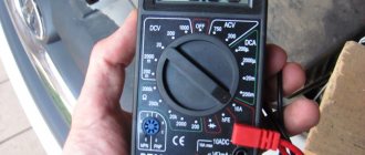
An initial performance check can be performed without dismantling the generator. To do this, set the multimeter switch to the “constant voltage 20V” mode. Next, connect the black probe to the negative terminal of the battery, the red one to the positive terminal. After this, you need to start the engine and let it reach a stable idle speed. Multimeter readings ranging from 13.5 to 14.5 Volts are considered normal.
If the multimeter shows a value less than 12.8 Volts, the charging process either does not occur at all, or the charging current is extremely small. The generator is operating in abnormal mode. When the voltage is more than 14.8 Volts, the battery is overcharged. This can lead to boiling of the electrolyte, an increase in acid concentration, and destruction of the battery plates.
To check the voltage at the generator output, you need to turn on the car lamp in the open circuit from terminal 30 on the generator (the point of contact with the thick wire leading to the positive terminal of the battery or starter).
Next, connect the multimeter in the “=20V” mode with the red probe to contact 30 of the generator, and the black probe to the stripped contact on the engine or body. Start the engine. The reading on the multimeter should not be more than 15.5 volts whenever the accelerator pedal is pressed. Otherwise, further operation of the generator is dangerous for the electrical equipment of the car.
When checking, you should evaluate the degree of tension of the generator belt. Using a simplified method, this can be done by pressing on the belt with your finger.
The amount of deflection should be within 0.5 - 1 centimeter. At the same time, check the degree of belt wear. To determine the reasons for abnormal operation of the generator and perform repair work, dismantling the generator is required.
Relay regulator
The relay regulator maintains the optimal voltage value in the standard electrical circuit. In fact, it is precisely this that prevents the voltage from increasing to critical values. To carry out the test, start the engine, connect the multimeter and set the “voltage measurement” value.
After this, it is necessary to measure the power supply of the on-board network directly at the battery terminals or at the contacts of the generator itself. The values should be between 14–14.2 V.
Then you need to press the accelerator and take the measurement again.
Note! The readings should not change by more than 0.5 V. Otherwise, this will indicate incorrect operation.
Checking generator components
The test begins with monitoring the functionality of the voltage regulator. To do this, the regulator is removed from the generator and a simple electrical circuit is created.
Any car interior light bulb can be used as an incandescent lamp. If voltage regulator 3 is working properly, lamp 6 should not glow at full power. When connected in parallel with the lamp (brushes) of a multimeter, its readings should be from 5.0 to 10.0 Volts. If the multimeter readings fall outside these limits, the regulator must be changed. The design of some generator models allows for the possibility of replacing the regulator without dismantling the device.
Next, check the exciting winding of the generator for breakdown. To do this, set the multimeter to resistance measurement mode at a limit of 200 kiloOhms. The probes are connected: black - to the commutator lamella, red - to the metal part of the armature. The resistance should be more than 100 kiloohms or higher than the upper limit of measurement, as shown in the photo.
The resistance between the lamellas (rotor windings) is usually 0.5 - 2 Ohms.
Checking the stator begins with checking the windings for breakdown. To do this, the red probe of the multimeter is connected to the metal part of the stator, the black probe is connected in series to the windings.
The resistance must be above the upper measurement limit. Then the resistance between the winding contacts is measured. They should differ by no more than 5%. The measurement limit of the multimeter is set to 200 ohms.
If the winding has an electrical breakdown, a short circuit of the turns or a break, it must be replaced. There are workshops that rewind stators and rotors.
To check the health of the diode bridge, the multimeter measurement mode is switched to the “diode” test. Then the diodes (their number on a horseshoe is usually 9) are sequentially “ringed” in forward and reverse connection. In the forward direction (black probe to the cathode) the resistance is 550 - 700 Ohms, when switched in reverse it is greater than the maximum measurement limit.
When the diodes breakdown, the resistance in all directions will be practically zero. This diode should be changed. The difficulty of replacing a diode lies in the fact that the diodes in generators are not soldered, but spot welded to ensure reliable contact at different temperature conditions.
A car generator is an important part of a car's electrical equipment. At the first sign of inoperability, it is necessary to check it using a multimeter.
How to test a generator with a multimeter
What to do if there is no light in the house? A current generator can help solve the problem. But if this equipment also fails, checking the generator with a multimeter will help determine the malfunction. Regardless of the type and brand, with the help of this device, once you find out the cause of the malfunction, you can carry out simple repairs yourself.
There are many types of generators, from large and powerful industrial devices to small automotive devices. But the testing algorithm using the tester is the same for any generator.
What components and parts are checked using a multimeter?
This operation involves diagnosing the electrical part, and checking the following parts:
Voltage measurements are taken at the generator output;
- the rotor excitation winding is checked for open circuit or short circuit to the housing;
- checking the stator windings for breakdown and open circuit;
- carry out fault detection of the diode bridge, capacitor;
- faults in the voltage regulator and brushes are detected;
Performing each of the listed operations requires special knowledge and skill to carry out measurements, so each test should be considered in more detail.
Output voltage level measurement
For each individual unit this value will be different. Let's take a closer look at checking a car generator. Set the voltage measurement mode on the multimeter scale. First you need to check the voltage with the engine turned off. To do this, measure the voltage value at the battery terminals.
We connect the red probe to the positive terminal, and attach the black one to the minus terminal. A charged, serviceable battery will produce a value of up to 12.8 V. We start the engine. Then we take a measurement.
Now this value should be no more than 14.8 V, but no less than 13.5 V. If the voltage level is higher or lower, the generator is faulty.
Checking the rotor winding
To perform this operation, it is necessary to dismantle and disassemble the unit. When performing a self-test, do not forget to set the device to the circuit resistance measurement mode.
Additionally, a value of no higher than 200 Ohm is set. These routine maintenance works are carried out in 2 stages:
- Measuring the resistance value of the rotor windings. To do this, we attach the probes to the rings of the moving part of the engine and determine the value. This will make it possible to determine the probability of a winding circuit break at a value above 5 ohms. If the device shows less than 1.9 ohms, a turn short circuit has occurred. Most often, the chain breaks at the junction of the rotor winding lead to the ring. You can determine the defect by moving the wire with a probe at the soldering points, as well as by detecting darkened and crumbling wire insulation. In the event of a break or short circuit (short circuit), the wires become very hot, so the breakdown can be detected by visual inspection.
- A circuit test is performed to detect a short circuit to the frame. We position the generator rotor conveniently for operation. Then we bring one probe to the rotor shaft, and attach the second to any ring. If the winding is working properly, the resistance reading will go off scale. If it shows low resistance, this part should be sent for rewinding. When rewinding the rotor, it is important to maintain perfect balancing.
Checking the stator windings
Checking the stator begins with a visual inspection. We pay attention to external damage to the housing and insulation, and places where wires are burned during a short circuit.
The faulty unit should be rewound or replaced. If the external integrity of the wires is established, we begin to investigate using a tester.
Before starting work, you should make sure that the unit is disconnected from the network and that there is no contact between the leads of the stator windings.
When performing work to check the normal state of the node, we make sure:
- The integrity of the winding circuit. To do this, set the device to resistance measurement mode. We attach the probes to the first pair of terminals, then check the 1st winding and the 3rd, 3rd and 2nd terminals. If, during a break, the pointer of an analog device goes off the scale, the windings should be rewinded.
- In the absence of an interturn short circuit and to the housing. To do this, connect one of the tips to the terminal, the second to the body. If the windings are short-circuited, the scale will have a lower resistance value than those in good condition.
Voltage Regulator Troubleshooting
Remove and disconnect the wires from the part. We inspect the condition of the brushes. They should not have significant defects or chips. In the guide channels of the brush holder, the generator brushes must move freely. If they protrude beyond the edge by less than 5 mm, the generator regulator should be changed.
The test is carried out using batteries and a 12-volt light bulb. The voltage of the second power source must be at least 15 V, so we connect the batteries in series to the car battery and adjust the value to the desired value. We attach the plus from the 1st power source to the output contact, and the minus to ground.
The light bulb is installed between the brushes. When connecting a 16 V source, it should not light up. With a weaker battery, it lights up. If proper combustion is not observed, the regulator should be replaced.
Checking the diode bridge and capacitor
The purpose of this unit is to prevent the passage of electricity to the generator. It must direct it from the generator to the consumer. In this case, any deviation is a malfunction of the diode bridge.
To check, we dismantle it and solder the terminals on the generator. We set the device to “ring”.
To check the power diode, we bring the black probe to the bridge plate, and attach the red probe to the output. If the multimeter reading is 400-800 Ohm, the diode is working, other numbers require replacing the diode or bridge.
When checking the auxiliary diode, the operation is performed in a similar way. But when the probes are swapped, the device should show a resistance value tending to infinity.
To detect a faulty capacitor, you can check it using the “old-fashioned method”. To do this, you need to apply voltage to it for a short time. It should charge.
When its contacts close, a spark should break between them. This means that the capacitor is working.
When checking a polar capacitor, you need to remove the remaining charge. Then, set the resistance measurement on the scale. The contacts must be attached with correct polarity. When measuring a working part, the resistance gradually increases. Otherwise, when the screen shows 0, it should be replaced.
If a non-polar capacitor is being tested, the value scale is set to MOhm. We place the probes on the contacts regardless of polarity. Then, you need to measure the resistance value. If the number on the screen is less than 2 ohms, this is a faulty part.
In conclusion, it is necessary to recall that all measurements when checking the functionality of the generator using a multimeter are carried out by measuring the value of the electric current resistance.
Only to measure the voltage at the output of the generator, the device is configured to measure this value. Any beginner can test a generator with a multimeter. You just need to work with full responsibility and follow the instructions.
Source: https://EvoSnab.ru/instrument/test/proverka-generatora-multimetrom
Design features of the generator
Structurally, all generators installed on cars consist of a rotor, stator, covers cast from aluminum alloy, voltage regulator, rectifier unit (diode bridge) and brush assembly.
The rotor is a shaft on which the excitation winding is installed between two pole halves - magnetic cores. There are six beak-shaped protrusions on each half of the magnetic circuit. As the rotor rotates, the beaks of the magnetic circuit alternately cross the magnetic field of the stator, inducing a current in the winding.
When voltage is applied to the rotor of the brush generator, the beaks directed towards each other are magnetized. One half is magnetized in the “south” direction, the other in the “north” direction, and when the rotor rotates, the magnetic field changes cyclically from “north” to “south”, exciting an electric current. In a generator that does not have a brush assembly in its design, the beaks of the magnetic circuit are magnetized in a similar way, and at the same time have their own rotation. In practice, such generators have not found widespread use due to their unreliability, complicated design, large dimensions and weight, as well as frequent breakdown of magnetic circuits, leading to the destruction of the entire generator.
