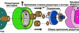
The exact technical definition of a gearbox is a device for converting mechanical energy in terms of parameters. It has characteristics of input and output indicators. In practice, the gearbox can not only change the kinetic parameters and levels of energy transfer, but also change the direction of rotation and following of the shafts.
Today, a gearbox is considered in terms of a device that is used to change the shaft rotation speed relative to the drive mechanism. At the same time, the possibility of increasing torque or ensuring an extremely low number of revolutions with very serious efforts can be considered. By design, gearboxes are divided into:
- cylindrical;
- conical and conical-cylindrical;
- worm;
- planetary;
- combined, in which several conversion schemes are used simultaneously.
To understand how suitable a particular type of gearbox is for solving the tasks assigned to it, it is worthwhile to dwell in detail on the features of their operation and conditions of use.
Helical gearbox: general information
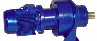
The helical gearbox is the most common type of converter mechanism. It has the main characteristic: the input and output shafts are strictly parallel, but not necessarily coaxial.
The advantages of a helical gearbox include:
- high efficiency, energy losses are minimal;
- does not have self-braking, it is always possible to rotate the output shaft even with little force;
- can transport high power;
- has kinematic accuracy;
- practically do not heat up, without requiring special cooling conditions;
- Products are produced with different gear ratios and conversion stages.
Due to the presence of a large range of products on the market, it is not difficult to select a spur gearbox with the desired gear ratio for use in a particular mechanism.
Using different types of systems
The use of a gearbox, which is the main element of the vast majority of complex units and devices, is observed in almost all areas of industry.
In cars, the system is present in the gearbox, regulators, gasoline pump, driveshaft, and brake system. In heavy industry, work tools contain worm and cylindrical models. Gas reducers are the main element of the processing and gas production industry. Geared motors are a key element of almost all household appliances.
It will not be difficult to buy a general industrial gearbox from the manufacturer, of any type, if you contact specialists. We present all types of described systems, so each client will be able to choose a model that fully meets his requirements.
The material for this article was taken from the site https://promreduktor.com.
How does a helical gearbox work and where is it used?
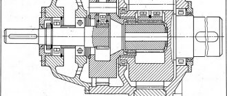
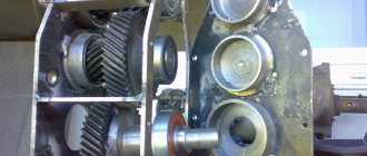
The basis of the design of a helical gearbox is gear wheels in the shape of cylinders. The coaxiality (location of the axes of machine parts (assemblies, assemblies, etc.) on the same line) of the input and output shafts depends on the number of transmission stages. In the simplest version, there are only two spur gears inside the housing. In this case, the displacement of the output shaft from the input shaft axis is determined as the sum of the radii of the wheels along the outer contour minus the depth of the teeth.
The alignment of the input and output shafts is achieved by using several conversion stages. In this case, an odd number of cylindrical gears are located inside the housing, some of which are auxiliary. They can serve as a simple transmission mechanism without conversion, or have a gear ratio to reduce the load on the teeth and increase the service life of the mechanism.
Helical gearboxes are produced in closed housings; most of them do not require special maintenance. The scope of application of these devices is extremely wide. They guarantee smooth transmission, but do not allow changing the direction of the shaft.
Helical gearboxes can be located vertically or horizontally; calculation of load and speed is simple: high efficiency allows the use of the gear ratio specified by the manufacturer in arithmetic operations. The main advantage of the gearbox is the conversion of drive energy with virtually no distortion or loss.
Specifications
Gearboxes differ in appearance in size and shape. The internal structure is varied. What unites them all is a list of technical characteristics by which they are selected for various machines and machines. The main parameters of the gearbox include:
- gear ratio;
- gear ratio;
- gearbox torque value;
- location;
- number of steps;
- torque.
The gear ratio is taken as the total of all gears, and at the same time a table of gear ratios is indicated if the unit has 2 or more stages. Using it, a unit is selected that converts the rotation of an electric motor or motor with the required number of revolutions.
In this case, it is important to know the amount of torque on the output shaft of the gearbox in order to determine whether the power will be sufficient to drive the unit.
Gear ratio
The main characteristic of gearing, by which all other parameters are determined. Shows how many fewer revolutions the wheel makes relative to the gear. Gear ratio formula:
U = Z2/Z1;
where U is the gear ratio;
Z1 number of gear teeth;
Z2 is the number of gear teeth.
The module of the gear and wheel teeth is the same. Their number directly depends on the diameter. Therefore, you can use the formula:
U = D2/D1;
Where D2 and D1 are the diameters of the wheel and gear, respectively.
The calculation of the total transmission torque is determined as the product of the gear ratios of all pairs:
Uр = U1× U2× … × Un;
Where Ur is the gear ratio;
U1, U2, Un gear ratios of gear pairs.
When calculating the gear ratio, the ratio of the number of wheel teeth and worm engagements is taken.
In chain drives, the calculation of the gear ratio is done in a similar way, based on the number of teeth on the sprockets and the diameters of the parts.
When determining the gear ratio of a belt pair, the number of teeth is replaced by the diameters of the pulleys and everything is multiplied by the slip coefficient. Unlike a gear train, the linear speed of movement of the extreme points on the pulleys is not equal to each other. The engagement is not rigid, the belt slips. The transmission efficiency is lower than that of gear and chain transmission.
Gear ratio
When designing a new unit with predetermined characteristics, the power of the future gearbox is taken as a basis. It is determined by the magnitude of the torque:
where U12 is the gear ratio;
W1 and W2 – angular velocities;
n1 and n2 – rotation speed.
The “–” sign indicates the opposite direction of rotation of the wheel and the shaft on which it is located. With an odd number of gears, the driven wheel rotates in the opposite direction to the driving one, towards it. With an even number of bevel gear engagements, both shafts rotate in the same direction. You can make it spin in the desired direction by installing an intermediate part - a parasite. It has the same number of teeth as a gear. The parasite only changes the direction of rotation. All other characteristics remain the same.
Torque
Determining the torque on the shaft is necessary; it allows you to find out the power at the output of the gearbox; the quantities are directly proportional.
The input motor torque at the input is multiplied by the gear ratio. To obtain a more accurate actual value, it must be multiplied by the efficiency value. The coefficient depends on the number of steps and the type of gearing. For a spur bevel pair it is 98%.
Features of bevel and bevel-helical gearboxes
The operation of bevel and bevel-helical gearboxes has the same features and basic characteristics as cylindrical devices. The main difference is in the shape of the gears inside the housing.
As the name suggests, a bevel gearbox has all gears of a conical shape; a bevel-cylindrical gearbox has elements of both types in its design.
Gearboxes of these classes have their own characteristics:
- capable of changing the direction of the shafts, a bevel gearbox with one conversion stage provides a rotation of 90 degrees;
- the force during gear operation is directed at an angle to the shaft axis. Therefore, bevel and bevel-helical gearboxes must be secured separately to avoid lateral pressure on the drive axis. This may somewhat complicate the design of mechanisms with their participation.
The types of gearboxes under consideration are used only in cases where it is impossible to do without changing the direction of the shaft. These devices are expensive, which is easily explained by the increased complexity of manufacturing gears and the need to guarantee the accuracy of the assembly of the gearbox as a whole.
But otherwise, the devices operate almost silently, products are offered with different gear ratios, they do not require special maintenance, and their service life is very long. The rules for calculating the output shaft speed and torque are the same as for helical gearboxes.
What difficulties might you encounter?
Most often, the weak point of an automobile gearbox is the working components, that is, those that are subject to significant wear. The main reason is increased stress and prolonged oil starvation. The last factor is associated with a deficiency or complete absence of transmission fluid.
A gearbox failure in a car is indicated by an unpleasant sound, hum, vibration and clicking in the units where the gears and bearings communicate. If the oil seals fail, transmission fluid leaks and regularly seeps through the cracks that have formed.
gearbox in car breakdown
Damage to the housing with broken fasteners is an infrequent, but very dangerous occurrence. It occurs as a result of a vehicle hitting some high or sharp obstacle. In 70% of cases, after such an incident, a crack or group of cracks forms at the place where the housing is attached. They won’t cause any problems right away, but later dirt and dust get into them, damaging the structure of the transmission fluid.
Subsequently, the raw material cannot perform the previously assigned functions of cooling and lubrication of gears. This leads to overheating, wear and even breakage of the teeth. If the car gear housing has been damaged, this may be indicated by a loud hum from the operating elements. This has a noticeable effect on acoustics and ride comfort. Oil leaks occur in places where the housing or its fastenings are damaged.
Worm gearboxes: general information
The mechanics of a worm gearbox is based on the idea of transmitting torque from a specially threaded screw to a gear wheel.
In this case, during the operation of the mechanism, significant friction forces are formed between the surfaces of the worm and the tooth of the shaft drive mechanism.
As a result, the device generates a large amount of heat, requires special cooling conditions, and has a low mean time between failures.
Over time, due to the destruction of drive elements, backlash and increased heat generation may occur.
The advantages of a worm gearbox include:
- smooth running of the output shaft;
- large transfer coefficients;
- To perform the tasks assigned to some mechanisms, the self-braking property of the gearbox is useful: the shaft cannot be rotated when the drive is turned off.
The worm gearbox has a significant list of disadvantages. In addition to those already mentioned (significant heat generation, low service life), these include:
- reduced efficiency, which drops during operation due to wear and tear of the mechanics;
- Fine adjustment and tuning is required.
The worm gearbox requires separate mounting during installation to ensure that there are no parasitic multidirectional forces acting on the output and input shafts. If this condition is not met, the service life of the device may be reduced compared to that declared by the manufacturer.
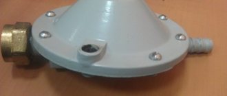
Execution options
Now let's talk about the options for their execution, considering different manufacturers of pressure reducers, it can be noted that each manufacturer has its own features and useful features that definitely need to be taken into account when purchasing them. Before this, we looked at two types of pressure reducers that have a classic design, and for example, another manufacturer, well known to many, offers you to get both a reducer and a filter in one bottle, so to speak.
And if you consider that some gearbox manufacturers directly indicate that it is necessary to install a strainer in front of the gearbox, then here you immediately get two devices in one.
I won’t argue, of course, and the price of such a device is quite high, and many will probably say: for this money you can buy two simple membrane reducers and two wash filters, but as they say, this depends on the taste and color.
But, for example, in cramped conditions where the input unit is located, reducing space and installing a two-in-one device may even be very justified. Options for the design of a gearbox with a flushing filter can be different, for example, the filter flask can be transparent made of plastic, or it can be a closed type.
It’s difficult to say which is better, someone probably wants to see how much dirt has collected in the filter housing, but the truth is that with bad water, after some time the transparent flask will probably no longer be so transparent. When choosing a reducer, you must definitely look at its characteristics; products with a transparent flask, as a rule, are used only for cold ones and often, according to their characteristics, can withstand less pressure compared to a similar one that has an already closed flask. There is a gearbox with a built-in standard oblique filter that protects its mechanism. The pressure reducer can have a hole for a pressure gauge, which is definitely very convenient, since there is no need to install an additional unit with a pressure gauge. Thanks to the pressure gauge, you can control and set the required pressure at the outlet of the device. Now about the adjustment, the classic version of the gearbox involves adjusting the water pressure using a pressure gauge, where the adjustment itself is made by turning a key or screwdriver inserted into the adjusting sleeve of the gearbox, rotating the sleeve to the required reading on the pressure gauge.
This method, in principle, is not burdensome, does not require much time and is quite simple. But some manufacturers went even further and presented the buyer with a gearbox with the ability to adjust the pressure by hand, guided by the digital divisions of a scale located directly on the gearbox body.
This option is definitely convenient, but as they say, you have to pay for everything, in any case, to be 100% sure, it is much more correct to control the pressure using a pressure gauge, comparing it with the digital scale indicated on the gearbox.
Where are worm gearboxes used?
Worm gearboxes are most often used in mechanisms that require the transmission of low power with a large conversion ratio. For example, devices with weak high-speed engines that provide a small number of strokes or revolutions of the executive body.
Many mechanisms may require a low angular speed of rotation of the output shaft. In this case, a worm gearbox will be ideal. It guarantees significant output torque, and thanks to the huge gear ratio, the output speed is very low. These can be gate drives, various lifts of a lever design.
To solve some problems, a feature of worm gearboxes may be useful, which consists of changing the direction of the output shaft relative to the input shaft by 90 degrees. This indicator never changes.
Separately, it is worth noting the combined gear reducers. They carry out a double conversion: preliminary using a cylindrical circuit and final - using a worm gear. This achieves an even higher conversion factor for the lowest angular velocity of the output shaft.
Gearboxes
This group of components differs in the principle of connecting the teeth of the drive and driven gears. Thanks to the use of various variations, four groups of gearboxes in cars are distinguished:
- Bevel - two bevel gears are located perpendicular to each other. This scheme is used in rear- and all-wheel drive vehicles.
- Spur gear - two cylindrical gears communicate with each other in parallel. This circuit is used in front wheel drive cars.
- Hypoid - gears are located at an angle of 45 degrees relative to each other. This scheme is used in rear-wheel drive and all-wheel drive vehicles.
- Worm - one screw communicating with a worm driven gear.
Planetary gearbox: general information
The design of the planetary gearbox allows it to operate in two modes: as a rigid converter of mechanical energy and as a model of a summing mechanism that selects torque from two drives. The advantages of a planetary gearbox include:
- compactness;
- universality of application of output torque, both for driving shafts and for transmitting rotation to gears;
- light weight;
- high efficiency.
The disadvantage of a planetary gearbox is its high cost. This is due to both the large number of parts in the conversion mechanism and the requirements for high precision in their manufacture.
How does a planetary gearbox work?
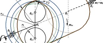
The transmission of rotation in a planetary gearbox is carried out from the gear, which the drive rotates, to the outer circular element - the epicycle. The conversion factor depends on the ratio of the number of teeth on the sun gear and planetary gears.
The gearbox diagram is shown in the figure:
When the carrier, indicated in green, is rigidly fixed, the planetary gearbox works as a simple converter of the mechanical energy of one drive. The second use case is to rotate the sun gear and carrier from different sources. In this case, the energy is summed up, and the calculation of the final power on the epicycle is quite complicated.
Design, principle of operation and purpose of an angle grinder
The source of torque for grinder tools is a commutator electric motor . The final working value of the torque on the working attachment is achieved using a gearbox, the design of which is compact to ensure the minimum dimensions of the entire power tool, which is an important parameter for manual use of the device.
Scheme of operation of the grinder. Source
From the technical name of an angle grinder, its main purpose follows - grinding the surfaces of processed materials. However, the versatility and versatility of grinders allows, with the help of replaceable attachments, to perform such technological operations as cutting, stripping, polishing and some others.
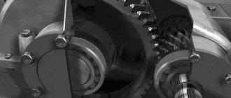
How the gearbox works, sectional view, photos and drawings
The minimum dimensions of the gearbox are ensured by the use of bevel gears . The small bevel gear meshes with the large one, and the direction of rotation of the electric motor rotor shaft changes by 90°, thereby reducing the size of the angle grinder in length. The driven gear, narrow in thickness, allows the design of the gearbox housing to be made as flat as possible, which ensures the operation of the grinder in hard-to-reach places .
Grinder gearbox in section. Photo source
.
The supporting units of the rotor and spindle shafts are made using ball bearings, needle bearings and bushings made of antifriction materials, depending on the model of the angle grinder, capable of withstanding large axial loads. The housing in which the shafts of the driven and driving gears are assembled and the bearing units are reliably protected from dust that is generated when working with an angle grinder. An example of a gearbox design is shown in the image. How to disassemble for the purpose of diagnostics and repairs can be found in a separate article.
Adjustment
The angle grinder's bevel gear will work without problems with shafts rotating freely in bearings that have no backlash. This is achieved by installing additional metal spacers on the drive and driven shafts to eliminate gaps formed during the assembly process.
A feature of the bevel gear is the adjustment of the gear itself . It is necessary to ensure alignment of the initial cones of the gears. Here you should also take into account the presence of a thermal gap , which prevents the transmission from jamming when heated during operation. metal gaskets are installed between the housing and the gearbox cover . The correct adjustment is monitored by the contact patch. In practice, this is done by applying a coloring substance, for example, blue, on the surface of the teeth and after running in the operating mode, the area of the working surface of the tooth on which there is no blue is visually determined. The correct location and size of the contact patch is shown in the image below.
Depending on the degree of transmission accuracy there should be:
a = (0.4 – 0.8)b;
hav. = (0.6 – 0.9)h.
In grinders, metal spacers are installed between the cover and the gear housing, the number of which corresponds to the correct initial adjustment of the gearing. As the teeth wear out, to maintain the gap and normal operation of the transmission, some of the gaskets are removed, thereby ensuring the life of the grinder gearbox.
Gear ratio (ratio)
Angle grinder (grinder) MAKITA GA9010C. Photo 220Volt
In the classical sense, the gear ratio of an angle grinder gearbox, like any other mechanical gearbox, is the ratio of the revolutions of the drive shaft to the revolutions of the driven shaft . For most angle grinders it ranges from 2.5 to 4 . The gearbox is a reduction gearbox in order to provide speeds at which rapid overheating of the treated surface does not occur and the torque required for operation is achieved.
To a greater extent, the gear ratio of grinder gearboxes depends not on the manufacturer’s model, but on the power of the grinder. Less powerful angle grinders have higher spindle speeds and, accordingly, a lower gear ratio. For powerful professional angle grinders, high torque is important and high spindle speeds are not used when working with large diameter nozzles to ensure safety. Here the gear ratios are closer to the maximum values.
Where is the planetary gearbox used?
Due to its small size and smooth running, planetary gearboxes are recommended for precision mechanisms. A wide range of products are offered on the mass market. Gearboxes are available with different conversion ratios that can transmit more power by reducing the angular velocity of the output device. This can be extremely useful in metalworking machines.
Planetary gearboxes show good results in various lifts and conveyors. They are able to provide a smooth change in power with minor load surges on the drive. To ensure high power of conveyors, additional drives with planetary gearboxes in summation mode can be used, which can ensure the creation of long, highly loaded conveyors or lifts.
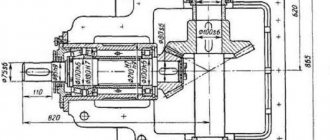
Description of design
Worm gearboxes are one of the most common types of gearboxes. A worm gear is the engagement of a worm with a worm wheel. A worm is a screw with a thread cut on it, the profile is close to trapezoidal. Worm wheel is a helical gear with a special tooth profile. When the worm rotates, the threads move along its axis and push the teeth of the worm wheel in this direction. The axis of the worm crosses at right angles with the axis of the worm wheel, the distance between them determines the size of the gearbox. In Russian-made gearboxes, this size is an integral part of the gearbox designation and determines its overall size. For example, Ch-80 is a single-stage worm gearbox with an interaxial distance of 80 mm, and Ch-100, accordingly, has an interaxial distance of 100 mm.