Design features
There are two types of bevel gearboxes:
- narrow;
- wide.
The narrow type of gearbox means that the width of the gear will be equal to a quarter of the outer cone distance. Gear ratios are in the range of 3-5, and the number of teeth on the gear is 20-23. For wide-type gearboxes, the wheel width varies from 0.3 to 0.4 outer cone distance. The gear ratios will be 1-2.5, and the number of gear teeth will be from 25 to 28.
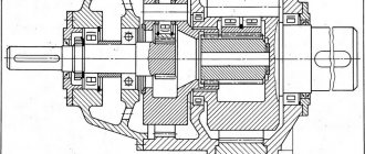
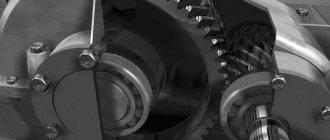
The figure below shows a drawing of a bevel gearbox, which shows that the gears contact at a certain angle. The shafts are mounted on single-row roller bearings and are located in a closed housing with a cover. In most cases, the material for the body is steel or cast iron, but there are models made of light alloys. The design uses bevel-type gears with straight or oblique teeth. The use of radial bearings allows them to withstand large axial loads.
According to the type of design, bevel gearboxes can contain one or several stages, with an increase in which a larger number of shafts and bevel pairs will be used. The most common today are single-stage bevel gearboxes. Thanks to two-stage and three-stage units, it is possible to achieve the required torque and reverse movement.
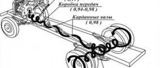
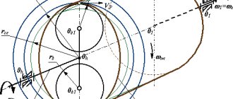
Regardless of the number of stages, rotation is transmitted to the gearbox from the electric motor using a clutch, V-belt or chain drive. The figure below shows the kinematic diagram of a single-stage gearbox.
The conical pair is lubricated using an oil bath. One of the gears is partially immersed in oil and, when rotated, moves some of the oil to the other gear, from which oil drips back into the bath. During operation of the unit, some of the oil gets onto the inner walls of the housing, in which there are technological holes. Through them, oil reaches the bearings and lubricates them.
Design No. 3
The gearbox is a single-stage bevel gearbox with angles between the shaft axes not equal to 90º . The gearbox has limited use. When the load capacity of the engagement is high and the high-speed shaft rotates at a significant speed, the design of the bearing unit, version II, is used. Roller bearings with short cylindrical rollers carry radial load, and a radial ball bearing installed in a cup with a gap carries axial load.
In the bearing unit of version III, tapered bearings are installed “extended”. When assembling a bevel gear, the bearings are first adjusted by axial movement of the inner bearing ring using a round nut, and then the engagement by moving the gear shaft in the axial direction by changing the thickness of a set of thin metal spacers between the housing and the cup flange.
1.Classification of gearboxes
Reducer for general machine-building purposes. This type of equipment is an independent unit used in machine drives. Its technical characteristics meet common requirements for different applications. Structurally, general machine-building gearboxes may differ.
Special gearboxes are designed for automotive, aviation and other highly specialized industries. From the name it is clear that the units of this group must correspond to the specifics and parameters of a particular application.
Gearboxes can be classified according to the following criteria:
- By type of gear and number of stages;
- According to the location of the axes of the input/output shafts in space and relative to each other;
- According to the method of fastening.
Bevel gearboxes
A gearbox (bevel) is a mechanism that converts a high angular speed of rotation of the input shaft into a low one on the output shaft. In this case, the torque on the output shaft increases in proportion to the decrease in rotation speed.
The gearbox (bevel) consists of a housing in which gears, shafts, shaft bearings, their lubrication systems, etc. are located. The presence of the housing ensures safety, good lubrication and, therefore, high efficiency, in comparison, for example, with open gears.
Main characteristics of gearboxes
Main characteristics of gearboxes: gear ratio, rotation speed of input and output shafts, gear ratio, transmitted power, number of stages and type of gears.
The gear ratio is the ratio of the rotation speed of the input shaft to the rotation speed of the output shaft.
i = win/wout
The efficiency of the gearbox is determined by the ratio of the power on the input shaft to the power on the output shaft
n = Pin/Pout
Description and principle of operation:
Bevel gearboxes are very close to spur gearboxes, but have one fundamental difference - bevel gears. This type of wheel has the shape of a truncated cone with threads machined on the side surface. The axes of the shafts on which the meshed conical wheels are mounted intersect in space. Typically the intersection angle is 90°, but it can be changed by selecting other wheels. The transmission of force from wheel to wheel is the same as in the transmission of a spur gearbox. Bevel gearboxes can only have one gear.
Classification of bevel gearboxes:
Bevel gearboxes do not have such a ramified classification as cylindrical gearboxes. The hypoid transmission deserves special mention. It also uses conical wheels, but the axes of the shafts are offset relative to each other, that is, they become crossed rather than intersecting. This feature allows you to increase the diameter of the gear shaft, which ensures the transmission of greater forces and increases the reliability of the entire transmission.
Advantages:
Bevel gearboxes have similar advantages and disadvantages as cylindrical gearboxes, since they are very close to them structurally. There is no need to list them again, it will be enough to compare them and highlight the advantages.
The positive aspects include:
- Arrangement of shafts at an angle
Using a helical gearbox, it is impossible to transfer force from the engine to the working machine if their shafts are not parallel. Bevel gearboxes solve this problem. This advantage is often of critical importance, since in certain cases it allows you to do without a not so economical worm gearbox.
For the combination of positive qualities of worm and helical gearboxes, bevel gearboxes pay with the following disadvantages:
- Efficiency lower than helical gearboxes
The efficiency of force transmission for bevel gearboxes is on average 10% lower than for similar cylindrical gearboxes.
- Increased chance of jamming
Due to their design, bevel gearboxes are more prone to jamming, especially gearboxes with hypoid gears.
Scope of application:
Like spur gearboxes, bevel gearboxes are widely used in many areas. They are often used in drives of various types of machines, machine tools, etc. Bevel gearboxes are especially well suited for rotary mechanisms due to the ability to position the input and output shafts at right angles, and due to the reversibility inherited from helical gearboxes.
Classification, main parameters of gearboxes
Depending on the type of gear transmission, gearboxes are cylindrical, bevel, wave, planetary, globoid and worm . Combined gearboxes are widely used, consisting of several types of gears combined in one housing (helical-bevel, helical-worm, etc.).
Structurally, gearboxes can transmit rotation between intersecting, intersecting and parallel shafts. So, for example, spur gearboxes allow you to transmit rotation between parallel shafts, bevel gearboxes - between intersecting ones, and worm gearboxes - between intersecting shafts.
The total gear ratio can reach up to several tens of thousands, and depends on the number of stages in the gearbox. Gearboxes consisting of one, two or three stages are widely used, and they can, as described above, combine different types of gear drives.
Below are the most popular types of gearboxes commercially produced by industry.
Digital library
Mechanical engineering technology / Machine parts and design fundamentals / 2.16. SKETCH LAYOUT OF THE GEARBOX
When making a sketch layout, it establishes the position of the wheels of the gear pair, the open gear element and the coupling relative to the supports (bearings); determines the distance between the points of application of the bearing reactions of the high-speed (lB) and low-speed (lt) shafts, as well as the points of application of the pressure force of the open gear element and coupling at a distance lop and lm from the reaction of the adjacent bearing. The sketch layout is carried out in accordance with the requirements of the Unified System of Design Documentation (ESKD) on graph paper in A2, A1 format with a pencil in contour lines on a scale of 1:1 and must contain: a sketch image of the gearbox in two projections, a table of gearbox parameters. It is recommended to perform the sketch layout of the gearbox in the following sequence:
1. Outline the location of the layout projections in accordance with the kinematic drive diagram and the largest wheel sizes.
2. Draw projection axes and shaft axes. In cylindrical and worm gearboxes, place the shaft axes at a distance equal to the size between the shaft axes, while in a cylindrical gearbox the axes are parallel, and in a worm gearbox they intersect at an angle of 90°. In a bevel gearbox, the shaft axes intersect at an angle of 90 degrees.
3. Draw the gear pair (Fig. 2.16 – 2.18) in accordance with the geometric parameters obtained as a result of the design calculation (for the construction of the gearing of the pair, see Fig. 2.2, 2.4, 2.5):
a) for a spur wheel and gear – d1, d2, dal, dа2, b1, b2;
b) for bevel wheel and gear – Re, de1, de2, δl, δ2, hae= mte, hf2 = l,2mte, b, b3;
c) for the worm wheel and the cut part of the worm - dw2, daМ1, b2, dwl, dal, df1, b1, 2δ.
4. To prevent the surfaces of the rotating wheels from touching the internal walls of the housing, between the contours of the gearbox walls and the surface of the wheels, provide a gap of x = 8...10 mm; provide the same gap between the bearings and the wall contour. The distance (y) between the bottom of the housing and the surface of the wheels or worm for all types of gearboxes should be y > 4 x. In bevel gearboxes, it is necessary to ensure that the housing is symmetrical relative to the axis of the high-speed shaft c1 = c2 (see Fig. 2.17).
Rice. 2.16. Sketch layout of a helical single-stage gearbox
1. Draw the shaft steps on the corresponding axes according to the dimensions d and l obtained in the design calculation of the shafts:
a) In a helical gearbox (see Fig. 2.16), draw the shaft stages in sequence from 3rd to 1st. In this case, the length of the 3rd stage l3 is obtained structurally as the distance between the opposite walls of the gearbox.
b) In a bevel gearbox (see Fig. 2.17), draw the stages of the low-speed shaft in sequence from 5th to 1st. In this case, the lengths of the 5th and 3rd (l5; l3) stages of the shaft are obtained structurally. The third stage of the shaft with a mounted wheel should be located opposite to the output end of the shaft with a cantilever load, which will ensure a more uniform distribution of forces between the bearings.
Rice. 2.17. Sketch layout of a single-stage bevel gearbox
The location of the stages of the high-speed shaft depends on the position of the bearings in the 4th stage: it is necessary according to the value of ab (see.
rice. 2.17) determine the point of application of the reaction of the bearing adjacent to the gear. Set the distance from this point to the application point on the average diameter of the gear, which determines the length of the console. Then determine the position of the second bearing, taking the distance LB to be at least twice the length of the console. Draw the remaining steps in the same sequence as the steps of the low-speed shaft.
c) In a worm gearbox (see Fig. 2.18), draw the stages of the low-speed shaft in sequence from 3rd to 1st. In this case, the length of the 3rd stage l3 will be structurally equal to the distance between the opposite walls of the gearbox. The location of the high-speed shaft stages depends on the position of the 2nd and 4th stages, which is determined by the construction of bearings through an arc of radius R = daM2/2 + x, a hole for the bearing assembly with an outer ring diameter D and size S = (0.1…0.2) D .
Draw the remaining steps in the same sequence as the steps of the low-speed shaft.
Rice. 2.18. Sketch layout of a single-stage worm gearbox
1. At the 2nd and 4th stages, draw the contours of the bearings according to dimensions d, D, B (T, c) in accordance with their installation diagram (see Table 2.38). For tapered roller bearings: h1/6 (D – d). Contours should be drawn with main lines, diagonals with thin lines.
2. Determine the distances between the points of application of the reactions of the bearings of the high-speed (lь) and low-speed (lt) shafts.
The radial reaction of the bearing (R) can be considered applied at the point of intersection of the normal to the middle of the contact surface of the outer ring and the rolling element of the bearing with the shaft axis:
a) for radial bearings, the point of application of the reaction lies in the middle plane of the bearing, and the distance between the reactions of the shaft supports (see Fig. 2.16): lТ(B) = LT(B) – VT(B);
b) for angular contact bearings, the point of application of the reaction is shifted from the middle plane, and its position is determined by distance a, measured from the wide end of the outer ring (see Fig. 2.17):
a = 0.5 –
for angular contact single row ball bearings;
a = 0.5 –
for tapered single row roller bearings.
Here d, D, V, T –
geometric dimensions of bearings: – contact angle;
e –
coefficient of influence of axial loading. When installing bearings according to scheme 3 (by surprise) l = L – 2a (see Table 2.38); when installed according to scheme 4 (stretched): l = L + 2a.
With sufficient accuracy we can assume that for angular contact bearings the point of application of the reaction lies in the middle plane, then a = 0.
3. Determine the points of application of cantilever forces:
a) for open gears, the pressure force of the belt, chain drive (Fon), and the force in the engagement of gears (Fton, Fa op) should be taken applied to the middle of the output end of the shaft at a distance (lop) from the point of application of the reaction of the adjacent bearing (see Fig. 2.16 – 2.18);
b) the clutch pressure force (FM) is applied between the coupling halves, so it can be assumed that in the coupling half the point of application of the force FM is located in the end plane of the output end of the corresponding shaft at a distance lm from the point of application of the reactions of the adjacent bearing (see Fig. 2.16 - 2.18).
1. Mark the required dimensions on the projections of the sketch layout.
Story
The process of the industrial revolution was marked by the transition of wooden parts to metal ones. Wind- and water-powered propulsors already created forces that were difficult for wooden parts to withstand. The main factor of the industrial revolution was the creation of more advanced mechanisms and the search for new energy resources. The advent of the steam engine required very large capacities. Consequently, there was a need to design metal gearboxes. By the mid-nineteenth century, handlooms had already begun to fade into the background and be replaced by mechanical ones with three times the productivity.
Energy became cheaper, which led to increased speed of machine tools and strengthened their economic advantage. The steam engine was powerful enough to run several textile machines. The machines were placed around the steam engine to increase efficiency. The steam engine freed up production capabilities, which made it possible to build enterprises both near water and in places where there was coal, transport, labor and markets. New times have selected optimal gear designs.
It was those that had the highest economic effect that gained the most popularity. The mid-19th century was marked by the appearance of the first serial gearboxes. Well, the appearance a few years later of internal combustion engines and electric drives marked the creation of gearboxes with specified parameters. Gear mechanisms transmitted rotational movements from high-speed engines and transformed their parameters. Even the earliest examples of electric motors and internal combustion were endowed with too much speed and torque, which, a priori, was not suitable for use in industry. Today, of course, it is difficult to find any vehicle or technological equipment that is devoid of a gear mechanism. Gearboxes are used in almost all vehicles and technological equipment. As you already understand, gear drives have gone through many years of development.
Design features of the worm gearbox
Basic design elements of a worm gearbox:
- wheel;
- shaft axes;
- worm gear worm (screw);
- the shafts themselves, arranged crosswise at right angles.
The rotational motion in the worm gearbox is transmitted from the screw to the wheel.
In contrast to a gear transmission, this principle of operation achieves a larger gear ratio (up to 80) of one stage, reduced operating noise and a smoother running of the working elements (provided by a cross arrangement with a precise angle). In terms of housing design features, gear and worm gearboxes are equally demanding. To ensure reliable long-term operation of the systems, a rather complex “box” configuration is used, which meets high requirements in terms of strength, resistance to external factors, etc.
The gearbox housing is made with a worm gear (as well as with a cylindrical or gear, bevel):
- from gray cast iron (casting method);
- reinforced aluminum alloys (used less often than cast iron);
- steel with anti-corrosion treatment (welded production, used as part of an individual order for specific working conditions).
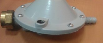
Operating principle of the gas reducer
Based on the type of design, devices are divided into two main types - direct and reverse. Without delving into the intricacies of the design, we can say that the operation of the gas reducer is aimed at reducing the output pressure to the required value using a system of membranes, springs and valves. For compressed gases, reducers are designed for an input pressure of up to 250 atmospheres, for liquefied gases - up to 25 atmospheres. At the outlet, balloon reducers regulate pressure in the range of 1-25 atmospheres. Control of inlet and outlet pressure is carried out using independent built-in pressure gauges (1 or 2).
Bevel gear calculation
The main parameter of the bevel gearbox is the actual range of gear ratios, which is 6.3 (in other versions it can be in the range from 1 to 1000). The main area of application is the transmission of torque between shaft mechanisms. The disadvantage of bevel gearboxes is the relative complexity of their production and installation operations.
When manufacturing a bevel gearbox, the transmission is calculated based on contact stresses, during this process the bending stress is checked, and the volumetric size and weight of the gear wheel devices, the dimensions of the equipment housing base and the integral weight of the bevel gearbox are determined. All of the above parameters are significantly influenced by the choice of type of heat treatment.
Compared to similar mechanisms, the following advantages of a bevel gearbox can be distinguished:
— increased safety during operation; — high axial and radial load-bearing capacity; — a slight increase in output torque; - quiet operation; - long service life and comparative ease of repair and maintenance.
The disadvantages include the complex production and installation technology of the bevel gearbox, as well as large axial and bending loads on the shaft mechanism.
Advantages and disadvantages
The design of bevel gearboxes is similar to cylindrical gearboxes, so their advantages and disadvantages are similar. The main advantage of a bevel gearbox is the arrangement of gears or couplings at an angle. This makes it possible to transmit rotation from the drive shaft to the driven shaft, located at an angle of 90 degrees to the first.
Another important advantage of such a device is its immunity to variable and short-term loads. For this reason, they are often used in production processes with frequent starts.
As mentioned above, bevel gearboxes have a structure similar to cylindrical gearboxes, but they have their own disadvantages. These include:
- lower efficiency;
- Wheel seizures occur more frequently.
Despite the fact that the efficiency of such a unit is 10% lower and cases of gear jamming are possible, bevel gearboxes are in great demand and have found application in many areas.
Bevel gearbox: application and selection.
In bevel-helical gearboxes, the bevel stage is the first stage after the electric motor.
Industrial bevel-helical gearboxes (for brevity we will call them bevel gearboxes) are used in cases where extremely high transmitted torques and severe operating conditions are involved.
For example, they are often found in drives of main conveyors or other industrial equipment.
Euronorm has the ability to complete bevel gearboxes with a motor on the frame, a hydraulic coupling, an external brake, etc., for example, below is an example of a mounted gearbox with a torque arm (rod) for securing against rotation, which we made for one of the customers, with the connection of the electric motor through an adapter flange ( lantern) is a compact and simple solution that does not require alignment of the shafts of the electric motor and gearbox, which greatly simplifies installation and guarantees the correct assembly of the bevel gearbox with the engine by low-skilled personnel.
In addition to the generally accepted configuration of a bevel gearbox with the axes of all shafts located in the same plane, there is also sometimes a need for a more complex configuration of a bevel gearbox, for example, below is another Euronorm project, made to order:
A fan is often placed on the input shaft of a bevel gear in order to more effectively cool the gearbox, since, despite the fact that the efficiency of bevel gears and bevel-helical gearboxes in general is quite high, their surface area is not enough to dissipate even those 2-5 % (depending on the number of stages) of energy that is converted into heat.
In contrast to geared motors, the requirements for bevel gearboxes for heavy industry are somewhat different:
Maintainability - to be able to repair heavy industrial bevel gearboxes, the gearbox housing must have a connector along the shaft axes, and in general does not require special tools and devices. Euronorm bevel gearboxes have all these properties.
Durability and reliability – when purchasing expensive equipment, customers must be confident in a reliable investment.
At Euronorm, gears are produced to precision class 6, bearings and seals are only of the highest quality, from reputable manufacturers: Simrit and SKF are well-known brands to guarantee the quality of the entire product.
The service life and reliability of operation are also influenced by the correct choice of gearboxes.
As a rule, when selecting an industrial bevel gearbox, we focus on a resource of at least 100,000 hours, unless there are other instructions from the customer.
Application of bevel gearboxes
- Equipment of group A is characterized by uniform operation, low inertial masses and the absence of shocks and vibrations.
Includes: filling machines, drilling machines, elevators, packaging machines, screw conveyors, belt conveyors, elevators, fans, mixers, roller shutters, knitting machines, assembly lines, washing machines, manipulators.
- Equipment of group B is characterized by uneven operation, medium-sized inertial masses and an average level of shock and vibration.
Includes: bending machines, batchers, lathes, turntable drives, elevators (heavy), winders, mixers, canning machines, ball mills, flour and feed mills, mixers (heavy), mixers (heavy), sliding gates, packaging machines, weaving machines, winches, concrete mixing machines.
- Group C equipment is characterized by extremely uneven operation, large inertial masses and strong shock and alternating loads.
Includes: balers, sheet metal cutting machines, crushers, briquetting presses, eccentric presses, calenders, piston pumps, paper cutting machines, tumbling drums, agitators, roller conveyors, vibrating machines, rollers, cement mills, centrifuges, shredders.
1.2.2 Worm globoid gearbox
The screw of a globoid worm gear has a convex shape (in other worm gears it is cylindrical). This design feature increases torque transmission and drive power.
Globoid gearboxes are designed for use in environments that require high reliability, absence of backslip and dynamic shocks on the output shaft. Most often, gearboxes of this type are used in drum drives of elevators: the globoid pair is adapted to variable loads arising during lifting and braking of the car, and is able to maintain normal reversibility during operation.
Table 2. Permissible loads for globoid worm gearboxes type ChG
| Standard sizes | Nominal gear ratio | Worm rotation speed, rpm | |||||
| 750 | 1000 | 1500 | |||||
| Rvx, kW | Tout, N m | Rvx, kW | Tout, N m | Rvx, kW | Tout, Nm | ||
| Chg-63 | 10 | 1,2 | 120 | 1,5 | – | 1,9 | 110 |
| 12,5 | 1,1 | 130 | 1,3 | 130 | 1,7 | 110 | |
| 16 | 1,0 | 150 | 1,2 | 150 | 1,5 | 130 | |
| 20 | 0,8 | 150 | 0,9 | 150 | 1,3 | 130 | |
| 25 | 0,5 | 125 | 0,6 | 110 | 0,8 | 110 | |
| 31,5 | 0,4 | 110 | 0,5 | 110 | 0,6 | 90 | |
| 40 | 0,3 | 110 | 0,3 | 100 | 0,5 | 90 | |
| 50 | 0,2 | 100 | 0,3 | 100 | 0,3 | 90 | |
| 63 | 0,1 | 90 | 0,2 | 90 | 0,3 | 80 | |
| Chg-80 | 10 | 2,4 | 250 | 2,8 | 220 | 3,1 | 170 |
| 12,5 | 2,0 | 260 | 2,4 | 240 | 2,6 | 180 | |
| 16 | 1,6 | 260 | 1,9 | 240 | 2,1 | 180 | |
| 20 | 1,5 | 300 | 1,7 | 260 | 1,8 | 200 | |
| 25 | 1,0 | 250 | 1,1 | 220 | 1,5 | 190 | |
| 31,5 | 0,7 | 220 | 0,8 | 200 | 1,1 | 180 | |
| 40 | 0,6 | 220 | 0,7 | 200 | 0,9 | 180 | |
| 50 | 0,5 | 210 | 0,5 | 180 | 0,6 | 160 | |
| 63 | 0,3 | 200 | 0,4 | 170 | 0,5 | 150 | |
| Chg-100 | 10 | 4,3 | 460 | 4,7 | 380 | 6,3 | 350 |
| 12,5 | 3,8 | 500 | 4,0 | 400 | 5,5 | 380 | |
| 16 | 3,0 | 500 | 3,6 | 450 | 4,6 | 400 | |
| 20 | 2,7 | 550 | 3,2 | 500 | 3,9 | 420 | |
| 25 | 2,0 | 500 | 2,3 | 450 | 3,0 | 400 | |
| 31,5 | 1,4 | 420 | 1,6 | 380 | 2,1 | 350 | |
| 40 | 1,2 | 420 | 1,3 | 380 | 1,8 | 350 | |
| 50 | 0,9 | 400 | 1,0 | 350 | 1,3 | 320 | |
| 63 | 0,7 | 380 | 0,8 | 320 | 1,1 | 300 | |
| Chg-125 | 10 | 8,4 | 900 | 10,4 | 850 | 12,3 | 700 |
| 12,5 | 7,1 | 950 | 8,9 | 900 | 10,0 | 700 | |
| 16 | 5,6 | 950 | 7,0 | 900 | 8,5 | 750 | |
| 20 | 5,3 | 1100 | 6,3 | 1000 | 7,8 | 850 | |
| 25 | 4,0 | 1000 | 4,6 | 900 | 5,2 | 700 | |
| 31,5 | 2,9 | 900 | 3,4 | 800 | 3,9 | 650 | |
| 40 | 2,4 | 900 | 2,8 | 800 | 3,2 | 650 | |
| 50 | 1,7 | 800 | 2,1 | 750 | 2,6 | 650 | |
| 63 | 1,4 | 750 | 1,7 | 700 | 2,1 | 600 | |
| Chg-160 | 10 | 16,7 | 1850 | 20,3 | 1700 | 28,3 | 1600 |
| 12,5 | 13,9 | 1900 | 16,3 | 1700 | 22,8 | 1600 | |
| 16 | 11,0 | 1900 | 13,7 | 1800 | 18,6 | 1650 | |
| 20 | 9,7 | 2050 | 11,9 | 1900 | 16,5 | 1800 | |
| 25 | 7,6 | 1950 | 8,6 | 1700 | 11,2 | 1500 | |
| 31,5 | 5,7 | 1800 | 6,4 | 1550 | 8,2 | 1350 | |
| 40 | 4,6 | 1800 | 5,1 | 1550 | 6,6 | 1350 | |
| 50 | 3,6 | 1650 | 4,0 | 1450 | 5,0 | 1250 | |
| 63 | 2,8 | 1550 | 3,4 | 1450 | 4,1 | 1200 |
Classification of gearboxes
Reducer for general machine-building purposes. This type of equipment is an independent unit used in machine drives. Its technical characteristics meet common requirements for different applications. Structurally, general machine-building gearboxes may differ.
Special gearboxes are designed for automotive, aviation and other highly specialized industries. From the name it is clear that the units of this group must correspond to the specifics and parameters of a particular application.
Gearboxes can be classified according to the following criteria:
- By type of gear and number of stages;
- According to the location of the axes of the input/output shafts in space and relative to each other;
- According to the method of fastening.
1.1 Number of stages and shaft arrangement
Two- and three-stage gearboxes of deployed and bifurcated circuits (in the case of two-stage models, also coaxial circuits) have a number of advantages over units of other types - first of all, high efficiency and load resistance. Coaxial helical gearboxes can be equipped with a low-speed stage with internal gearing. Planetary and wave units with coaxial shaft axes also provide high performance and a wide range of gear ratios.
When assembling machines and mechanisms that require an intersecting arrangement of shafts, two- and three-stage bevel (bevel-helical) gearboxes will be effective.
Units with worm (worm-cylindrical, cylindrical-worm) gears are characterized by a high gear ratio and low noise level. However, the efficiency of such models is lower than that of their cylindrical counterparts.
Vertical output shafts require less space. In mechanisms where such an arrangement is necessary, worm or bevel gearboxes are more often used. Convenience lies in the fact that the engine axis is in a horizontal position.
Table 1. Classification of gearboxes according to the location of the shaft axes
| Gearbox | Axes location |
| Parallel axes of input/output shafts | 1. Horizontal:
2. Vertical |
| Coinciding axes of input/output shafts (coaxial) | 1. Horizontal 2. Vertical |
| Intersecting axes of input/output shafts | 1. Horizontal 2. Horizontal axis of input shaft and vertical axis of output shaft 3. Vertical axis of input shaft and horizontal axis of output shaft |
| Crossing axes of input/output shafts | 1. Horizontal (input shaft above or below output shaft) 2. Horizontal axis of input shaft and vertical axis of output shaft 3. Vertical axis of input shaft and horizontal axis of output shaft |
1.2 Types of gears used
1.2.1 Worm gearboxes
Worm gearboxes are the most common type of gearboxes. The drive has compact dimensions (compared to cylindrical units). The gear ratio of the worm pair can reach 1-100 (sometimes higher).
The potential for increasing torque when reducing shaft speed is higher for worm gearboxes than for equipment with other types of gears. A gear ratio of the same order can be obtained when operating a three-stage helical gearbox. In worm units, one stage is sufficient to solve this problem. Another advantage is the simplicity and low cost of worm gearboxes. The use of a worm gear reduces the noise level of the transmission and ensures high smoothness.
The self-braking function is present only in worm gearboxes. Its principle is based on braking the driven shaft in the absence of movement on the drive shaft (worm). Self-braking in the transmission occurs at the moment when the lift angle of the drive shaft is less than or equal to 3.5 degrees.
When choosing a worm gearbox, you should take into account the fact that as the gear ratio increases, the efficiency of the worm gear decreases. Hence the energy loss due to friction of the worm on the teeth of the wheel.
The service life of worm drives is, on average, 10 thousand hours.
1.2.2 Worm globoid gearbox
The screw of a globoid worm gear has a convex shape (in other worm gears it is cylindrical). This design feature increases torque transmission and drive power.
Globoid gearboxes are designed for use in environments that require high reliability, absence of backslip and dynamic shocks on the output shaft. Most often, gearboxes of this type are used in drum drives of elevators: the globoid pair is adapted to variable loads arising during lifting and braking of the car, and is able to maintain normal reversibility during operation.
Table 2. Permissible loads for globoid worm gearboxes type ChG
| Standard sizes | Nominal gear ratio | Worm rotation speed, rpm | |||||
| 750 | 1000 | 1500 | |||||
| Rvx, kW | Tout, N m | Rvx, kW | Tout, N m | Rvx, kW | Tout, Nm | ||
| Chg-63 | 10 | 1,2 | 120 | 1,5 | — | 1,9 | 110 |
| 12,5 | 1,1 | 130 | 1,3 | 130 | 1,7 | 110 | |
| 16 | 1,0 | 150 | 1,2 | 150 | 1,5 | 130 | |
| 20 | 0,8 | 150 | 0,9 | 150 | 1,3 | 130 | |
| 25 | 0,5 | 125 | 0,6 | 110 | 0,8 | 110 | |
| 31,5 | 0,4 | 110 | 0,5 | 110 | 0,6 | 90 | |
| 40 | 0,3 | 110 | 0,3 | 100 | 0,5 | 90 | |
| 50 | 0,2 | 100 | 0,3 | 100 | 0,3 | 90 | |
| 63 | 0,1 | 90 | 0,2 | 90 | 0,3 | 80 | |
| Chg-80 | 10 | 2,4 | 250 | 2,8 | 220 | 3,1 | 170 |
| 12,5 | 2,0 | 260 | 2,4 | 240 | 2,6 | 180 | |
| 16 | 1,6 | 260 | 1,9 | 240 | 2,1 | 180 | |
| 20 | 1,5 | 300 | 1,7 | 260 | 1,8 | 200 | |
| 25 | 1,0 | 250 | 1,1 | 220 | 1,5 | 190 | |
| 31,5 | 0,7 | 220 | 0,8 | 200 | 1,1 | 180 | |
| 40 | 0,6 | 220 | 0,7 | 200 | 0,9 | 180 | |
| 50 | 0,5 | 210 | 0,5 | 180 | 0,6 | 160 | |
| 63 | 0,3 | 200 | 0,4 | 170 | 0,5 | 150 | |
| Chg-100 | 10 | 4,3 | 460 | 4,7 | 380 | 6,3 | 350 |
| 12,5 | 3,8 | 500 | 4,0 | 400 | 5,5 | 380 | |
| 16 | 3,0 | 500 | 3,6 | 450 | 4,6 | 400 | |
| 20 | 2,7 | 550 | 3,2 | 500 | 3,9 | 420 | |
| 25 | 2,0 | 500 | 2,3 | 450 | 3,0 | 400 | |
| 31,5 | 1,4 | 420 | 1,6 | 380 | 2,1 | 350 | |
| 40 | 1,2 | 420 | 1,3 | 380 | 1,8 | 350 | |
| 50 | 0,9 | 400 | 1,0 | 350 | 1,3 | 320 | |
| 63 | 0,7 | 380 | 0,8 | 320 | 1,1 | 300 | |
| Chg-125 | 10 | 8,4 | 900 | 10,4 | 850 | 12,3 | 700 |
| 12,5 | 7,1 | 950 | 8,9 | 900 | 10,0 | 700 | |
| 16 | 5,6 | 950 | 7,0 | 900 | 8,5 | 750 | |
| 20 | 5,3 | 1100 | 6,3 | 1000 | 7,8 | 850 | |
| 25 | 4,0 | 1000 | 4,6 | 900 | 5,2 | 700 | |
| 31,5 | 2,9 | 900 | 3,4 | 800 | 3,9 | 650 | |
| 40 | 2,4 | 900 | 2,8 | 800 | 3,2 | 650 | |
| 50 | 1,7 | 800 | 2,1 | 750 | 2,6 | 650 | |
| 63 | 1,4 | 750 | 1,7 | 700 | 2,1 | 600 | |
| Chg-160 | 10 | 16,7 | 1850 | 20,3 | 1700 | 28,3 | 1600 |
| 12,5 | 13,9 | 1900 | 16,3 | 1700 | 22,8 | 1600 | |
| 16 | 11,0 | 1900 | 13,7 | 1800 | 18,6 | 1650 | |
| 20 | 9,7 | 2050 | 11,9 | 1900 | 16,5 | 1800 | |
| 25 | 7,6 | 1950 | 8,6 | 1700 | 11,2 | 1500 | |
| 31,5 | 5,7 | 1800 | 6,4 | 1550 | 8,2 | 1350 | |
| 40 | 4,6 | 1800 | 5,1 | 1550 | 6,6 | 1350 | |
| 50 | 3,6 | 1650 | 4,0 | 1450 | 5,0 | 1250 | |
| 63 | 2,8 | 1550 | 3,4 | 1450 | 4,1 | 1200 | |
1.2.3 Helical gearboxes
Spur gears are equipped with spur gears. The configuration of such drives may differ in the position of the input/output shafts and the number of stages. Single-stage cylindrical units are classified only by the location of the shafts. Gear ratios vary in the range of 1.6-6.3.
Schemes of execution of cylindrical pairs:
- unfolded narrow;
- expanded;
- forked;
- coaxial
The most common is the expanded scheme. It allows us to produce unified wheels, shafts and gears that are suitable for the production of gearboxes of different sizes. This factor is decisive for mass production, because helps reduce the cost of products.
For the same purpose, the left gear tooth direction and the right wheel direction are selected for all gear stages. When individually configuring a single gearbox, it is more advisable to use the following scheme: left direction of the gear tooth in the first stage, right direction in the second stage. This configuration will reduce the axial load on the supports.
The shape of gearboxes designed according to an expanded scheme is elongated. The weight of such a unit will be 15-20% more than drives designed using a bifurcated design.
The bifurcated scheme is applicable for low-speed and high-speed stages. In the second option, it is the most rational, since the intermediate shaft can be made according to the principle of a gear shaft, and the high-speed shaft becomes “floating”.
In a coaxial design, the axes of the high-speed and low-speed shafts coincide. The weight and dimensions of the gearbox assembled according to a coaxial design are similar to models with an expanded design. The cost of both types of units is almost the same.
One of the main technical characteristics of a coaxial gearbox is increased power of the high-speed stage, which is achieved by reducing the load on it. However, such units are structurally more complex.
The service life of the helical gearbox is 25 thousand hours or more.
Table 3. Permissible loads for CU helical gearboxes (single-stage horizontal)
| Standard sizes | Rated torque on the output shaft, Nm | Nominal radial force, N | |
| input shaft | output shaft | ||
| TsU-100 | 250 | 500 | 2000 |
| TsU-160 | 1000 | 1000 | 4000 |
| TsU-200 | 2000 | 2000 | 5600 |
| TsU-250 | 4000 | 3000 | 8000 |
Table 4. Technical parameters of helical gearboxes Ts2S (two-stage coaxial)
| Standard sizes | Nominal gear ratios | Rated torque on the output shaft, Nm | Nominal radial force, N | Efficiency | |
| input shaft | output shaft | ||||
| Ts2S-63 | 8; 10; 12,5 | 125 | 500 | 2800 | 0,98 |
1.2.4 Bevel gearboxes
The design of the bevel gear provides wheels with straight and circular teeth. The directions of inclination of the tooth line and rotation of the wheel must coincide. Compliance with this condition prevents the gear from being pulled into mesh, which occurs under the influence of a negative axial force on the gear.
The gear ratio of the bevel gear is 1-5.
The gear wheel is installed between the gearbox supports. The gears are mounted cantilever.
1.2.5 Helical-bevel gearboxes
This type of mechanism is a hybrid of a single-stage cylindrical and bevel gearbox. Accordingly, this group of equipment has all the advantages and disadvantages of both types of units.
All bevel-helical gearboxes have a high-speed bevel stage. This design feature is explained by the low load capacity and, accordingly, the large dimensions of the unit. In order to reduce the size of the drive, a high-speed conical stage is used.
Bevel gears can be used in low-speed and intermediate stages, which is justified by the need to reduce its sensitivity to errors during production and installation, minimizing their impact on the mechanism as a whole.
The direction of the tooth in a helical cylindrical pair must be chosen taking into account the possibility of subtracting axial forces on the intermediate shafts.
Table 5. Operating mode coefficient of bevel-helical gearboxes (two-stage and three-stage)
| Character of the load mode | Daily duration of operation | ||
| 3 hours | 8 ocloc'k | 24 hours | |
| Calm | 1,25 | 1,0 | 0,8 |
| Moderate tremors | 1,0 | 0,8 | 0,65 |
| Strong tremors | 0,55 | 0,65 | 0,5 |
1.2.6 Shaft-mounted gearboxes
Mounted gearboxes are units with a hollow output shaft. They are mounted directly on the shaft - without additional connections or gears. The advantage of mounted gearboxes is their more compact dimensions and relatively low weight.
The mounting method is usually applicable to worm gearboxes and some other types of gearboxes. The exception is a cylindrical coaxial group of equipment, the design features of which make such installation difficult.
When the load on the output shaft suddenly changes (most often in emergency situations), the absence of a coupling can cause premature failure of the drive equipment. Therefore, the operation of the gearbox requires the creation of operating conditions with a uniform load. As an option - additional drive protection.
1.2.7 Planetary gearboxes
Planetary (differential) gearboxes consist of a central gear (sun gear) located in the center of the gearbox, auxiliary gears of the same size (satellites) installed around the central gear, and a retainer (carriage) that ensures their secure fastening. The design of the planetary gearbox also includes a ring gear that looks like a gear wheel. Its purpose is to provide traction with the satellites. The central gear is the driving element, the satellites are the driven elements. The ring gear is always stationary.
The design of planetary gearboxes may differ. Models are classified by the number of stages (one-, two- and three-stage), and the kinematic scheme of the planetary gear. The type of bearings is also different. Rolling bearings are designed for low speed operating conditions. In turn, plain bearings are designed for high speed conditions. The main area of use of planetary gearboxes is mechanical engineering.
MPO planetary units are classified as universal drive equipment. They are widely used in drives of mixing mechanisms in the medical, chemical, microbiological industries, as well as in drives for general industrial purposes. Gearboxes of the MPO series can be operated 24 hours a day under constant and variable loads.
Strict requirements are imposed on planetary gearboxes. The production of such equipment requires high precision so that the teeth are in close contact with each other, but are easily set in motion.
Table 6. Technical parameters of Pz planetary gearboxes (single-stage gearboxes)
| Standard size | Carrier radius, mm | Gear ratios | Torque on the output shaft, Nm | Cantilever force, N | Efficiency | Input shaft speed | ||
| input shaft | output shaft | maximum | minimum | |||||
| Pz-31.5 | 32,35 | 8, 10 | 125 | 80 | 140 | 0,96 | 3000 | 500 |
| Pz-40 | 40 | 6,3 | 250 | 120 | 200 | 0,98 | 3000 | 500 |
| 8, 10, 12,5 | 0,97 | |||||||
| Pz-50 | 50 | 6,3 | 500 | 170 | 280 | 0,98 | 3000 | 500 |
| 8, 10, 12,5 | 0,97 | |||||||
| Pz-63 | 63 | 6,3 | 1000 | 240 | 400 | 0,98 | 3000 | 500 |
| 8, 10, 12,5 | 0,97 | |||||||
| Pz-80 | 80 | 6,3, 8, 10, 12,5 | 2000 | 340 | 560 | 0,97 | 1500 | 500 |
| Pz-100 | 100 | 6,3, 8, 10, 12,5 | 4000 | 480 | 800 | 0,97 | 1500 | 500 |
| Pz-125 | 125 | 6,3, 8, 10, 12,5 | 8000 | 680 | 1130 | 0,97 | 1500 | 500 |
| Pz-160 | 160 | 6,3 | 16000 | 960 | 1600 | 0,97 | 1000 | 500 |
| 8, 10, 12,5 | 1500 | |||||||
| Pz-200 | 200 | 6,3, 8, 10, 12,5 | 31500 | 1340 | 2240 | 0,97 | 1000 | 500 |
1.3 Methods of fastening gearboxes
Foot mounts are often used with light alloy bodies to make the unit design as light as possible. The housing has special zones for quickly attaching the gearbox to the base.
When using flange mountings, the gearbox is installed using a flange located on the housing. The output shaft passes through this flange.
The attachment connects the gearbox to the operating mechanism via a hollow output shaft. This shaft is mounted on the end of the shaft of the working mechanism.
Table 7. Classification of gearboxes by mounting method
| Mounting method | Example | Mounting method | Example |
Attachments or plate (ceiling or wall):
| Flanged on the input shaft side | ||
| Flanged on the output shaft side | |||
| Flanged on the input/output shaft side | ||
| Nasadnoe |
Cylindrical units
The most common options. They serve in all areas of industrial production; the advantage of this type is its simplicity, and the absence of the need for cooling, since there is nothing to heat up there.
This class also has a very high efficiency - up to 98%! A certain AK-47 in the world of machine structures.
The ability to withstand heavy loads removes restrictions in the areas of their use. They are used both in metal-cutting machines and in mixers and grinders.
Design features of a helical gearbox
The design of the spur gearbox uses a gear drive. Based on their design, these devices are divided into single-stage, two-stage, three-stage and four-stage models.
The arrangement of the shafts divides helical gearboxes into 2 types:
- design of a helical gearbox with parallel shafts;
- coaxially located shafts (when the distance between the axles is below the interaxle distance of the gears - all single-stage models belong to this class).
Helical gearboxes are mounted in one of 3 ways - on feet, flanges or by the push-on method.
The advantages of the equipment include higher efficiency than that of a worm gear, excellent load capacity and long service life under various operating conditions (including frequent starts and stops). Here you will also find reliability, no self-braking option and a small amount of heat generated. Helical gearboxes allow operation in a wide range of gear ratios, which determines their wide scope of application. All kinds of machines, lifts, mixers, extruders, etc. are equipped with such devices. A feature of cylindrical gears is noise during operation and demanding maintenance.
Wave transmissions
The emergence and further development of wave transmission took place back in 1959. The inventor, as well as the person who patented this technology, was the American engineer Masser.
The wave gearbox consists of several main elements:
- A fixed wheel with internal teeth.
- A rotating wheel with external teeth.
- Driven.
Among the advantages that can be identified from this method of transmitting motion are lower weight and size of the device, higher accuracy from a kinematic point of view, as well as less backlash. If necessary, this type of motion transmission can be used in a sealed space without using sealing seals. This indicator is most important for such equipment as aviation, space, and underwater. In addition, the wave gearbox is also used in some machines used in the chemical industry.
Examples of our helical gearboxes
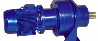
Bevel gearbox, single-stage, air-cooled
Documentation:
Technical and service documentation, test report (without load), manufacturer's confirming certificates will be provided to you free of charge.
Quality certificates:
There are quality certificates and type approvals for the products of the following organizations and societies: GL / DNV / ABS / RS / CCS / LRS / GOST R
Painting and preservation:
Factory standard paint. Preservation of external exposed parts and gear elements with Tectyl 506. Internal components with Tectyl 511.
Our company offers to buy bevel gearboxes from a reliable manufacturer.
- Bevel gearbox
- Kegelradgetrieben
- Reductores de engranajes conicos
Please send your requests for equipment to the technical department of our company by e-mail, tel. +7 (495) 225 57 86.
Central website of the company ENCE GmbH Our service company Intech GmbH
Head Offices in the CIS countries:
Russia Kazakhstan Ukraine Turkmenistan Uzbekistan Latvia Lithuania
Design No. 2
bevel gearbox with horizontal high-speed and vertical low-speed shafts . A special feature of the gearbox design is the lubrication and bearing protection system. The gear is lubricated by dipping the gear in oil. The drive shaft bearings are lubricated separately and each bearing has a double-sided oil-retaining device. The lower bearing assembly is protected from liquid oil getting into it by two cups, fixedly fixed: one on the housing, and the other on the wheel. The glass, mounted on the wheel, has the shape of a cone expanding at the bottom, which ensures that the oil is thrown away from the shaft during rotation.
Design features of the gearbox
The design is a housing that contains all the transmission elements - shafts, gears and bearings, gears and others. Due to the difference in gear ratios of mating gears, the gearbox can reduce the speed of rotation of the output shaft relative to the speed of the input. Thanks to this property, the gearbox is actively used as a drive for various engines and mechanisms. The versatility of use that the gearbox has predetermines its widespread use in industry.
To operate, for example, a conveyor, you need bearings and drive chains that can ensure the movement of various conveyors and loading platforms. All conveyor mechanisms are driven by a gearmotor, which is an electric motor structurally combined with the central gear of a gearbox of any type of transmission.
Due to the fact that the gear motor has a simple design, it does not require constant maintenance, and its compact dimensions allow it to be mounted on the frame of a lifting mechanism without taking up extra space. High-precision positioning gearboxes use radial-axial bearings mounted in composite positions to ensure smooth and silent shaft rotation. Gearboxes of different types are designed differently; their shafts can be located either in the same plane or at an angle to each other. The performance of the gearbox and its gear ratio depend on this.
High-speed shaft versions for bevel gearboxes.
Designs of the high-speed shaft of a bevel gearbox for the case of application between an electric motor and a belt or chain drive gearbox are shown in Fig. 1…4.
Rice. 1, 3, 4 - the gear shaft and pulley (sprocket) bearings are separate. The pulley (star) rests on the glass through its two bearings. The shaft is unloaded from the belt tension forces, the torque from the pulley (sprocket) is transmitted either through an elastic coupling and splines (Fig. 3), or through a rigid compensating clutch (Fig. 1), or through splines (Fig. 4).
Rice. 2 - the pulley is located directly on the shaft and loads it with forces from the belt tension.
Related Pages
- Kinematic diagrams of gearboxes
- Gearbox with vertical shafts
- Gearbox with two high-speed shafts.
- Two-stage gearbox
- Two-stage coaxial gearbox
- Design options for shaft supports of a cylindrical two-stage coaxial gearbox
- Gearbox with torsion shafts
- Two-stage, three-flow coaxial gearbox
- Coaxial cylindrical gearbox with internal gearing of low-speed stage
- Geared motor MTs2S-125
- Cylindrical gearbox Ts2-160
- Two-stage cylindrical gearbox 1Ts2U.
- Gearbox Ts2-200.
- Special gearbox
- Gearbox Ts3KF-100
- Reducer RTC-500.
- Three-stage gearbox
- Reducer RCT-1015.
- Bevel gearbox K-125.
- Bevel-helical gearbox
- Worm gearbox.
- Helical worm gear motor.
- Helical-worm gearbox.
- Two-stage worm gearbox.
What does a gearbox do?
The word reducer itself literally means reduction. Accordingly, editors were invented in order to reduce the rotation speed. At the same time, the gearbox increases the torque power. As we already said at the beginning of the article, gearboxes are used in cars. There they are needed in order to carry out downshifts and returns. This principle can be clearly seen in the example of the operation of bicycle gears, where the role of a gearbox is performed by the so-called sprockets. Note that today gearboxes are used not only in cars, but also in many engines, as well as to reduce and maintain the pressure of the working environment, including gas, steam and liquid.
Gears and bevel gear parameters
The type of gearbox depends on the composition of the gears and the position of the axes of rotation of the shafts. There are the following types of gears: cylindrical, planetary, bevel, worm, globoid and wave. One of the types of angular gearbox is a bevel gearbox, which serves to reduce the rotation speed while simultaneously increasing the torque. The mechanism housing contains gears with a constant gear ratio.
The bevel gearbox has the following parameters: low peripheral speed, average level of reliability, accuracy and metal consumption, relatively low cost and labor intensity. In addition, depending on the type of gears, the location of the axes of the shaft mechanism and the number of stages, bevel gearboxes are divided into coaxial mechanisms, parallel devices, crossing and intersecting devices, they can have a horizontal or vertical arrangement of the axes of the shaft mechanism and are mounted either on a slab base or on attached support legs. Also, the axis of the output shaft mechanism can be located on the side, above or below, relative to the plane of the base.
A modern bevel gearbox has a wheel connection with circular teeth. To avoid negative axial force on the gear, it is necessary to ensure that the direction of rotation of the gear wheel connection coincides with the inclination of the tooth line. The range of gear ratios is from 1 to 5, the most common angle of inclination is 350. There are also bevel-helical gearboxes, which are made with a high-speed bevel stage.
Input and output shafts of gearboxes
Gearboxes usually use conventional straight shafts in the shape of rotating bodies. The gearbox shafts are subject to external loads, cantilever loads and forces to overcome gears. The torque on the shaft is determined by the operating torque of the gearbox or the reactive torque of the drive. The cantilever load is determined by the way the gearbox is connected to the engine and depends on the radial or axial force on the shaft. In a number of machines that have special requirements regarding dimensions or weight, hollow shaft gearboxes are used. The hollow gearbox shaft allows the actuator shaft to be located inside the gearbox, thereby eliminating the need to use adapter coupling halves, etc.
Design of bevel gearboxes
When designing a bevel gearbox, special attention is paid to strong and durable bearing supports. To install bevel gear shafts, tapered roller bearings or deep groove ball bearings are most often used, depending on the design. For special versions, angular contact ball bearings are used to reduce temperatures or reinforced bearings for very high shaft loads. The bearing life is designed for 20,000 operating hours.
When designing bevel gear housings and bearing arrangements, care must be taken to ensure that excessive shaft movement does not occur during operation. It is equally important that the housing and parts to be installed in terms of parallelism, perpendicularity, fit and concentricity are manufactured within specified tolerances.
- Bevel gear hole position tolerance: ±0.02mm
- Permissible axis deviation from an angle of 90°: ± 2 arc minutes
To select the correct bearing design, it is necessary to know the magnitude and direction of the forces in the gearing and any external additional forces. For helical bevel gears, the axial forces resulting from the axial components of the tooth contact must be taken into account for the bearings. The direction of these forces depends on the direction of the helix of the bevel gears and the direction of rotation. In standard bevel gears, the gear is left-handed and the gear is right-handed.
An important parameter of the gearbox is the backlash in the bevel gear. Bevel gears are designed to operate with a preset backlash. The amount of play depends on the engagement module. If the play is set too much or too little, noise and premature wear may occur. A special gearbox with reduced backlash is also available upon customer request.
The noise level during operation of a bevel gearbox is about 75 dB, and depends on the quality of the gear drive. The maximum permissible surface temperature of the gearbox housing is 80°C. The bevel gear shaft seals can be with or without a dust lip, according to DIN 3760. The seal material is NBR or Viton.
Solid shafts are designed with keys according to DIN 6885/1 and center holes according to DIN 332/2. The hollow shafts of the gearbox have a keyway in accordance with DIN 6885. In addition to the standard bevel gearbox configuration, gearboxes with several output shafts, up to a total of 6, can be supplied. A special version of the bevel gearbox is available with stainless steel or chrome plated shafts. Structurally, bevel gearboxes can be equipped with solid or hollow shafts, a flange for mounting the motor or a flange on the output shaft side.
The standard range of available bevel gearboxes is divided into a sufficient number of standard sizes that determine the size of the gearbox and the corresponding indicators of the transmitted torque. Bevel gearboxes also differ in the standard gear ratio from 1 to 6, which affects the speed and power of a particular gearbox. Bevel gearboxes with gear ratios other than standard are available on request. The bevel gear can be used as both a reduction and an increase (up to a maximum of 2) gear transmission.
To correctly select a bevel gearbox, the operating parameters required for the respective drive must be determined according to proper calculations. In particular, different load cases, operating times and environmental conditions must be taken into account. The possibilities of a bevel gear drive are not unlimited, therefore, all operating factors listed in the tables must be observed. Normal operating conditions are the specified power values, constant load during steady operation, low inertial masses and 8 -10 hours of operation per day at an ambient temperature of 20°C.
Gearbox service life
The service life of the gearbox depends on correct calculations of the operating load parameters. Also, timely preventative maintenance of the gearbox, changing oil and seals also affects the duration of operation. Regular preventive inspection will allow you to avoid unplanned repairs or replacement of the gearbox. The oil level is monitored through an inspection window in the gearbox and, if necessary, topped up to the required level.
Below is a table of the dependence of the gearbox service life on the transmission type:
| Gearbox type | Guaranteed resource in hours |
| Cylindrical, planetary, conical, cylindrical-conical | more than 25000 |
| Wave, worm, globoid | more than 10000 |
Sketch layout of the gearbox
The sketch layout establishes the position of the gear and wheel of a closed gear transmission, the gear of an open gear and the coupling relative to the walls of the gearbox housing and bearing supports, determines the distances l
B and
l
Between the points of application of reactions of the bearings of high-speed and low-speed shafts, as well as the points of application of pressure forces from the open gear gear and clutch at a distance
l
op and
l
m from the point of application of the reaction of the near bearing (Fig. 3.2).
If necessary, the sketch layout is carried out in accordance with the requirements of the ESKD on graph paper in A2 or A1 format with a pencil in contour lines on a scale of 1:1 and must contain a sketch image of the gearbox in two projections, the main inscription (see Fig. 3.2 and Fig. 6.1 form 1 ). It is recommended to carry out the sketch layout of the gearbox in the following sequence:
1. Outline the location of the layout projections in accordance with the kinematic drive diagram and the largest wheel sizes.
2. Draw the projection axes and the axial lines of the shafts.
In a cylindrical gearbox, the shaft axes are positioned at an interaxial distance parallel to each other, in a bevel gearbox - at an angle of 90°.
Fig.3.2
3. Draw the gear train in accordance with the geometric parameters of the gear and wheel obtained as a result of the design calculation. The wheel engagement points are shown in accordance with Fig. 3.3: a
– cylindrical gear;
b
– conical.
Fig.3.3
4. To prevent the surfaces of the rotating wheels from touching the internal walls of the housing, the contour of the walls is drawn with a gap = 8…10 mm. Distance hM
hM
is taken between the bottom of the housing and the surface of the tops of the gear teeth for all types of gearboxes (in order to ensure an oil settling zone).
The actual contour of the gearbox housing depends on its kinematic diagram, the dimensions of the gear parts, the method of transportation, lubrication, etc., and is determined when developing the structural layout.
5. Draw the shaft steps on the corresponding axes in accordance with the geometric dimensions d
and
l
obtained in the design calculation of the shafts (see Table 3.1), and by graphically determining the design of the shafts for the spur gearbox (see Fig. 3.1,
a
,
b
and Fig. 3.2).
The shaft steps are drawn in sequence from 3rd to 1st. In this case, the length of the 3rd stage l
3 is obtained structurally as the distance between the opposite walls of the gearbox or equal to the length of the wheel hub.
6. At the 2nd and 4th stages, draw the contours of the bearings according to dimensions d , D , B (T, C)
in accordance with their installation diagram (see Table 3.2). For tapered roller bearings
The contours of the bearings are drawn as main lines.
7. Determine distances l
B and
l
T between the points of application of reactions of the bearings of high-speed and low-speed shafts.
The radial reaction of the bearing is considered to be applied at the point of intersection of the normal to the middle of the contact surface of the outer ring and the rolling body of the bearing with the shaft axis (Fig. 3.4):
a) for a radial bearing, the point of application of the reaction lies in the middle plane of the bearing, and the distance between the reactions of the shaft supports (see Fig. 3.4, c): lТ = LT - B;
b) for angular contact ball bearings and tapered roller bearings, the point of application of the reaction is shifted from the middle plane of the bearing and its position is determined by the distance a
, measured from the wide end of the outer ring (see Fig. 3.4,
a
,
b
):
for angular contact single row ball bearings;
for tapered single row roller bearings.
Here d, D, B, T -
geometric dimensions of bearings;
— contact angle; e
— axial load coefficient.
Fig.3.4
8. Determine the application points of cantilever forces:
a) on the output shaft of force (pressure F
continuous or chain transmission;
gear engagements Ft
op,
Fa
op,
Fr
op) are considered to be applied to the middle of the output end of the shaft
l
1 at a distance
l
op from the point of application of the reaction of the near bearing (see Fig. 3.4
c
).
b) coupling pressure force F
m applied between the coupling halves is considered distributed, so we can assume that the point of application of the force
F
m is located in the middle of the output end of the corresponding shaft at a distance of
l
m from the point of application of the reaction of the adjacent bearing (see Fig. 3.4,
a
and
b
).
9. Mark the required dimensions on the projections of the sketch layout.
An example of the output shaft design is shown in Fig. 3.4, in
. A single-stage helical gearbox usually uses a gear with a symmetrical hub and places it at equal distances from the supports.
In individual and small-scale production, the shafts are made in steps, equipped with collars to support the wheels and bearings. In all design options, the bearings are installed “by surprise”. Adjustment of the output shaft bearings, as well as the input shaft bearings, is carried out by installing a set of thin metal spacers under the flange of the screw cap, and in designs with a recessed cap, by installing a compensating ring when using a radial ball bearing or a pressure screw when using tapered roller bearings.
Gearbox lubrication
In order to prevent premature wear of gearbox components and reduce power losses as a result of friction, lubrication of bearings and gears is used.
In gearboxes of low power and low meshing speed, lubrication is carried out by splashing or using an oil bath. The worm, wheel (geared or worm) and spray ring are partially immersed in the same oil that is poured into the housing.
To lubricate high-power high-speed equipment, oil is supplied to the engagement zone by a pump from an oil bath. For bearings, lubricant of a liquid or thick consistency is used.
Gear housings
The main requirements for the gearbox housing are rigidity and strength, eliminating the possibility of shaft misalignment. In modern gearbox production, two types of housings are produced - split and one-piece.
The split housing design includes a base and a removable cover. Some models of vertical helical gearboxes have connectors along 2-3 planes. To prevent oil leakage, the gear housing connectors are treated with sealant. It is not recommended to install gaskets between the cover and the base, since they are deformed when fixing the mounting bolts. As a result, the bearings may not fit properly.
The one-piece housing is more often used for worm gearboxes and other types of equipment that are lightweight. This design includes a removable lid.
For the production of gearbox housings, mainly cast iron grades SCh 10-15 are used. Sheet steel is used less frequently, as a rule, when completing large-scale drive equipment for individual orders. The welded steel housing has a wall thickness that is approximately one third less than that of cast iron gearboxes. Recently, aluminum alloys have been increasingly used for the production of housings.
Gear ratio
Based on functionality, gearboxes are divided into general-purpose and special-purpose devices. In the first case, the parameters of the equipment when used with different equipment are already specified by GOSTs and standards. In the second, specific requirements can be established, according to the operating mode plan and the conditions of future operation of the drive systems.
Depending on the class of gearbox for its intended purpose, it may have a different range of gear ratios (ratios). The latter largely determine the capabilities of the device and depend on design factors:
- number of steps;
- type of gears used.
In modern devices, the gear ratio can reach up to 100,000. It can be constant or variable and divides all mechanisms according to the number of rotational speeds into one-, two- and multi-speed. The first ones have a constant gear ratio, the second and third ones have a variable gear ratio.