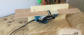
The guide posts are made from axles on rubber rollers, and then a piece of C-profile with a welded place for the engine is attached to them. These axles are driven into a piece of plywood 20 mm thick, having previously drilled the holes 0.5 mm narrower.
The lever for lowering the electric motor is part of some kind of door pin. Well, after all the assembly, powder painting.
The lighting is an assembly of three LEDs cut from 12-volt LED strips powered by a converter in parallel with the motor. A converter for them is also desirable, because the engine is under voltage in the range of 18-24 V. Although you can get by with a regular quenching resistor.
Instead of a motor from a printer, you can use another one with a lower voltage, for example from a cordless screwdriver - whoever has what.
Motor speed controller
To control the rotation speed of the 12-volt DC motor, on which the miniature drilling machine is built, this PWM module was purchased. Its cost on Aliexpress was 108 rubles, excluding delivery costs in the fall of 2022.
Module characteristics:
- Operating voltage: DC6V-DC28V
- Power control: 0.01-80W
- Maximum current: 3A
- Quiescent current: 0.01A (standby)
- PWM duty cycle: 0%-100%
- PWM frequency: 15 kHz
- Board size: 32mm * 50mm * 15mm
During operation, a red SMD LED lights up on the module, which changes the brightness of the light in accordance with the selected power mode.
The module circuit is based on chips and microcircuits:
- LR8726 (IOR) - 30V, HEXFET Power MOSFET.
- S10 45 GKIKG412 (ST) - It is possible that this is a Schottky Barrier Rectifier (current rectifier) 45V 5A.
- NE555 is a universal timer - a chip for generating single and repeating pulses.
A small heatsink was installed on top of the elements with the TO252 housing, but there was no thermal interface in the form of thermal paste. In addition, the surface of the radiator was not smooth enough.
These shortcomings were easily eliminated - the radiator was sanded and KPT-8 thermal paste was applied. However, newer revisions of these modules do not have such a heatsink, and the descriptions on the sellers’ pages indicate that the device can safely operate like this.
December 15, 2022. Additions February 7, 2022.
GTXpert
| Shopping with ALME.RU is an easy way to get an additional discount (cashback) on Aliexpress and other stores. |
Micro drills
A set of 60 pieces of fairly high-quality microdrills from 0.5 to 1 mm, in convenient “capsule cases”, separate for each size, for a symbolic price of 115 rubles (roughly 1.9 rubles per piece) (excluding delivery costs).
The label says HSS Straight Drill, size and quantity, the rest is hieroglyphs.
60 pcs per set, 10 pcs of each size.
Approximate length of each size: 0.5mm drill: 22mm 0.6mm drill: 23.5mm 0.7mm drill: 27.5mm 0.8mm drill: 29.5mm 0.9mm drill: 31.5mm 1.0mm drill: 34mm
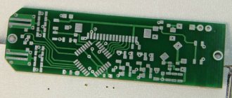
Several drills, 1 mm and 0.7 mm, were successfully tested in the manufacture of an expansion board for the power supply. Drilling was done using a screwdriver, and the drills withstood it. So far there were few holes, but the drills did not have time to become dull. In general, at first glance, they are made of high-quality steel.
Later, a miniature drilling machine was made for drilling.
However, there are some drawbacks: some drills are sharpened off-center, but this can be corrected using a miniature diamond wheel.
.
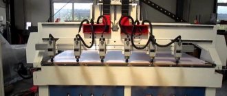
Dual spindle machine
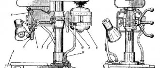
A two-spindle machine is used to bore holes on both sides and turn the ends of parts. But there are several nuances in this equipment that are worth getting acquainted with:
- The OS-402A vertical double-spindle deep drilling machine has a stepped and automatic drilling cycle.
- To increase its own productivity, a double-spindle rotary milling unit has been developed.
- The design of a two-spindle machine for lapping reinforcement was designed and manufactured at the Lenenergo enterprise.
- To screw two threaded parts simultaneously from both ends of the roller, a two-spindle unit with a mechanical drive with a horizontal spindle was manufactured at another production facility.
- The three-spindle unit type C - 13 and the unit type C - 12 are similar in technical characteristics and design. But there is also a difference between the machines, where the table of a two-spindle machine has a shorter length.
- There are rotary table surface grinders with one or two spindles. The difference is that with a dual-spindle machine, one spindle is used for preliminary grinding and the other is used for final grinding.
- Devices for rolling rods and fillets on shafts are in great demand among the population. Only in some cases can one count on the simultaneous rolling of two shafts on their side for a two-spindle machine; the installation of a special valve is also present on the machine.
- The specialized machine has manual control and, thanks to the 4723D model, a mechanical drive. The machine is also used for multi-position processing of many parts. Its kit includes the following: a machine tool, a machine generator of unipolar pulses, a high-frequency electronic semiconductor generator. In contrast to this model, the double-spindle machine is reinforced with an L-shaped traverse.
It is worth noting that each dual-spindle unit represents the most powerful equipment for any workshop, which any master should use.
Do-it-yourself mini electric drill - very simple and fast
And again, good day to all, dear enthusiasts of homemade devices, tools and other mechanisms.
Today I am pleased to share with you a simple method for making a simple, budget-friendly option for making a mini electric drill. Then we will consider with you the identified pros and cons of the resulting product. The mini drill has become widespread and is used to perform an incredibly large number of tasks at home, in the garage, in the country or for repairs. A mini drill is used for a wide variety of small jobs. In particular, it is used for drilling electrical printed circuit boards; a conventional electric drill is completely unsuitable for such work. A mini drill equipped with special attachments can be used as an engraver, a grinder or a router. To use it in this capacity, special nozzles with a rough working surface are used. During operation, the nozzle processes the part or applies the required pattern to the product being processed. Of course, a mini drill will not be able to handle thick iron, but a hole in a metal sheet up to one millimeter thick will be enough to drill. There are an unimaginable variety of options for making a mini-drill with your own hands. Everything fits into your flight of imagination, fantasy and is limited solely by the components available to you for making a drill. So your imagination is limited only by your spare parts bins. The heart of any mini drill is a small but quite powerful electric motor. Also, for the manufacture of our mini drill, you will need a collet chuck (a collet chuck is a type of drill chuck. They hold the drill in the drill during the drilling process. The quality of the work performed by the electric drill depends on the quality of the collet chuck and, accordingly, the fastening of the drill to the electric motor. Therefore, the choice of collet cartridge should be approached with all responsibility), it is quite problematic to make a high-quality collet cartridge on your own at home, so it is better to purchase it in a store. Standard chucks (with collets for drills with a diameter of 0.5 to 3.2 millimeters) can be found in any online store at an affordable price, the price varies from 100 to 150 Russian rubles
An important part of the mini drill, where all the components are placed and attached, is the body. There are many options, in our case we use a pipe from a fan pipe, the inner diameter of which perfectly matches the outer diameter of the electric motor
When fixed in the housing, the engine stood up with virtually no gaps. Connecting electrical wires are selected based on the power of the drill, but due to the fact that we are using an electric motor with low power consumption, we select insulated electrical wires of small cross-section. For high-quality soldering of an electrical circuit, we will need soldering acid and tin rods, a soldering iron or connectors. Almost any novice DIY enthusiast can assemble a mini drill on their own. It's a matter of desire and perseverance. As always, about observing safety precautions when working with high-risk tools. Work carefully. Following all safety regulations. Do not taste electricity with your tongue, do not stick your fingers where the dog does not stick its tail. Before any action, turn on your brain. And then, take my word for it, each member of your friendly family, including the dog, will have their own mini drill.
↑ Study 1
To be honest, it didn’t work out for me - I got beats and vibration. I tried using locking ones instead of screws (without heads) - almost the same result. Most likely, this is due to the mass ratio of the motor and cartridge. Maybe someone will succeed - the motor clearly deserves attention.
Then the ejector drive motor caught my attention. I had a collet chuck from a Soviet drill - you probably remember - a small motor with a thin shaft and a hefty power adapter. So, the chuck from this drill almost matches the diameter of the shaft in its seat. I wound one layer of copper foil onto the shaft - and the cartridge had to be pressed in a vice (being careful). In general, I think a good turner should be able to cope with this task, but I was just lucky.
Let's continue. From the remains of the LED chassis (see Fig. 2, green lines) we make a suitable bracket and install the drilling head on it. We attach the unit with screws to the carriages in place:
So, the bed is ready! Need a base for the machine. Without a base, it’s some kind of drill or something...
PS.
When I was disassembling the SD, the thought flashed through to use its body as a base - this would result in almost complete unification! But! Firstly, the toad crushed it, and secondly (also important) - if you mount the frame directly on the body, you need to drill a hole in the body for the drill to exit. And if there is a hole (even a small one!), then within a week the body will be clogged with shavings. In order not to drill, we would have to install a false table on the body, in which this very hole would be drilled. Then why do we need a building? In short, the toad won. I'll tell you a secret - I stole a cutting board from the kitchen (there's even a hole in it - hang the machine on a nail). A plate made of textolite-getinax with a thickness of about 8-12 mm is probably best suited. Now it’s who has what. Although remounting the machine on a new base - ugh! - Re-tighten 4 screws.
So, we mount the frame on the kitchen base:
Because We will drill not only small boards, but also ensure a gap between the frame and the base. We provide it by installing the frame with screws:
I couldn’t think of anything smarter to ensure clearance than to screw one M4 nut onto the mounting screws. You can use washers - in short, the size of the gap can be adjusted - the main thing is that the board moves freely in this gap. The working field (the distance from the center of the drill to the nearest support) is 80 mm - enough for my purposes (after all, if it doesn’t fit, you can drill the center of the board manually). And this is not a dogma - you can organize the mounting of the machine differently. Or you can actually dismantle the machine from the frame and use it to crawl around the board...
Red arrows indicate the mounting locations of the frame. I also thought about mounting the jibs - they are schematically drawn in blue - but it turned out that it was not necessary. Green - the size of the working field.
You can already drill by removing the upper motor and moving the carriages with your fingers. The head carriages move smoothly. But this very engine haunts me. This is an electric supply with a gearbox! Just install the limit switches and press the pedal button.
Parts for assembly
- Engine with chuck and collet. On the one hand, a jaw chuck is very convenient, but on the other hand, it is much more massive than a collet clamp, that is, it is often subject to beats and very often they have to be additionally balanced.
- Plywood parts. A link to files for laser cutting in dwg format (prepared in NanoCAD) can be downloaded at the end of the article. You just need to find a company that deals with laser cutting of materials and give them the downloaded file. I would like to note separately that the thickness of the plywood may vary from case to case. I come across sheets that are a little thinner than 5mm, so I made the grooves 4.8mm each.
- 3D printed parts. A link to files for printing parts in stl format can also be found at the end of the article
- Polished shafts with a diameter of 8mm and a length of 75mm - 2 pcs. Here is a link to the seller with the lowest price for 1m that I saw
- Linear bearings 8mm LM8UU - 2 pcs.
- Microswitch KMSW-14
- Screw M2x16 - 2 pcs.
- Screw M3x40 h/w – 5 pcs.
- Screw M3x35 slot - 1 pc.
- Screw M3x30 h/w – 8 pcs.
- Screw M3x30 h/w with countersunk head - 1 pc.
- Screw M3x20 h/w - 2 pcs.
- Screw M3x14 h/w - 11pcs
- Screw M4x60 slot - 1 pc.
- Bolt M8x80 - 1 piece
- Nut M2 - 2 pcs.
- M3 square nut – 11pcs
- Nut M3 – 13pcs
- M3 nut with nylon ring - 1 pc.
- Nut M4 - 2 pcs.
- M4 square nut – 1 piece
- M8 nut – 1 piece
- Washer M2 - 4 pcs
- Washer M3 – 10pcs
- M3 washer enlarged - 26 pcs.
- M3 locking washer – 17 pcs.
- M4 washer - 2 pcs.
- M8 washer - 2 pcs.
- M8 locking washer – 1 piece
- Set of installation wires
- Heat shrink tube set
- Clamps 2.5 x 50mm - 6 pcs
DIY drilling machine
What to do if you don’t have a drilling machine for printed circuit boards at home? Of course, it’s expensive to buy, and it happens that the machine is not needed for frequent use.
I offer you 2 simple ideas for making your own drilling machine with your own hands. The first option is very simple; to make it we will need an electric motor from cassette recorders.
Remember these? Such motors can be removed from any Chinese or Soviet-made tape recorder.
They look something like this:
So, we have an electric motor, we also need a drill of the required diameter, usually 0.7-1 mm, we need to take thin paste from a ballpoint pen, a thin thread of 10 centimeters, scissors and instant glue.
Is everything ready? Let's start collecting.
We take the scribbled paste from a ballpoint pen (you can use a new one) and cut off 15 mm, then we need to put it on the motor shaft a little less than half (6-7 mm). Then remove it with a screwdriver or tweezers and put it aside (although you don’t have to remove it).
We take a drill, wind a thread on it turn to turn in 2 layers, below is the photo:
Holding the end of the thread (so as not to unwind), apply a drop of second glue and quickly push the drill into the tube. If you hesitate, the glue will harden.
Here's what we got:
If the drill rotates crookedly, you simply bend the paste in the desired direction until the drill is centered, and you can start drilling your board
Second version of the drilling machine
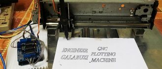
Now I’ll tell you about the second version of the drilling machine, the one I use. Making it will be a little more difficult. I will not give detailed drawings with dimensions, because...
the machine was assembled from what we have, let the article be for informational purposes only, but I will still describe the machine in photographs and schematically.
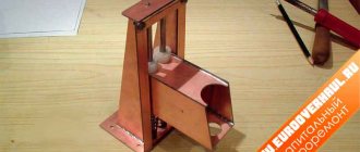
You can try to assemble a similar machine for yourself using my drawings. This machine looks like this:
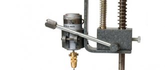
- It is built on a lever mechanism, when pressed, the motor and the drill are lowered, and if the lever is released, the motor rises up again.
- Here is a photo of the mechanism itself:
The lifting and lowering part is made of sheet metal, the sheet is cut to the desired shape, bent and holes are drilled. Instead of the bent rod shown in the photo, you can use something similar, for example, replace it with two long M4 screws with a thread at the end.
- Mechanism drawings:
- Drawing of the lifting mechanism.
- To avoid confusion, I drew the lifting and lever mechanisms separately
- This is what you get if you combine the two top pictures
- I think the essence is clear and now, using my sketches, if you wish, you can put together something similar, I gave you the idea, so go for it!
I also want to give a little advice about drills, drills become dull very quickly and begin to drill poorly, if you don’t have a sharpening machine, then why not throw them away? I found the following way out of this situation: we take a drill and carefully break off the end of the drill with pliers (a millimeter or a little more), and we don’t need to break it off haphazardly, as correctly shown in the pictures below.
↑ Inside the CD drive
The working stroke of this tandem is about 10 mm - quite enough. You can, of course, file something down in order to increase the drill stroke by bringing the carriages closer together, but there is no point - the machine is only intended for drilling circuit boards (at least for me). PS. It was not possible to dismantle one laser - so you can safely write “laser” in the name of the machine!
Now you need to think about the bed. Let's look at the chassis of the same drive:
We cut along the red lines, trim the corners to taste. The cut along the green lines will be useful to us later. Don’t forget to remove burrs - sources of injury. As a result, we get two identical, but symmetrical brackets:
I didn’t check the angles - after all, TEAC
- a decent company. Having drilled the necessary holes, we assemble the frame, focusing on the shelves and corners available on the parts:
View from the back (from inside the machine):
The arrows indicate the places where the parts mate. These shelves and corners make assembly so much easier! Don't forget to install spring washers under the nuts - it's a machine, after all! Vibration…
Now you need to think about the drill head. At first I wanted to adapt my DPR-12-2 27V 5000 rpm
(It was for him that the second carriage was fenced, and, as it turned out, not in vain!). But my motor on this design looked like a bull in a china shop!
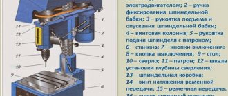
Design
At first glance, the scheme seems complicated, however, it is not. In fact, the mini machine is not very different from the classic one; it is smaller in size with some nuances in the design layout.
Since this equipment is not large in size, it should be considered as desktop equipment. The homemade version of the equipment is usually slightly larger than the purchased one, due to the fact that when assembling it yourself, it is not always possible to optimize the design by selecting small-sized components. But even in this case, the homemade machine will have small dimensions and weight no more than 5 kg.
Assembly video
Elements of a drilling machine
To assemble a mini device with your own hands, you will need the following:
- Bed;
- Transitional stabilizing frame;
- Bar for moving;
- Shock absorber;
- Height adjuster handle;
- Engine mount;
- Engine;
- Collet (or cartridge);
- Adapters.
It is worth noting that we are describing a homemade mini drilling machine, assembled from improvised materials with your own hands. The factory design is distinguished by the use of specialized components that are almost impossible to make with your own hands. The basis of a mini drilling unit, like any other, is the frame. It serves as the base on which all the nodes will be held. The frame can be a handy device, for example: the skeleton of a microscope; stand for linear measurements with a digital indicator.
Or you can make it yourself, for example, a light wooden frame - by connecting the boards with self-tapping screws, or a heavy and stable one - by welding a steel profile to a metal sheet. It is better when the weight of the frame is higher than the main weight of the other components, this increases the stability of the unit and reduces its vibration during operation.
Motors for PCB Drilling Machines
Another interesting scheme based on spare parts from a CD-ROM and a hair dryer with automatic adjustment of the engine speed depending on the load.
Homemade bed
When making a steel frame with your own hands, you can screw the legs under it to fix its position. The stabilizing frame can be made, for example, from a slats or corners, but it is better to use steel. The type of bar for moving can be chosen in any way, the most convenient, and at the same time better combine it with the shock absorber. In some cases, the shock absorber itself may be such a bar. The functions of these parts are to vertically displace the equipment during operation. You can make the shock absorber yourself or remove sliding slats from office furniture, or buy them in a store. The height adjuster handle is installed on the body, stabilizing rail or shock absorber. The motor mount is installed on the stabilizing frame, it could be, for example, a simple wooden block. It is needed to bring the motor to the required distance and securely fix it. Then the motor is installed directly on the mount. A chuck or collets are directly attached to the motor, to which adapters used for installing drills are attached. Adapters are selected individually, depending on the motor shaft, its power, type of drills, etc. In conclusion, we can say that the assembled mini drilling machine can be constantly modified during operation. For example, you can stick an LED strip on the chuck to illuminate the samples being drilled.
↑ Study 2
Having connected 12V to the drilling head, I try to apply voltage to the carriage drive motor using the “poke” method. It doesn't work with haste. If you apply 12V to the carriage drive motor, the board does not have time to drill and the mechanical protections on the carriages begin to click. If the voltage is lower, it is drilled, but not always. The carriage drive motor must have low speeds and at the same time sufficient power. I think by using PWM on the carriage drive motor, you can try to achieve success. We'll put it off for now. Maybe someone will have some ideas.
List of components
Here is a complete list of everything needed for assembly:
- Printed circuit board (link to manufacturing files at the end of the article)
- U1 - MC34063AD, switching regulator, SOIC-8
- U2 - LM358, operational amplifier, SOIC-8
- U3 - L78L09, stabilizer, SOT-89
- D1,D3 - SS14, Schottky diode, SMA - 2 pcs
- D2 - LL4148, rectifier diode, MiniMELF
- C1 - capacitor, 10uF, 50V, 1210
- C2 - capacitor, 3.3nF, 1206
- C3, C4 - capacitor, 4.7 µF, 1206 - 2 pcs
- C5 - capacitor, 22uF, 1206
- R1-R3,R7,R9,R11 - 1 Ohm resistor, 1206 - 6 pcs.
- R4, R10 - resistor 22 kOhm, 1206 - 2 pcs.
- R5 - 1kOhm resistor, 1206
- R6 - resistor 10-27 kOhm, 1206. The resistance depends on the rated voltage of the motor used. 12V - 10kOhm, 24V - 18kOhm, 27V - 22kOhm, 36V - 27kOhm
- R8 - resistor 390 Ohm, 1206
- RV1, RV2 - subscript resistor, 15 kOhm, type 3224W-1-153 - 2 pcs.
- XS1 - terminal, 2 pins, pitch 3.81mm
We also made a limiter ring on a 3D printer for easy installation on the engine. The download link for the STL file is at the end of the article.